Advertisement
Quick Links
Version #2.1
July 16, 2021
Stock Code #
SM812-FJ-Cedar
Thank you for purchasing a
8x12 SpaceMaker. Please take
the time to identify all the parts
prior to assembly.
Safety Points and Other Considerations
Our products are built for use based on
proper installation on level ground and
normal residential use. Please follow the
instruction manual when building your
shed and retain the manual for future
maintenance purposes.
Customers are responsible for ensuring
a solid, level, well-draining site for
construction.
Please check with your local municipal
or county by-laws before ordering this
product to confirm it complies with
building codes.
In the event of a missing or broken piece, call the Outdoor Living Today Customer Support Line @ 1-888-658-1658 with-
in 30 days of the delivery of your purchase. It is our commitment to you to courier replacement parts, free of charge,
within 10 business days of this notification. Replacement parts will not be provided free of charge after the 30 day
grace period.
All structures purchased from Outdoor Living Today are covered for a period of one year for defects in manufacturing
and workmanship. Costs incurred for customer installations are not included.
Failure to use supplied parts included in this kit could result in poor product performance and may void your warranty.
Please contact Outdoor Living Today's Customer Toll Free Line if you plan to deviate from our written instructions.
Toll Free 1-888-658-1658
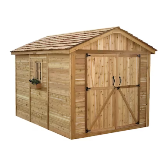
8x12 SpaceMaker Shed
FJ Bevel Model with Cedar Roof
Assembly Manual
- Snow load ratings vary by geographical location. If heavy or wet snowfall occurs, it
is advisable to sweep snow off roof frequently.
- If the product is elevated, any structural and building code requirements are solely
the customer's responsibility, and should be abided by.
- In areas with high or gusty wind conditions, it is advisable to install the structure
securely to the ground.
- Have a regular maintenance plan to ensure screws, doors, windows and parts are
tightly affixed.
Customer agrees to hold Outdoor Living Today and any Authorized
Dealers free of any liability for improper installation, maintenance and
repair.
www.outdoorlivingtoday.com
Page 1
sales@outdoorlivingtoday.com
Advertisement

Subscribe to Our Youtube Channel
Related Manuals for OLT SM812-FJ-Cedar


Summary of Contents for OLT SM812-FJ-Cedar
- Page 1 FJ Bevel Model with Cedar Roof Assembly Manual Version #2.1 July 16, 2021 Stock Code # SM812-FJ-Cedar Thank you for purchasing a 8x12 SpaceMaker. Please take the time to identify all the parts prior to assembly. Safety Points and Other Considerations...
- Page 2 What to do before my Shed arrives? • Become familiar with this assembly manual and determine if you can complete the project yourself or will require a professional contractor. • One helper is recommended to assist in constructing your shed. It generally takes two people over two days to assemble a shed.
- Page 3 Foundation Types for 8x12 Garden Shed 96” 96” 136 1/2” 136 1/2” Completed Foundation Concrete Foundation Floor Frame Concrete Slab Foundation: - Slab must be at least the same size as assembled floor frame (136 1/2” x 96”) or larger. - 6”...
- Page 4 A. Floor Section Parts List - Pages 2 and 3 Steps Floors 1-12 3 - 45 1/2” x 75” - Floor Joist Frames - Large 3 - 45 1/2” x 21” - Floor Joist Frames - Small 6 - 1 1/2” x 3 1/2” x 71 7/8” - Center Floor Joists - Unattached 10 - 1 1/2”...
- Page 5 Parts List - Pages 2 and 3 Steps Ridge Caps 67-74 22 - Cedar Roof Ridge Caps (1 Ridge Cap shorter for center of roof) Door Section 1 - 31 1/2” x 72” - Left Side Door 1 - 31 1/2” x 72” - Right Side Door 2 - 1/2”...
- Page 6 Regular Maintenance & Tips to prolong the life of your shed. Before/During Assembly: 1.) Paint each face and edge of your plywood floor with a latex exterior paint. 2.) Caulk wall seams if gaps appear. 3.) Caulk around window framing. 4.) Caulk perimeter between floor plywood and bottom wall plate.
- Page 7 Exploded view of all parts necessary to complete A. Floor Section Floor Section. Identify all parts prior to starting. Note: Floor Footprint is 136 1/2” wide x 96” deep. Plywood Floor Large (3) Plywood Floor Small (3) Floor Joist Frames Small (3) Floor Runners (10) Floor Joist...
- Page 8 When correctly positioned, attach each Joist with 4 - 2 1/2” Screws (2 per end). You can find the Square Drive Screw Bit in the Hardware Kit Bag. find Square Drive Bit for the screws in with the Hardware Kit Bag. Attach each large and small floor joist Lay out Floor Joist Frames as illustrated.
- Page 9 Attach Floor Runners to completed floor frame. Make sure Runners are flush with There are 2 Floor Runners per 136 1/2” side and outside and front and rear floor framing 5 completed Runners in total. Use 6 - 2 1/2” Screws but not overhanging.
- Page 10 Important - Make sure floor is level before moving on to wall section. Use a level to confirm, and shim floor joists as required. push plywood together at seams. Hint: Use a chalk line Position all Large & Small Plywood Floor pieces on to mark location of floor top of completed floor joists.
-
Page 11: Table Of Contents
B. Wall Section Exploded view of all parts necessary to complete the Wall Section. Identify all parts prior to starting. Front and Rear Top Plates (6) Door Header (4 Angle cut on one end and 2 square cut.) - Long (1) Gable Walls (4) Side Top Plates (4) (Angle cut on edge) -
Page 12: Solid Wall Panels
Important: Pilot hole ALL 2x3 Wall Studs with 1/8” drill bit prior Pilot Hole to screwing. This will make it first. much easier to attach together. Bottom Wall Plate Parts Hardware For each Solid Wall Panel, carefully lay panel Solid Wall Panels S1 - 2 1/2”... - Page 13 Optional - Caulking seams will help prevent moisture from entering your shed. Caulking not included in kit. Do Not Attach Walls To Floor Until Step 23. Hardware (Steps 16 -18) Position a Rear Wall into place on plywood floor. Butt both vertical wall S1 - 2 1/2”...
- Page 14 Pilot Hole first. Pilot Hole first. Side Wall Panel will sit flush with Floor framing at Front of Shed. Pilot Hole first. Complete all Side and Rear Solid Wall and Window Wall attachments as per Steps 15 - 17. Toll Free 1-888-658-1658 www.outdoorlivingtoday.com sales@outdoorlivingtoday.com Page 14...
-
Page 15: Door Jambs
Position and attach both Narrow Walls as per Steps 15 - 18. Parts Narrow Walls (12” x 73”) x 2 Hardware S1 - 2 1/2” Screws x 6 total Pilot Hole first. Flush to tip of Bevel. Attach Vertical Door Jambs to Narrow Wall studs in door opening with 4 - 2 1/2”... -
Page 16: Door Header - Long
Pilot Hole Pilot Hole first. first. Notch to front and on top. Sits flush with inside of Wall framing. Parts Attach Short Door Headers to Narrow Walls with 2 - 2 1/2” Screws per Door Headers - Short piece. Header is 3 1/2” wide at bottom and has a 1/2” thick x 3” wide strip of (2”... - Page 17 Advice: Prior to fastening walls and installing rafters, take time to confirm your walls are level, square and plumb. Measure diagonal at top and bottom of walls corner-to-corner. This should be approximately 159 7/8”. More importantly, if measurements are not within 1/4”, your walls are not square. Adjusting now will make it easier to install roof section Pilot Hole first.
- Page 18 Next, attach the Side Wall Top Plates. The Side Wall Top Plates are angle cut down the length. Once again, position Top Plates on wall frame so they are flush. Side Wall Top Plates will fit between Front & Rear Plates.
- Page 19 Use a straight edge to check that angle of Gable lines up with Top Wall Plate angle. Adjust Gable for best fit. Flashing overhangs on outside. Place completed Gable section so framing sits flush with the inside of the Top Wall Plate. It should also be centered side-to-side on the Top Wall Plate.
- Page 20 C. Rafter and Roof Section Exploded view of all parts necessary to complete the Roof Section. Identify all parts prior to starting. Middle Roof Outside Roof Filler Shingles (20) Panels (2) Panels (2) Outside Roof Panels (2) Roof Rafters (9 per side) Soffits (4) 18 total Ridge Boards (4)
- Page 21 Locate 9 Rafters, 2 Soffits and a completed Ridge Board. Lay out on level ground as shown to the right. Double up Rafters as illustrated. Screw doubled up Rafters together Doubled up Rafters with 3 - 2 1/2” Screws per piece. - screw together with Parts (Steps 29 - 31) Hardware (Steps 29 - 31)
- Page 22 Flip Rafter Section over so Soffit is facing down. Starting with one side, lift completed Rafter Section up and place on gable framing. Rafter should rest on gable framing. Gable Notch Slide Rafter Section up on gable framing until bottom of Ridge Board slips into gable notch.
- Page 23 Place second completed Rafter Section on gable walls as per Steps 32 - 34. Offsetting Metal Ridge Gable Notch Board Connectors. At the peak, align Ridge Boards so they are flush together and secure them with 12 - 1 1/4” Screws. Important: If there is a gap between Ridge Boards, have a helper push the Side Walls closer together from outside.
- Page 24 Parts (Steps 38 - 39) Roof Gussets are positioned on mid rafters. Have two helpers push the Roof Gussets Side Walls at the top from the outside of shed until inside to inside measurement (3/4” x 3 1/2” x 72”) x 3 between the Top Plates is 91”.
- Page 25 Exploded view of upside down roof panels. Outside Roof Panel. Shingles overhang plywood on outside panels. Shingles and plywood flush on middle panel. Parts (Steps 41 - 45) Hardware (Steps 41 - 45) Identify all Roof Panels. There are 4 Outside Outside Roof Panels S1 - 2 1/2”...
- Page 26 Shingles overhang plywood on Outside Roof Panel. Lift up, position and attach 2nd Outside Roof Panel on Rafters as per Step 42. Outside Panel Middle Panel Outside Panel Position and attach Roof Panels on the other side as per Steps 41 - 44. Roof Filler Shingles are included to cover roof seams.
- Page 27 Slide in another filler shingle and attach as per Step 47. On your last row of shingles, attach smaller filler shingle with 2 - 1 1/2” Shingle Nails near the top, to be covered by Ridge Caps in Step 67. Complete all four rows of filler shingles where roof seams meet in the same way.
- Page 28 D. Trim & Miscellaneous Section Exploded view of all parts necessary to complete the Miscellaneous Section. Identify all parts prior to starting. Note: Not shown: Rear Gable Trim, Rear Narrow Trim, Rear Gable Detail Plate, Interior Door Stops, 1 Interior Barrel Bolt Ridge Caps Pentagon Facia Nailing...
- Page 29 Thicker at Butt Parts Attach Bottom Skirting - Bevel around the base of the shed. Bottom Skirting - Bevel Bevel is thicker at butt and thinner at top of board. Skirting will hide (1/2” x 4 1/2” x 45 1/4”) x 10 floor framing.
- Page 30 Parts Trim out Window Wall and Side Solid Walls by Top Wall Trim (Bevel) attaching Top Wall Trim. Position with thick end of (1/2” x 1 1/2” x 45 1/4”) x 6 Bevel downward at top of wall, tight against Soffits. Hardware Attach with 4 - 1 1/2”...
- Page 31 Trim out rear corners with remaining pieces of Corner Trim and Wide Corner Trim. Align and attach with 8 - 1 1/2” Finishing Nails per piece as per Step 62. Attach Rear Horizontal Gable Trims to the back of the shed. Position over gable and wall seam with thick end of Bevel downward.
- Page 32 Drip Cap rests in notch of Door Header. Position Drip Caps so they are overlapping above doorway, resting in the notch of the Door Header. Attach each Drip Cap with 5 - 1 1/2” Finishing Nails per piece. With Drip Caps secured place Front Horizontal Gable Trims over the Drip Caps and attach each with 2 - 1 1/2”...
- Page 33 Parts Attach Side Wall Narrow Trim where wall panels Side Wall Narrow Trim come together and leave a seam. Position trim equally (1/2” x 2 1/2” x 79”) x 4 on wall seam and tight underneath Soffit and Rafter. Use Hardware 8 - 1 1/2”...
- Page 34 Flush with Fit Door Trim Door Jamb. tight underneath Drip Cap. Attach Vertical Door Trim on both sides of the doorway. Position flush with Door Jamb and tight under the lip of the Drip Edge. Secure with 8 - 1 1/2” Finishing Nails per piece. Parts Vertical Door Trim (1/2”...
- Page 35 Attach Facia Nailing Strips to the underside edge of the plywood roof. Align corner of Nailing Strip with edge of roof plywood. Secure each Strip with 3 - 1 1/4” Screws. Complete all four pieces, two on each side of the shed. Parts Facia Nailing Strips (3/4”...
- Page 36 Attach remaining Front & Rear Facia as per Step 64 and attach Side Facia to Rafter ends. There are 2 Facia pieces per side. Secure with 8 - 1 1/2” Finishing Nails per piece, ensure nails connect with the ends of the Rafters behind Facia. Gaps between Facia pieces will be covered by Detail Plates in Step 65.
- Page 37 Alternate Ridge Cap seams (Offsetting angle cut at peak) Thin end Important: Butt (thick) end Thick end of Ridge Cap will be facing towards the outside of shed. Parts (Steps 66 - 67) Place 1st Roof Ridge Cap on roof peak overhanging Roof Ridge Caps x 22 shingles by approximately 1”.
- Page 38 Note: illustration of Hinge may not be accurate. The # of screw holes in the hinge may vary from three to four depending on model. Attach Black Tee Hinges with 3/4” & 2” Black hardware provided 2“ Screws 3/4” Screw Parts (Steps 68 - 70) Hardware (Steps 68 - 70) Attach Door Hinges to both Left and...
- Page 39 Position Left Side Door as per Step 69 and secure with 2” Black Screws. When satisfied with door positioning, complete all 2” Black Screw attachments. Note: Do not over tighten hinge screws when using screw gun. Tighten 3/4 of the way and use a Screw Driver to finish so as not to strip screws.
- Page 40 Inside Edge of Door Frame Parts Hardware Position and attach Vertical Door Flange on Interior Door Flange S3 - 2” Screws inside edge of door frame (left door from outside) (1/2” x 2 1/2” x 71”) x 1 x 6 total using 6 - 2”...
- Page 41 Window frame. Caulk gap. Screw insert into bottom (thick) part of siding. Parts To reduce possible water from penetrating Window Insert x 1 into the window cavity, caulk gap on both sides of window opening prior to installing Window Hardware Insert.
- Page 42 Parts Assemble Flower Box with Assembly Instructions included on Page 43. Flower Box Kit x 1 Position completed Flower Box below bottom of window trim and secure with 2 - 2” Hardware Screws. Screw from inside of box into the center Window Wall stud. Attach second S3 - 2”...
- Page 43 Outdoor Living Today Flower Box Assembly Instructions Exploded Side Trims (D) View Front Trim (C) End Caps (B) 1 1/4” Parts Lists: Nails (G) A - Base, Rear & Front Box Frames (3pcs) 3/4” x 5 1/2” x 23” B - End Cap Frames (2pcs) 3/4”...
- Page 44 Congratulations on assembling your 8x12 SpaceMaker! Note: Our Sheds are shipped as unfinished products. If exposed to the elements, the western red cedar lumber will weather to a silvery-gray color. If you prefer to keep the cedar lumber looking closer to the original color, we suggest that you treat the wood with a good oil base wood stain. You may also wish to paint your new shed rather than stain it.
Need help?
Do you have a question about the SM812-FJ-Cedar and is the answer not in the manual?
Questions and answers