Advertisement
Quick Links
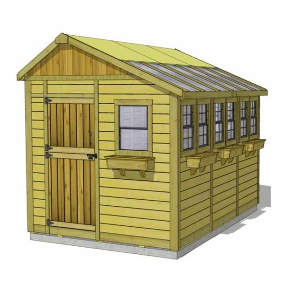
Roof Area: 74sqft
Thank you for purchasing
an 8x12 SunShed Greenhouse
Building from Outdoor Living
Today. Please take the time to
identify all the parts prior to
assembly.
Safety Points and Other Considerations
Our products are built for use based on
proper installation and normal residential
use, on level ground. Please follow the
instruction manual when building your
shed and retain the manual for future
maintenance purposes.
Some of the safety and usage measures you may wish to consider include:
-snow load ratings vary by geographical location. If heavy or wet snowfall occurs, it is advisable to sweep
the snow off the roof(s).
-if the product is elevated, any structural and building code requirements are solely the customer's
responsibility, and should be abided by.
-in high or gusty wind conditions it is advisable to keep the structure securely grounded.
-have a regular maintenance plan to ensure screws, doors, windows and parts are tight.
Customer agrees to hold Outdoor Living Today Partnership and any Authorized Dealers
free of any liability for improper installation, maintenance and repair.
In the event of a missing or broken piece, simply call the Outdoor Living Today Customer
Support Line @ 1-888-658-1658 within 30 days of the delivery of your purchase. It is our
commitment to you to courier replacement parts, free of charge, within 10 business days of
this notification. Replacement parts will not be provided free of charge after the 30 day grace
period.
Toll Free 1-888-658-1658
8x12 SunShed Greenhouse
Building Assembly Manual
Plywood Roof - T&G Model
www.outdoorlivingtoday.com
Reversible Roof Lines
Page 1
Revision #2.2
February 8, 2022
sales@outdoorlivingtoday.com
Advertisement

Related Manuals for OLT SunShed Greenhouse 8x12


Summary of Contents for OLT SunShed Greenhouse 8x12
- Page 1 Revision #2.2 February 8, 2022 8x12 SunShed Greenhouse Building Assembly Manual Plywood Roof - T&G Model Reversible Roof Lines Roof Area: 74sqft Thank you for purchasing an 8x12 SunShed Greenhouse Building from Outdoor Living Today. Please take the time to identify all the parts prior to assembly.
- Page 2 What to do before my Shed arrives? • Become familiar with this assembly manual and determine if you can complete the project yourself or will require a professional contractor. • One helper is recommended to assist in constructing your shed. It generally takes two people over two days to assemble a shed.
- Page 3 Foundation Types for 8x12 Garden Shed 96” 96” 136 1/2” 136 1/2” Completed Foundation Concrete Foundation Floor Frame Concrete Slab Foundation: - Slab must be at least the same size as assembled floor frame (136 1/2” x 96”) or larger. - 6”...
- Page 4 Thank you for purchasing our 8x12 SunShed Greenhouse Building. Please take the time to identify all the parts prior to assembly. A. Floor Section D. Roof Section 3 - 45 1/2” x 75” - Floor Joist Frames (Interior Joist Unattached) 4 - 5/8”...
-
Page 5: Hardware Kit
8x12 SUNSHED HARDWARE SHEET Hardware Kit (Provided) 350 pcs 2 1/2” 174 pcs 2” 1 1/2” 558 pcs Finishing 26 pcs 2” Black Headed 1 1/4” 525 pcs 1 pcs Square Drive Bit 1” 42 pcs Silver 23 pcs 3/4” Silver Single Rafter Double Rafter... - Page 6 Regular Maintenance & Tips to prolong the life of your shed. Before/During Assembly: 1.) Paint each face and edge of your plywood floor with a latex exterior paint. 2.) Caulk wall seams if gaps appear. 3.) Caulk around window framing. 4.) Caulk perimeter between floor plywood and bottom wall plate.
-
Page 7: Floor Section
Exploded view of all parts necessary to A. Floor Section complete Floor Section. Identify all parts prior to starting. Note: Floor Footprint is 96” wide x 136 1/2” deep. Plywood Floor Plywood Floor Large (3) Small (3) Floor Joist Frames Small (3) Floor Joist Floor Runners (10) - Page 8 Attach each large and small floor joist Lay out completed Floor Joist Frames as frame together with 6 - 2 1/2” screws per illustrated. There are 3 larger and 3 smaller section. Frame Sections. The Footprint for the floor when attached together will be 96”...
- Page 9 Foundations Note: The floor will be flipped over and floor runners will sit on your foundation. It is important to note that having a level foundation is critical. Choosing a foundation will vary between regions. Typical foundations can be concrete pads or patio stones positioned underneath the floor runners.
- Page 10 Exploded view of all parts necessary to B. Wall Section complete Wall Section. Identify all parts prior to starting. Solid Walls (4) Gable Walls (2) Top Plates (2) (tall side) Wall Top Plates (2) Solid Walls (1) Extender (short side) Door Header Narrow Wall...
- Page 11 Important: Pilot hole ALL 2x3 Wall Studs with 1/8” drill bit prior to screwing. This will make it much easier to attached together. Pilot Bottom Wall Plate Hole Plate first. Starting with Solid Wall Panels, carefully lay panel face down. Position and attach Wall Plate (1 1/2”...
- Page 12 2x3 wall framing flush with floor framing. Position rear Solid Wall on plywood floor. Butt 45 1/2” wide wall both vertical wall studs of side and rear walls together 34 1/8” wide wall and attach with 5 - 2 1/2” screws. Screw at the bottom, middle and top of stud to secure.
- Page 13 Locate 3 Solid Side Walls and Position and secure Wall Panel studs position on left side. together as per Step 18. Wall panel will sit flush with floor framing at front of shed. Front Side Wall Panel will sit flush with floor framing in corner when positioned correctly. Position Right Side Double Window Wall on floor.
- Page 14 Position remaining Double Window Walls and attach as per Step 20. Place 2nd Window Wall Position and attach Narrow Wall Panel to left side wall stud Panel in front and attach as per with 3 - 2 1/2” screws as per Step 22. Note: Narrow Wall is 73” Step 16.
- Page 15 Dado cut on edge Position and attach the Door Header (2” x 3 1/8” x 45 1/2”) to Door Jamb and Narrow Wall Panel top framing. Header should sit flush with Door Jamb and Outside of Narrow Wall Panel Siding. Attach with 3 - 2 1/2”...
- Page 16 Locate and place Extender Wall on top of Door Header. Align so framing lines up with framing of regular walls. When correctly in place, secure with 3 - 2 1/2” screws. Tip of 33 3/4 degree Top Plate flush with wall framing Flush to inside of wall framing Locate Rear Top Plate (3/4”...
- Page 17 Next, attach the Side Top Plates (1 1/2” x 2 1/2” x 65 3/4” - 33 3/4 degree cut down edge) to high wall side. Once again, position top plate so it is flush with inside of wall plate. Side plate should also be flush with Rear Top Plate.
- Page 18 Offset Brace Seams 27” Repeat Step 34 but Attach Horizontal Wall Extender Braces (3/4” x 3 1/2” x 82 3/4”/48 1/2”) to lower part of the walls approximately 27” up from the floor but offset the seams from previous braces. Attach with 8 - 1 1/4”...
- Page 19 Flashing to overhang wall Straight Edge Triangular Gable Trim attached in Step 70. Lift up Gable Wall and place on top of rear wall. Gable side with 33 3/4” degree cut will be aligned on high wall side. Slide Gable Wall side to side and use a straight edge to line up angled framing of gable with Top Plates and Walls.
- Page 20 C. Rafter Section Exploded view of all parts necessary to complete Rafter and Roof Section. Identify all parts prior to starting. Metal Ridge Board Short Roof Ridge Boards Connectors (2) Rafter (9) Long (2) Ridge Boards Short (2) Facia Nailing Strips (6) Gussets (3) Long Roof...
- Page 21 Ridge Boards Locate 9 Rafters, 2 Soffits and completed Ridge Board. Lay out on level ground as shown to the right. Double up Rafters as illustrated. Screw doubled up Rafters together with 3 - 2 1/2” screws per piece. Note: completed rafter section will be flipped over in Step 42.
- Page 22 Slide Bottom of Ridge Board into notch of gable. gable notch Starting with the Short Rafter Side, lift and flip completed section over so Soffit is facing down. Slide rafter up on gable framing until bottom of Ridge Board slips into gable notch. Position rafters so they sit evenly on Gable framing from side to side.
- Page 23 Offsetting Metal Ridge Board Connectors. Where Ridge Boards meet, press together and secure with 12 -1 1/4” screws. In addition, place 4 - 1 1/4” screws into any of the remaining Metal Ridge Board Connectors holes. Complete both sides. Important: If Gable framing does not line up with Rafters, remove temporary 2”...
- Page 24 With Gusset correctly positioned, attach to Rafter with 4 - 2” screws per side. Use a level to check for square. Pilot hole end of Gussets to prevent splitting. Complete installation of remaining Gussets. 1/4” gap Further secure Cleats with 2 - 1 1/4” screws. Important: Drill pilot holes to prevent splitting!
- Page 25 Outer Centered Short Roof Side Roof and 1/4” Panel 48” back. wide. 2 3/4” past rafter Place Roof Panel so it sits flush on 3rd rafter from the outside (doubled up rafter). Plywood on roof should be flush with end of rafter at bottom. From the outside, screw down through plywood into rafter with 1 - 2 1/2”...
- Page 26 Outside Panel 48” wide. Lift up and place remaining Outside Plywood Roof Panel on rafters. Position and attach as per Steps 55-56. Outside Panel 48” wide x 37 1/2” long. Small Lift and place Outside Plywood Roof Panel (48” wide x 37 1/2” long) on Polygal Roof side. Position on rafters as per Step 54.
- Page 27 Completed Polygal Side Roof Panels Attach center panel as per Step 58. Position remaining Short Outside Roof Panel and attach as per Steps 57. equal gaps on each side of rafter. Installation of 6 Polygal Panels is next. Start by removing protective plastic layer on each panel.
-
Page 28: Miscellaneous Section
E. Miscellaneous Section Expert Advice: When installing trim, sort pieces according to color and pieces that are most pleasing to the eye. Start with least visible side and use the least desirable pieces first. Install trim to most visible sides as your skill installing trim improves. Attach Bottom Skirting around the base of the shed. - Page 29 Align and attach both Narrow and Wide Trims in each corner. Starting with a Narrow Trim (1/2” x 2 1/2” x (2 Short Wall @ 79”) & (2 Tall Wall @ 88”)), align tight underneath Soffit and Rafter. Position flush with Filler Trim so Wide Trim will cap it when attached in Step 69.
- Page 30 87” Rear Wall Narrow Trim Attach remaining Narrow Wall Trims where wall panels come together and leave a seam. Note: the Narrow Trim is 79” long on the Short Wall Side, 88” long on the Tall Wall Side, and 87” on the Rear Wall.
- Page 31 Important: Drill pilot holes with 1/8” drill bit prior to securing Temporarily positioned Interior with screws to prevent wood Vertical Door Stop to help splitting. On 3/4” screw, drill align Interior Barrel Bolt. shallow pilot hole only. 2” Screws 3/4” Screw Attach Door Handle and Exterior Black Drop Latch to door.
- Page 32 Align and attach remaining Ridge Caps (3 1/2” wide) over Double Rafters as per Steps 77 & 78. Edge of plywood roof. Attach Facia Nailing Strips (3/4” x 1 1/2” x 34”) to the outside of plywood roof sheathing using 3- 1 1/4”...
- Page 33 Attach Long Front and Rear Facia (3/4” x 3 1/2” x 78 3/4”) to roof plywood and Outside Ridge Cap edge with 10 - 1 1/2” finishing nails and 2 -1 1/2” screws. Use screws where Outside Ridge Cap and Facia meet. Once again, Line Facia up so it is aligned with rafter ends. Do a dry run with Front, Rear and Side Facia to confirm correct positioning prior to attaching.
- Page 34 Angle cut on 1 end Locate Horizontal Gable Trim Attach both the Horizontal Door Trim (1/2” x 4 1/2” x 85 1/2”) for both front and (1/2” x 2 1/2” x 32”) and Horizontal Narrow rear of shed. Wall Trim (1/2” x 2 1/2” x 8 3/4”) with 4 and 2 finishing nails.
- Page 35 Window frame. Caulk gap. Screw insert into thick part of siding. To reduce possible water from penetrating into the window cavity, caulk gap on both sides of window opening prior to installing Window Insert. Position insert in cavity and screw with 6 - 1 1/4”...
- Page 36 Locate 1 Long Potting Shelf and 1 Leg. Position shelf in corner tight against wall framing. While supporting the shelf, attach shelf with 2 1/2” screw. Place leg underneath shelf and attach to inside shelf frame and wall framing as illustrated above with 2 1/2” screws. Place Short Potting Shelf against wall framing and end of long shelf framing.
- Page 37 Outdoor Living Today Flower Box Assembly Instructions Exploded Side Trims (D) View Front Trim (C) End Caps (B) 1 1/4” Parts Lists: Nails (G) A - Base, Rear & Front Box Frames (3pcs) 3/4” x 5 1/2” x 23” B - End Cap Frames (2pcs) 3/4”...
- Page 38 Congratulations on Completing your 8 x 12 Sunshed! Note: Our buildings are shipped as an unfinished product. If exposed to the elements, the western red cedar lumber will weather to a silvery-gray color. If you prefer to keep the cedar lumber looking closer to the original color, we suggest that you treat the wood with...
Need help?
Do you have a question about the SunShed Greenhouse 8x12 and is the answer not in the manual?
Questions and answers