Sign In
Upload
Manuals
Brands
WAGO Manuals
I/O Systems
750-471
WAGO 750-471 Analog Input Module Manuals
Manuals and User Guides for WAGO 750-471 Analog Input Module. We have
2
WAGO 750-471 Analog Input Module manuals available for free PDF download: Manual
WAGO 750-471 Manual (90 pages)
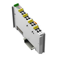
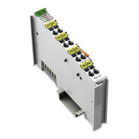
4AI U/I Diff Galv 4-Channel Analog Input; for Voltage/Current
Brand:
WAGO
| Category:
I/O Systems
| Size: 5.61 MB
Table of Contents
Table of Contents
3
Notes about this Documentation
5
Validity of this Documentation
5
Copyrights
5
Copyright
7
Symbols
8
Number Notation
10
Font Conventions
10
Table 1: Number Notation
10
Table 2: Font Conventions
10
Important Notes
11
Legal Bases
11
Subject to Changes
11
Personnel Qualifications
11
Use of the WAGO-I/O-SYSTEM 750 in Compliance with Underlying Provisions
11
Technical Condition of Specified Devices
12
Disposal
12
Safety Advice (Precautions)
13
Device Description
15
Table 3: Compatibility List 750-471
16
View
18
Figure 1: View
18
Table 4: Legend for Figure "View
18
Connectors
19
Data Contacts/Local Bus
19
Figure 2: Data Contacts
19
Power Jumper Contacts/Field Supply
20
Figure 3: Power Jumper Contacts
20
Table 5: Legend for Figure "Power Jumper Contacts
20
Cage Clamp
22
Figure 4: CAGE CLAMP ® Connectors
22
Table 6: Legend for Figure "CAGE CLAMP ® Connectors
22
Display Elements
23
Figure 5: Display Elements
23
Table 7: Legend for Figure "Display Elements
23
Schematic Diagram
25
Figure 6: Schematic Diagram
25
Figure 7: Circuit Diagram
25
Technical Data
26
Device Data
26
Supply
26
Isolation
26
Communication
26
Table 8: Technical Data - Device
26
Table 9: Technical Data - Supply
26
Table 10: Technical Data - Isolation
26
Table 11: Technical Data - Communication
26
Inputs
27
Connection Type
27
Table 12: Technical Data - Inputs
27
Table 13: Technical Data - Field Wiring
27
Table 14: Technical Data - Power Jumper Contacts
27
Table 15: Technical Data - Data Contacts
27
Climatic Environmental Conditions
28
Table 16: Technical Data - Climatic Environmental Conditions
28
Approvals
29
Standards and Guidelines
30
Process Image
31
Overview
31
Table 17: Process Image - I/O Module750-471
32
Status Bytes
33
Table 18: Status Byte CH1_S0
33
Process Data
34
Overview of Sensor Types
34
Table 19: Process Data, Signal Types
34
Table 20: Signal Types "0
35
Table 21: Signal Types "0
36
Signal Types "± 10 V", "± 200 MV" "± 20 Ma", Two's Complement (Default)
37
Table 22: Signal Types "± 10 V", "± 200 MV", "± 20 Ma", Two's Complement
37
Table 23: Signal Types "± 10 V", "± 200 MV" "± 20 Ma", Two's Complement with
38
Table 24: Signal Types "± 10 V", "± 200 MV" "± 20 Ma", Amount/Sign Format
38
Table 25: Signal Types "± 10 V", "± 200 MV" "± 20 Ma", Amount/Sign Format with
39
Signal Type "Namur NE43
40
Table 26: Signal Type "Namur NE43", Two's Complement
40
Table 27: Signal Type "Namur NE43", Two's Complement with Status Information
41
Table 28: Signal Type "Namur NE43", Amount/Sign Format
42
Table 29: Signal Type "Namur NE43", Amount/Sign Format with Status
43
Mounting
44
Mounting Sequence
44
Inserting and Removing Devices
45
Inserting the I/O Module
45
Figure 8: Insert I/O Module (Example)
45
Figure 9: Snap the I/O Module into Place (Example)
45
Removing the I/O Module
46
Figure 10: Removing the I/O Module (Example)
46
Connect Devices
47
Connecting a Conductor to the CAGE CLAMP
47
Figure 11: Connecting a Conductor to a CAGE CLAMP
47
Connection Examples
48
Figure 12: Connection Example 750-471
48
Commissioning
49
Parameterization with WAGO-I/O-CHECK
49
Figure 13: WAGO-I/O-CHECK User Interface
50
Parameterization Dialog
51
Figure 14: Parameterization Dialog 750-471
51
Toolbar on the Configuration Dialog
52
Figure 15: Toolbar
52
Table 30: Toolbar
52
Navigation Area
53
Figure 16: Navigation
53
Table 31: Navigation
53
Common
54
Figure 17: Parameter „Common
54
Table 32: "General" Parameters
54
Channel Settings
56
Figure 18: Parameter „Channel
56
Table 33: Parameter „Channel
56
Scaling
58
Figure 19: Parameter "Scaling
58
Table 34: "Scaling" Parameters
58
Calibration
60
Figure 20: "Calibration" Parameters
61
Table 35: Calibration Parameters
61
Figure 21: Offset Correction
62
Figure 22: Gain Correction
62
Scaling Measured Values
64
Table 36: Variable Legend - Scaling Measured Values
64
Diagnostics
65
I/O Module Behavior in the Event of an Error
65
Table 37: Priority Levels of Diagnostic Functions
65
Table 38: Behavior in the Event of an I/O Module Error Dependent on the
66
Firmware Changes
68
Use in Hazardous Environments
69
Marking Configuration Examples
70
Marking for Europe According to ATEX and Iecex
70
Figure 23: Marking Example According to ATEX and Iecex
70
Figure 24: Text Detail - Marking Example According to ATEX and Iecex
70
Table 39: Description of Marking Example According to ATEX and Iecex
71
Figure 25: Marking Example for Approved Ex I I/O Module According to ATEX
72
Figure 26: Text Detail - Marking Example for Approved Ex I I/O Module
72
Marking for America (NEC) and Canada (CEC)
73
Table 40: Description of Marking Example for Approved Ex I I/O Module According to ATEX and Iecex
73
Table 42: Description of Marking Example for Approved Ex I I/O Module
73
Figure 27: Marking Example According to NEC
74
Figure 28: Text Detail - Marking Example According to NEC 500
74
Table 41: Description of Marking Example According to NEC 500
74
Figure 29: Text Detail - Marking Example for Approved Ex I I/O Module
75
Figure 30: Text Detail - Marking Example for Approved Ex I I/O Module
75
Table 43: Description of Marking Example for Approved Ex I I/O Modules
75
Figure 31: Text Detail - Marking Example for Approved Ex I I/O Modules
76
Table 44: Description of Marking Example for Approved Ex I I/O Modules
76
Installation Regulations
77
Special Notes Regarding Explosion Protection
77
Special Notes Regarding ANSI/ISA Ex
79
Appendix
80
Configuration and Parameterization Using a GSD File with PROFIBUS DP and PROFINET IO
80
4AI U/I Diff/Galv Configuration
80
PROFIBUS DP Fieldbus Couplers/Controllers 750-333(/0Xx-000)
80
750-833(/0Xx-000)
80
PROFINET IO Fieldbus Couplers 750-375(/025-000), 750-377(/025-000)
80
Table 45: PROFIBUS DP Configuration
80
Table 46: Configuration 750-375(/025-000) und 750-377(/025-000)
80
4AI U/I Diff/Galv Parameterization
81
Figure 32: Example of the PROFIBUS DP Fieldbus Couplers/Controllers
81
Figure 33: Example of the Fieldbus Couplers/Controllers Parameterization Dialog
82
All PROFIBUS DP and PROFINET IO Fieldbus Couplers/Controllers
83
Table 47: Specific Module/Channel Parameters for 75X-461/003-000
83
PROFIBUS DP Fieldbus Couplers/Controllers 750-333(/0Xx-000), 750-833(/0Xx-000)
84
PROFINET IO Fieldbus Couplers 750-375(/025-000), 750-377(/025-000)
84
Table 48: General Module/Channel Parameters
84
Table 49: General Module/Channel Parameters
84
List of Figures
87
List of Tables
88
Advertisement
WAGO 750-471 Manual (90 pages)
Brand:
WAGO
| Category:
I/O Systems
| Size: 5.41 MB
Table of Contents
Table of Contents
3
Copyrights
5
Notes about this Documentation
5
Validity of this Documentation
5
Copyright
7
Symbols
8
Number Notation
10
Font Conventions
10
Table 1: Number Notation
10
Table 2: Font Conventions
10
Use of the WAGO-I/O-SYSTEM 750 in Compliance with Underlying Provisions
11
Personnel Qualifications
11
Subject to Changes
11
Legal Bases
11
Important Notes
11
Technical Condition of Specified Devices
12
Disposal
12
Safety Advice (Precautions)
13
Device Description
15
Table 3: Compatibility List 750-471
16
Table 4: Legend for Figure "View
18
Figure 1: View
18
View
18
Data Contacts/Local Bus
19
Figure 2: Data Contacts
19
Connectors
19
Power Jumper Contacts/Field Supply
20
Figure 3: Power Jumper Contacts
20
Table 5: Legend for Figure "Power Jumper Contacts
20
Cage Clamp
22
Figure 4: CAGE CLAMP ® Connectors
22
Table 6: Legend for Figure "CAGE CLAMP ® Connectors
22
Display Elements
23
Figure 5: Display Elements
23
Table 7: Legend for Figure "Display Elements
23
Schematic Diagram
25
Figure 6: Schematic Diagram
25
Figure 7: Circuit Diagram
25
Table 8: Technical Data - Device
26
Table 10: Technical Data - Isolation
26
Table 11: Technical Data - Communication
26
Table 9: Technical Data - Supply
26
Supply
26
Communication
26
Device Data
26
Technical Data
26
Isolation
26
Table 13: Technical Data - Field Wiring
27
Table 15: Technical Data - Data Contacts
27
Table 14: Technical Data - Power Jumper Contacts
27
Table 12: Technical Data - Inputs
27
Connection Type
27
Inputs
27
Climatic Environmental Conditions
28
Table 16: Technical Data - Climatic Environmental Conditions
28
Approvals
29
Standards and Guidelines
30
Process Image
31
Overview
31
Table 17: Process Image - I/O Module750-471
32
Table 18: Status Byte CH1_S0
33
Status Bytes
33
Process Data
34
Overview of Sensor Types
34
Table 19: Process Data, Signal Types
34
Table 20: Signal Types "0
35
Table 21: Signal Types "0
36
Signal Types "± 10 V", "± 200 MV" "± 20 Ma", Two's Complement (Default)
37
Table 22: Signal Types "± 10 V", "± 200 MV", "± 20 Ma", Two's Complement
37
Table 24: Signal Types "± 10 V", "± 200 MV" "± 20 Ma", Amount/Sign Format
38
Table 23: Signal Types "± 10 V", "± 200 MV" "± 20 Ma", Two's Complement with
38
Table 25: Signal Types "± 10 V", "± 200 MV" "± 20 Ma", Amount/Sign Format with
39
Signal Type "Namur NE43
40
Table 26: Signal Type "Namur NE43", Two's Complement
40
Table 27: Signal Type "Namur NE43", Two's Complement with Status Information
41
Table 28: Signal Type "Namur NE43", Amount/Sign Format
42
Table 29: Signal Type "Namur NE43", Amount/Sign Format with Status
43
Mounting
44
Mounting Sequence
44
Figure 9: Snap the I/O Module into Place (Example)
45
Figure 8: Insert I/O Module (Example)
45
Inserting the I/O Module
45
Inserting and Removing Devices
45
Removing the I/O Module
46
Figure 10: Removing the I/O Module (Example)
46
Connect Devices
47
Connecting a Conductor to the CAGE CLAMP
47
Figure 11: Connecting a Conductor to a CAGE CLAMP
47
Connection Examples
48
Figure 12: Connection Example 750-471
48
Parameterization with WAGO-I/O-CHECK
49
Commissioning
49
Figure 13: WAGO-I/O-CHECK User Interface
50
Parameterization Dialog
51
Figure 14: Parameterization Dialog 750-471
51
Toolbar on the Configuration Dialog
52
Figure 15: Toolbar
52
Table 30: Toolbar
52
Navigation Area
53
Figure 16: Navigation
53
Table 31: Navigation
53
Table 32: "General" Parameters
54
Common
54
Figure 17: Parameter „Common
54
Channel Settings
56
Figure 18: Parameter „Channel
56
Table 33: Parameter „Channel
56
Scaling
58
Figure 19: Parameter "Scaling
58
Table 34: "Scaling" Parameters
58
Calibration
60
Table 35: Calibration Parameters
61
Figure 20: "Calibration" Parameters
61
Figure 21: Offset Correction
62
Figure 22: Gain Correction
62
Scaling Measured Values
64
Table 36: Variable Legend - Scaling Measured Values
64
Diagnostics
65
I/O Module Behavior in the Event of an Error
65
Table 37: Priority Levels of Diagnostic Functions
65
Table 38: Behavior in the Event of an I/O Module Error Dependent on the
66
Firmware Changes
68
Use in Hazardous Environments
69
Marking Configuration Examples
70
Figure 23: Marking Example According to ATEX and Iecex
70
Figure 24: Text Detail - Marking Example According to ATEX and Iecex
70
Marking for Europe According to ATEX and Iecex
70
Table 39: Description of Marking Example According to ATEX and Iecex
71
Figure 25: Marking Example for Approved Ex I I/O Module According to ATEX
72
Figure 26: Text Detail - Marking Example for Approved Ex I I/O Module
72
Marking for America (NEC) and Canada (CEC)
73
Table 40: Description of Marking Example for Approved Ex I I/O Module According to ATEX and Iecex
73
Table 42: Description of Marking Example for Approved Ex I I/O Module
73
Table 41: Description of Marking Example According to NEC 500
74
Figure 27: Marking Example According to NEC
74
Figure 28: Text Detail - Marking Example According to NEC 500
74
Figure 29: Text Detail - Marking Example for Approved Ex I I/O Module
75
Figure 30: Text Detail - Marking Example for Approved Ex I I/O Module
75
Table 43: Description of Marking Example for Approved Ex I I/O Modules
75
Figure 31: Text Detail - Marking Example for Approved Ex I I/O Modules
76
Table 44: Description of Marking Example for Approved Ex I I/O Modules
76
Installation Regulations
77
Special Notes Regarding Explosion Protection
77
Special Notes Regarding ANSI/ISA Ex
79
Appendix
80
Configuration and Parameterization Using a GSD File with PROFIBUS DP and PROFINET IO
80
4AI U/I Diff/Galv Configuration
80
PROFIBUS DP Fieldbus Couplers/Controllers 750-333(/0Xx-000)
80
750-833(/0Xx-000)
80
PROFINET IO Fieldbus Couplers 750-375(/025-000), 750-377(/025-000)
80
Table 45: PROFIBUS DP Configuration
80
Table 46: Configuration 750-375(/025-000) und 750-377(/025-000)
80
Figure 32: Example of the PROFIBUS DP Fieldbus Couplers/Controllers
81
4AI U/I Diff/Galv Parameterization
81
Figure 33: Example of the Fieldbus Couplers/Controllers Parameterization Dialog 750-375(/025-000) and 750-377(/025-000)
82
All PROFIBUS DP and PROFINET IO Fieldbus Couplers/Controllers
83
Table 47: Specific Module/Channel Parameters for 75X-461/003-000
83
PROFIBUS DP Fieldbus Couplers/Controllers 750-333(/0Xx-000), 750-833(/0Xx-000)
84
PROFINET IO Fieldbus Couplers 750-375(/025-000), 750-377(/025-000)
84
Table 48: General Module/Channel Parameters
84
Table 49: General Module/Channel Parameters
84
List of Figures
87
List of Tables
88
Advertisement
Related Products
WAGO I/O-SYSTEM 750-478
WAGO 750-479
WAGO 750-471/040-000
WAGO 750-454/000-200
WAGO 750-454/000-002
WAGO 750-402
WAGO WAGO-I/O-SYSTEM 750-424
WAGO IO-SYSTEM 750-415
WAGO 750-462 Series
WAGO 750-462/000-001
WAGO Categories
I/O Systems
Control Unit
Power Supply
Switch
Controller
More WAGO Manuals
Login
Sign In
OR
Sign in with Facebook
Sign in with Google
Upload manual
Upload from disk
Upload from URL