Table of Contents
Advertisement
Advertisement
Table of Contents

Subscribe to Our Youtube Channel
Related Manuals for Supermicro C9X299-PGF-L


Summary of Contents for Supermicro C9X299-PGF-L
- Page 1 C9X299-PGF-L C9X299-RPGF-L USER'S MANUAL Revision 1.0...
- Page 2 State of California, USA. The State of California, County of Santa Clara shall be the exclusive venue for the resolution of any such disputes. Supermicro's total liability for all claims will not exceed the price paid for the hardware product.
- Page 3 About This Manual This manual is written for system integrators, IT technicians and knowledgeable end users. It provides information for the installation and use of the C9X299-PGF-L/-RPGF-L motherboard. About This Motherboard The C9X299-PGF-L/-RPGF-L motherboard supports a single Intel® Core™ X-series processor family in an LGA2066 R4 socket.
- Page 4 Super C9X299-PGF-L/-RPGF-L User's Manual Contacting Supermicro Headquarters Address: Super Micro Computer, Inc. 980 Rock Ave. San Jose, CA 95131 U.S.A. Tel: +1 (408) 503-8000 Fax: +1 (408) 503-8008 Email: marketing@supermicro.com (General Information) support@supermicro.com (Technical Support) Website: www.supermicro.com Europe Address: Super Micro Computer B.V.
-
Page 5: Table Of Contents
Preface Table of Contents Chapter 1 Introduction 1.1 Checklist ..........................8 Quick Reference .......................13 Quick Reference Table ......................14 Motherboard Features .......................16 1.2 Chipset Overview .......................20 1.3 Special Features ........................20 Recovery from AC Power Loss ..................20 1.4 System Health Monitoring ....................20 Onboard Voltage Monitors ....................20 Fan Status Monitor with Firmware Control ...............21 Environmental Temperature Control .................21 System Resource Alert......................21... - Page 6 Super C9X299-PGF-L/-RPGF-L User's Manual 2.4 Memory Support and Installation ..................32 General Guidelines for Optimizing Memory Performance ..........32 DIMM Installation ......................33 DIMM Removal .........................33 Memory Population Guidelines ..................34 2.5 M.2 Installation (optional) ....................35 2.6 Rear I/O Ports ........................36 2.7 Front Control Panel ......................40 2.8 Connectors .........................45...
- Page 7 Preface Chapter 4 UEFI BIOS 4.1 Introduction .........................69 4.2 EZ Mode ..........................71 4.3 Overclocking ........................72 4.4 CPU ............................87 4.5 Memory ..........................91 4.6 Advanced ..........................92 4.7 IPMI ........................... 111 4.8 BOOT ..........................115 4.9 BIOS Update ........................117 Appendix A BIOS Codes A.1 BIOS Error POST (Beep) Codes ..................118 A.2 Additional BIOS POST Codes ..................119 Appendix B Software B.1 Microsoft Windows OS Installation ...................120...
-
Page 8: Chapter 1 Introduction
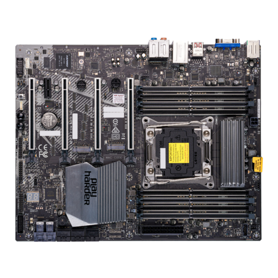
Introduction Congratulations on purchasing your computer motherboard from an industry leader. Supermicro motherboards are designed to provide you with the highest standards in quality and performance. In addition to the motherboard, several important parts that are included in the retail box are listed below. - Page 9 Chapter 1: Introduction Figure 1-1. C9X299-PGF-L Motherboard Image Differences between C9X299-PGF-L and C9X299-RPGF-L C9X299-PGF-L C9X299-RPGF-L High Definition Audio Ports (back panel) Note: All graphics shown in this manual were based upon the latest PCB revision avail- able at the time of publication of the manual. The motherboard you received may or...
- Page 10 Super C9X299-PGF-L/-RPGF-L User's Manual Figure 1-2. C9X299-RPGF-L Motherboard Image Differences between C9X299-PGF-L and C9X299-RPGF-L C9X299-PGF-L C9X299-RPGF-L High Definition Audio Ports (back panel) Note: All graphics shown in this manual were based upon the latest PCB revision avail- able at the time of publication of the manual. The motherboard you received may or...
- Page 11 Chapter 1: Introduction Figure 1-3. C9X299-PGF-L Motherboard Layout (not drawn to scale) J3701 JCOM1 MH15 HD AUDIO KB/Mouse USB 4/5(3.0) LAN1 USB 8/9 (3.1) USB 6/7(3.1) JPB1 MH12 SYS_FAN3 SYS_FAN2 MH14 DIMMB1 DIMMB2 DIMMA1 BAR CODE DIMMA2 IPMI CODE BIOS...
- Page 12 DIMMC2 DIMMC1 DIMMD2 DIMMD1 JSD1 U.2-1 U.2-2 SYS_FAN1 CPU_FAN2 JPW1 JLED1 JPI2C1 I-SATA2 I-SATA0 I-SATA4 I-SATA5 I-SATA3 I-SATA1 Differences between C9X299-PGF-L and C9X299-RPGF-L C9X299-PGF-L C9X299-RPGF-L High Definition Audio Ports (back panel) Note: Components not documented are for internal testing only.
-
Page 13: Quick Reference
Chapter 1: Introduction Quick Reference JIPMB1 JPG1 MH15 JPAC1 J3701 LAN1 KB/Mouse USB8 USB4 SLOT2 SLOT7 SYS_ LED6904 SLOT5 FAN3 HD AUDIO USB9 USB6 USB5 SLOT1 SLOT3 MH14 MH12 USB7 J3701 JCOM1 MH15 HD AUDIO KB/Mouse JCOM1 USB 4/5(3.0) LAN1 USB 8/9 (3.1) USB 6/7(3.1) JPB1... -
Page 14: Quick Reference Table
CPU SLOT 1/3/5 PCI-E 3.0 x8 (IN x16) PCIe 3.0 x8 (IN x16) Slots CPU SLOT 7 PCI-E 3.0 x16 PCIe 3.0 x16 Slot HD AUDIO High Definition Audio Header (C9X299-PGF-L only) I-SATA0~5 (Intel X299) Serial ATA (SATA 3.0) Ports 0~5 (6Gb/sec) J3701 Front Panel Audio Header... - Page 15 Chapter 1: Introduction Connector Description JSTBY1 Standby Power Header JTPM1 Trusted Platform Module (TPM)/Port 80 Header KB/MOUSE PS/2 Keyboard/Mouse Port LAN1 1Gb LAN Port (Shared IPMI Port) MH12, MH14, MH15 M.2 Mounting Holes PCIe 3.0 x4 M.2 Connector (M-Key 22110 and 2280 form factors) PCI-E M.2-M1 (Small form factor devices and other portable devices for high speed NVMe SSDs) PCI-E M.2-M2...
-
Page 16: Motherboard Features
Super C9X299-PGF-L/-RPGF-L User's Manual Motherboard Features Motherboard Features • Supports a single Intel Core X-series processor family in an LGA2066 R4 type socket Memory • Supports up to 256GB of unbuffered, non-ECC, DDR4 memory with speeds of up to 3000+MHz (OC) Note 1: To safely overclock your system, make sure to use an overclocked processor. - Page 17 Chapter 1: Introduction Motherboard Features BIOS • 256Mb AMI BIOS SPI Flash BIOS ® • DMI 2.8, PCI 3.0, ACPI 3.0, BIOS rescue hot-key, SPI dual/quad speed support, Overclock support Power Management • ACPI power management • Power button override mechanism •...
- Page 18 Super C9X299-PGF-L/-RPGF-L User's Manual KBL_16 C9X299-PGF-L 16 Lanes Block Diagram SMBUS KBL-X : IMVP8 SMBUS SKX-X : VR13 SLOT1 NA SVID DDR4 (2DPC) Non-ECC UDIMM PCIe3.0_x4 U.2 NA DIMMA0 PE3 0~3 PCIe3.0_x4 DIMMA1 Not Supported U.2 PCIe3.0_x4 PE3 12~15 Intel...
- Page 19 Chapter 1: Introduction SKL_44 C9X299-PGF-L 44/48 Lanes Block Diagram SMBUS SMBUS KBL-X : IMVP8 SKX-X : VR13 PCIe3.0_x8 SVID DDR4 (2DPC) PE3 0~7 PCIe3.0_x8 SLOT1 X8, NA Non-ECC UDIMM PE3 0~7 DIMMA0 SWITCH PCIe3.0_x4 8.0GT/s DIMMA1 PE3 0~3 Intel U.2 PCIe3.0_x4 PCIe3.0_x4...
-
Page 20: Chipset Overview
Super C9X299-PGF-L/-RPGF-L User's Manual 1.2 Chipset Overview The Intel PCH X299 chipset provides support, including the following features: • Direct Media Interface (up 10 Gb/s transfer, Full Duplex) • Intel Matrix Storage Technology and Intel Rapid Storage Technology • Dual NAND Interface •... -
Page 21: Fan Status Monitor With Firmware Control
Windows operating systems. For detailed information regarding OS support, please refer to the Supermicro website. Slow Blinking LED for Suspend-state Indicator When the CPU goes into a suspend state, the chassis power LED will start to blink to indicate that the CPU is in suspend mode. -
Page 22: Power Supply
It is even more important for processors that have high CPU clock rates where noisy power transmission is present. The C9X299-PGF-L/-RPGF-L motherboard accommodates a 24-pin ATX power supply. Although most power supplies generally meet the specifications required by the CPU, some are inadequate. -
Page 23: Chapter 2 Installation
Chapter 2: Installation Chapter 2 Installation 2.1 Static-Sensitive Devices Electrostatic Discharge (ESD) can damage electronic components including memory modules. To avoid damaging your motherboard or your system, it is important to handle them very carefully. The following measures are generally sufficient to protect your equipment from ESD. Precautions •... -
Page 24: Processor And Heatsink Installation
Thermal grease is pre-applied on a new heatsink. No additional thermal grease is needed. • Refer to the Supermicro website for updates on processor support. • All graphics in this manual are for illustrations only. Your components may look different. - Page 25 Chapter 2: Installation 2. There are two load levers on the LGA2066 socket. To open the socket cover, press and release the load lever labeled "Open 1st". Press down on Load Lever labeled 'Open 1st' 3. Press the second load lever labeled "Close 1st" to release the load plate that covers the CPU socket from its locking position.
- Page 26 Super C9X299-PGF-L/-RPGF-L User's Manual 5. Use your thumb and index finger to hold the CPU on its edges. Align the CPU keys, which are semi-circle cutouts, against the socket keys. Socket Keys CPU Keys 6. Once they are aligned, carefully lower the CPU straight down into the socket. To avoid damaging the CPU or socket, do not drop the CPU onto the socket, move it horizontally or vertically, or rub it against the socket pins.
- Page 27 Chapter 2: Installation 8. Close the load plate with the CPU inside the socket. Lock the "Close 1st" lever first, then lock the "Open 1st" lever second. Gently push the load levers down to the lever locks. Gently close the Push down and lock load plate 'Close 1st' lever...
-
Page 28: Installing A Cpu Heatsink
Super C9X299-PGF-L/-RPGF-L User's Manual Installing a CPU Heatsink 1. Apply the proper amount of thermal grease to the heatsink. 2. Place the heatsink on top of the CPU so that the four mounting holes on the heatsink are aligned with those on the retention mechanism. Tighten the screws in the following... -
Page 29: Removing A Cpu Heatsink
Chapter 2: Installation Removing a CPU Heatsink Warning: We do not recommend that the CPU or heatsink be removed. However, if you do need to remove the heatsink, please follow the instruction below to uninstall the heatsink to avoid damaging the CPU or other components. 1. -
Page 30: Motherboard Installation
Super C9X299-PGF-L/-RPGF-L User's Manual 2.3 Motherboard Installation All motherboards have standard mounting holes to fit different types of chassis. Make sure that the locations of all the mounting holes for both the motherboard and the chassis match. Although a chassis may have both plastic and metal mounting fasteners, metal ones are highly recommended because they ground the motherboard to the chassis. -
Page 31: Installing The Motherboard
Chapter 2: Installation Installing the Motherboard 1. Install the I/O shield into the back of the chassis, if applicable. 2. Locate the mounting holes on the motherboard. Refer to the previous page for the location. 3. Locate the matching mounting holes on the chassis. Align the mounting holes on the motherboard against the mounting holes on the chassis. -
Page 32: Memory Support And Installation
Super C9X299-PGF-L/-RPGF-L User's Manual 2.4 Memory Support and Installation Note: Check the Supermicro website for recommended memory modules. Important: Exercise extreme care when installing or removing DIMM modules to pre- vent any possible damage. General Guidelines for Optimizing Memory Performance •... -
Page 33: Dimm Installation
Chapter 2: Installation DIMM Installation J3701 JCOM1 MH15 1. Insert DIMM modules in the following HD AUDIO KB/Mouse USB 4/5(3.0) LAN1 USB 8/9 (3.1) USB 6/7(3.1) JPB1 MH12 order: DIMMA1, DIMMB1, DIMMC1, SYS_FAN3 SYS_FAN2 MH14 DIMMB1 DIMMD1, then DIMMA2, DIMMB2, DIMMB2 DIMMA1 BAR CODE... -
Page 34: Memory Population Guidelines
Super C9X299-PGF-L/-RPGF-L User's Manual Memory Population Guidelines When installing memory modules, always use DDR4 DIMM modules of the same size, type, and speed. Mixed DIMM speeds can be installed. However, all DIMMs will run at the speed of the slowest DIMM. -
Page 35: Installation (Optional)
Chapter 2: Installation 2.5 M.2 Installation (optional) Two M.2 (M-key) connectors are supported by the C9X299-PGF-L/-RPGF-L. M.2 devices are used for solid state storage and internal expansion. Follow the steps below in order to install an M.2 device. Note: The steps below are examples of the M.2 installation, the motherboard you received may or may not look exactly the same. -
Page 36: Rear I/O Ports
JPW1 JLED1 JPI2C1 I-SATA2 I-SATA0 I-SATA4 I-SATA5 I-SATA3 I-SATA1 Figure 2-1. C9X299-PGF-L I/O Port Locations and Definitions Rear I/O Ports Description Description Description PS2 KB/Mouse USB7: 3.2 Gen 2 (Type A) 11. Surround Out USB4: 3.2 Gen 1 (Type A) LAN1 (Shared IPMI Port) 12. - Page 37 Chapter 2: Installation Universal Serial Bus (USB) Ports Two USB 3.2 Gen 1 ports (USB4/5), four USB 3.2 Gen 2 ports (USB6/7/8: Type-A, USB9: Type-C) are on the rear I/O panel. Additionally, two USB 2.0 headers (USB0/1, USB2/3) and one USB 3.2 Gen 1 header (USB10/11) are located on the motherboard to provide front chassis access using USB cables (not included).
- Page 38 A legacy 15-pin VGA port is located on the rear I/O panel to provide backward compatibility. Use this port to connect to a compatible VGA monitor. Back Panel High Definition Audio (C9X299-PGF-L only) This motherboard features a 7.1+2 Channel High Definition Audio (HDA) codec that provides 10 DAC channels.
- Page 39 Chapter 2: Installation LAN Port One RJ45 Ethernet LAN port (LAN1) is located on the rear I/O panel to provide network connection. This port accepts RJ45 type cable. Note: Please refer to Section 2.10 for LAN LED information. LAN1 Port Pin Definition Pin# Definition...
-
Page 40: Front Control Panel
JF1 contains header pins for various buttons and indicators that are normally located on a control panel at the front of the chassis. These connectors are designed specifically for use with Supermicro chassis. Refer to the figure below for the descriptions of the front control panel buttons and LED indicators. - Page 41 Chapter 2: Installation Power Button The Power Button connection is located on pins 1 and 2 of JF1. Momentarily contacting both pins will power on/off the system. This button can also be configured to function as a suspend button (with a setting in the BIOS - refer to Chapter 4).
- Page 42 Super C9X299-PGF-L/-RPGF-L User's Manual Power Fail LED The Power Fail LED connection is located on pins 5 and 6 of JF1. Refer to the table below for pin definitions. Power Fail LED Pin Definitions (JF1) Pin# Definition No Connection Power Fail...
- Page 43 Chapter 2: Installation NIC1 Activity LED The Network Interface Controller (NIC) LED connection for LAN port 1 is located on pins 9 and 10 of JF1. Attach NIC LED cable to NIC1 LED indicators to display network activity. Refer to the table below for pin definitions. NIC1 LED Pin Definitions (JF1) Pin#...
- Page 44 Super C9X299-PGF-L/-RPGF-L User's Manual HDD LED The HDD LED connection is located on pins 13 and 14 of JF1. Attach a cable here to indicate the status of HDD-related activities, including IDE and SATA activities. Refer to the table below for pin definitions.
-
Page 45: Connectors
Chapter 2: Installation 2.8 Connectors This section provides brief descriptions and pinout definitions for onboard headers and connectors. Be sure to use the correct cable for each header or connector. Power Connections ATX Main Power and CPU PWR Connectors The 24-pin main power connector (JPW1) provides power to the motherboard. The 8-pin CPU PWR connector (JPW2) is also required for the processor. -
Page 46: Headers
Super C9X299-PGF-L/-RPGF-L User's Manual Headers Fan Headers The motherboard has five 4-pin fan headers (CPU_Fan1/2 and SYS_Fan1/2/3). Although pins 1-3 of the fan headers are backward compatible with the traditional 3-pin fans, we recommend using 4-pin fans to take advantage of the fan speed control. This allows the fan speeds to be automatically adjusted based on the motherboard temperature. - Page 47 Chapter 2: Installation Internal Speaker/Buzzer The Internal Speaker/Buzzer (SP1) is used to provide audible indications for various beep codes. Refer to the table below for pin definitions. Internal Speaker/Buzzer Pin Definitions Pin# Definition Pos (+) Beep In Neg (-) Alarm Speaker Speaker Header On the JD1 header, pins 3-4 are used for a buzzer.
- Page 48 Super C9X299-PGF-L/-RPGF-L User's Manual Serial Port There is one serial (COM) header on the motherboard. JCOM1 is located next to the PCIe slot 1. Refer to the table below for pin definitions. Serial Port Pin Definitions Pin# Definition Pin# Definition...
- Page 49 Chapter 2: Installation DOM PWR Connector The Disk-On-Module (DOM) power connector is located at JSD1, provides 5V power to a solid state DOM storage device connected to one of the SATA ports. Refer to the table below for pin definitions. DOM PWR Connector Pin Definitions Pin#...
- Page 50 Super C9X299-PGF-L/-RPGF-L User's Manual M.2 Connectors M.2 was formerly known as Next Generation Form Factor (NGFF). The two M.2 connectors are designed for internal mounting devices, and provide M-Key 2280/22120 (PCIe M.2-M1) and 2280 (PCIe M.2-M2) dedicated support for SSD devices with the ultimate performance capability in a PCI Express 3.0 interface for native PCIe SSD support.
- Page 51 Parallel ATA. Refer to the table below for pin definitions. Note: For more information on the SATA HostRAID configuration, please refer to the Intel SATA HostRAID user's guide posted on our website at https://www.supermicro. com/support/manuals/. SATA 3.0 Ports Pin Definitions...
- Page 52 Super C9X299-PGF-L/-RPGF-L User's Manual Front Panel Audio Header A 10-pin Audio header at J3701 is supported on the motherboard. This header allows you to connect the motherboard to a front panel audio control panel, if needed. Connect an audio cable to the audio header to use this feature (not supplied). Refer to the table below for pin definitions.
- Page 53 Chapter 2: Installation TPM Header/Port 80 A Trusted Platform Module/Port 80 header is located at JTPM1 to provide TPM support and Port 80 connection. Use this header to enhance system performance and data security. Refer to the table below for pin definitions. TPM/Port 80 Header Pin Definitions Pin#...
- Page 54 Super C9X299-PGF-L/-RPGF-L User's Manual Power SMB (I C) Header Power System Management Bus header at JPI C1 monitors the power supply, fan and system temperatures. Refer to the table below for pin definitions. Power SMB I C Header Pin Definitions...
-
Page 55: Jumper Settings
Chapter 2: Installation 2.9 Jumper Settings How Jumpers Work To modify the operation of the motherboard, jumpers can be used to choose between optional settings. Jumpers create shorts between two pins to change the function of the connector. Pin 1 is identified with a square solder pad on the printed circuit board. Refer to the diagram below for an example of jumping pins 1 and 2. - Page 56 Super C9X299-PGF-L/-RPGF-L User's Manual Clear CMOS Button & JBT1 Clear CMOS and JBT1 are used to clear the saved system setup configuration stored in the CMOS chip. To clear the contents of the CMOS using JBT1, short the two pads of JBT1 with a metallic conductor such as a flathead screwdriver.
- Page 57 Chapter 2: Installation Manufacturing Mode Close pins 2-3 of jumper JPME2 to by-pass SPI flash security and force the system to operate in Manufacturing Mode, allowing you to flash the system firmware from a host server for system setting modifications. Refer to the table below for jumper settings. Manufacturing Mode Jumpers Settings Jumper Setting...
- Page 58 Super C9X299-PGF-L/-RPGF-L User's Manual Audio Enable/Disable JPAC1 allows you to enable or disable the onboard audio support. The default position is on pins 1-2 to enable onboard audio connections. Refer the table below for jumper settings. Audio Enable/Disable Jumpers Settings...
- Page 59 Chapter 2: Installation BMC Enable/Disable JPB1 allows you to enable or disable the Baseboard Management Control (BMC) chip and the onboard IPMI connection for remote system management/monitoring purpose. This jumper is used together with the IPMI settings in the BIOS. After the BMC is disabled, IPMI health monitoring and remote management functions are no longer supported.
-
Page 60: Led Indicators
Super C9X299-PGF-L/-RPGF-L User's Manual 2.10 LED Indicators LAN1 LEDs The LED on the right indicates activity, and the LED on the left indicates the speed of the connection. Refer to the tables below for more information. LAN1 Speed LED (Left) - Page 61 LED4 is made up of two alpha-numeric displays that will display a status or BIOS POST code, when the motherboard is powered on. For more information, refer to https://www.supermicro.com/manuals/other/AMI_AptioV_BIOS_POST_ Codes_for_SM_Motherboards.pdf. M.2 LED Two M.2 LEDs are provided and indicated the status of connected M.2 devices. When a M.2 LED is blinking, it's corresponding M.2 device function normally.
-
Page 62: Chapter 3 Troubleshooting
Super C9X299-PGF-L/-RPGF-L User's Manual Chapter 3 Troubleshooting 3.1 Troubleshooting Procedures Use the following procedures to troubleshoot your system. If you have followed all of the procedures below and still need assistance, refer to the ‘Technical Support Procedures’ and/ or ‘Returning Merchandise for Service’ section(s) in this chapter. Always disconnect the AC power cord before adding, changing or installing any non hot-swap hardware components. -
Page 63: No Video
Chapter 3: Troubleshooting No Video 1. If the power is on, but you have no video, remove all add-on cards and cables. 2. Use the speaker to determine if any beep codes are present. Refer to Appendix A details on beep codes. 3. -
Page 64: Losing The System's Setup Configuration
Super C9X299-PGF-L/-RPGF-L User's Manual Losing the System's Setup Configuration 1. Make sure that you are using a high-quality power supply. A poor-quality power supply may cause the system to lose the CMOS setup information. Refer to Section 1.6 Power Supply in Chapter 1 for details on recommended power supplies. -
Page 65: Technical Support Procedures
Before contacting Technical Support, please take the following steps. Also, please note that as a motherboard manufacturer, Supermicro also sells motherboards through its channels, so it is best to first check with your distributor or reseller for troubleshooting services. They should know of any possible problems with the specific system configuration that was sold to you. -
Page 66: Frequently Asked Questions
Note: The SPI BIOS chip used on this motherboard cannot be removed. Send your moth- erboard back to our RMA Department at Supermicro for repair. For BIOS Recovery instruc- tions, please refer to the AMI BIOS Recovery Instructions posted at http://www.supermi-... -
Page 67: Battery Removal And Installation
Chapter 3: Troubleshooting 3.4 Battery Removal and Installation Battery Removal To remove the onboard battery, follow the steps below: 1. Power off your system and unplug your power cable. 2. Locate the onboard battery as shown below. 3. Using a tool such as a pen or a small screwdriver, push the battery lock outwards to unlock it. -
Page 68: Returning Merchandise For Service
Super C9X299-PGF-L/-RPGF-L User's Manual 3.5 Returning Merchandise for Service A receipt or copy of your invoice marked with the date of purchase is required before any warranty service will be rendered. You can obtain service by calling your vendor for a Returned Merchandise Authorization (RMA) number. -
Page 69: Chapter 4 Uefi Bios
When a submenu is selected in the left frame, the text becomes blue. Often a text message will accompany it. (Note: the AMI BIOS has default text messages built in. Supermicro retains the option to include, omit, or change any of these text messages.) The AMI BIOS setup utility uses a key-based navigation system called "hot keys". - Page 70 Super C9X299-PGF-L/-RPGF-L User's Manual How To Change the Configuration Data The configuration data that determines the system parameters may be changed by entering the AMI BIOS GUI Setup utility. This Setup utility can be accessed by pressing <Del> at the appropriate time during system boot.
-
Page 71: Ez Mode
Chapter 4: UEFI BIOS 4.2 EZ Mode While in EZ Mode, the following information will be displayed: • DRAM Status - Status of all DIMM slots • CPU Profile Load - Allows for quick CPU clocking profile selection • X.M.P. Profile Load - Allows for quick memory clocking profile selection •... -
Page 72: Overclocking
Super C9X299-PGF-L/-RPGF-L User's Manual 4.3 Overclocking CPU Overclocking CPU Overclocking All Core OC Setting This feature controls the CPU overclocking settings. The options are Manual, 3.8GHz, 3.9GHz, 4.0GHz, 4.1GHz, 4.2GHz, 4.3GHz, 4.4GHz, 4.5GHz, 4.6GHz, 4.7GHz, 4.8GHz, 4.9GHz, 5.0GHz, 5.1GHz, and 5.2GHz. - Page 73 Chapter 4: UEFI BIOS Core Voltage Mode This feature controls the core voltage mode. The options are Adaptive and Override. Core Extra Turbo Voltage (mV) Enter a numeric value for the extra turbo voltage (in mV) that will be applied while IA Core is operating in turbo mode.
- Page 74 Super C9X299-PGF-L/-RPGF-L User's Manual Boot performance mode This feature controls the performance state that the BIOS will set initially. The options are Max Performance and Max Efficient. Energy Efficient Turbo Select Enable to activate Energy Efficient Turbo. This feature will opportunistically lower the turbo frequency to increase efficiency.
- Page 75 Chapter 4: UEFI BIOS PL1 Time Window Enter a value for PL1 Time Window. The default is 1. PL2 Limit This feature enables the PL2 limit. If this feature is set to Disable, a default will be pro- grammed by the BIOS. The options are Disable and Enable. PL2 Power Limit Enter a value for PL2 Power Limit.
- Page 76 Super C9X299-PGF-L/-RPGF-L User's Manual Scalability This feature enables the use of Scalability in HWP p-code power efficiency algorithms. The options are Disable and Enable. PPO-Budget This feature enables PPO-Budget, which allocates power to cores based on their scal- ability/EPP. The options are Disable and Enable.
- Page 77 Chapter 4: UEFI BIOS Memory Voltage (mV) Enter a value for Memory Voltage. To select 1.200 volts, enter 1200. The default is 1200. 1st memory timing: This feature configures the Cas Latency Range. Enter a number between 4-18. The default is 15.
- Page 78 Super C9X299-PGF-L/-RPGF-L User's Manual tFAW This feature selects the Minimum Four Activate Window Delay Time. Enter a numeric value between 1-586. The default is 23. tCWL This feature selects the Minimum CAS Write Latency Time. Enter a numeric value. The default is 14.
- Page 79 Chapter 4: UEFI BIOS tRRDR Enter a value for desired tRRDR. The default is 2. tRRDD Enter a value for desired tRRDD. The default is 2. tRWSR Enter a value for desired tRWSR. The default is 4. tRWDS Enter a value for desired tRWDS. The default is 5. tRWDR Enter a value for desired tRWDR.
- Page 80 Super C9X299-PGF-L/-RPGF-L User's Manual RTL (CHB DIMM2) Enter a value for desired RTL (CHB DIMM2). The default is 0. RTL (CHC DIMM1) Enter a value for desired RTL (CHC DIMM1). The default is 79. RTL (CHC DIMM2) Enter a value for desired RTL (CHC DIMM2). The default is 0.
- Page 81 Chapter 4: UEFI BIOS CHA DIMM1 RTT_Prk Enter a value for desired CHA DIMM1 RTT_Prk. The options are Auto, Disable, 60, 80, 120, 240, and Infinity. CHA DIMM1 RTT_NOM Enter a value for desired CHA DIMM1 RTT_NOM. The options are Auto, Disable, 60, 80, 120, 240, and Infinity.
- Page 82 Super C9X299-PGF-L/-RPGF-L User's Manual CHB DIMM2 RTT_NOM Enter a value for desired CHB DIMM2 RTT_NOM. The options are Auto, Disable, 60, 80, 120, 240, and Infinity. CHC DIMM1 RTT_WR Enter a value for desired CHC DIMM1 RTT_WR. The options are Auto, Disable, 60, 80, 120, 240, and Infinity.
- Page 83 Chapter 4: UEFI BIOS CHD DIMM2 RTT_WR Enter a value for desired CHD DIMM2 RTT_WR. The options are Auto, Disable, 60, 80, 120, 240, and Infinity. CHD DIMM2 RTT_Prk Enter a value for desired CHD DIMM2 RTT_Prk. The options are Auto, Disable, 60, 80, 120, 240, and Infinity.
- Page 84 Super C9X299-PGF-L/-RPGF-L User's Manual Adjust Pll Use this feature to adjust the PLL for Higher-BCLK ratio combination. The options are Disable and Enable. Change PllTrim Value Enter a value for PllTrim. The range is negative 63 to positive 63. The default is 0.
- Page 85 Chapter 4: UEFI BIOS CLR Voltage Offset (mV) This feature controls the offset voltage applied to the GT domain. The range is negative 100 to positive 1000 mV. The default is 0. Offset Prefix Use this feature to set the prefix value as a positive (+) or a negative (-). The options are “+”...
- Page 86 Super C9X299-PGF-L/-RPGF-L User's Manual CPU VCCin Voltage Level (mV) Enter a value for the CPU VCCin voltage level. The default is 1800. VccIO (mV) Enter a value for the VccIO. The default is 1000. VccSA (mV) Enter a value for the VccSA. The default is 850.
-
Page 87: Cpu
Chapter 4: UEFI BIOS 4.4 CPU Processor Configuration Processor Configuration Information (dependent on current hardware) is shown for the following features: Processor BSP Revision Processor ID Processor Frequency Processor Max Ratio Processor Min Ratio Microcode Revision L1 Cache RAM L2 Cache RAM L3 Cache RAM Processor 0 Version... - Page 88 Super C9X299-PGF-L/-RPGF-L User's Manual CPU Socket 0 Configuration CPU Socket 0 Configuration Available Bitmap: The available Bitmap will displayed Core Disable Bitmap(Hex) Enter 0 to enable all CPU cores. Enter FFFFFFFFFFF to disable all CPU cores. Please note that at least one core per CPU must be enabled. Disabling all cores is not allowed.
- Page 89 Chapter 4: UEFI BIOS LLC Prefetch This feature enables LLC Prefetch. The options are Disabled and Enabled. DCU Mode This mode controls which Data Cache Unit (DCU) mode is enabled. The options are 32KB 8Way Without ECC and 16KB 4Way With ECC. Extended APIC This feature enables extended APIC support.
- Page 90 Super C9X299-PGF-L/-RPGF-L User's Manual Turbo Mode When EMTTM is enabled, this feature enables processor Turbo Mode. The options are Disabled and Enabled. Note: This feature is available when the SpeedStep (Pstates) is set to Enabled. Hardware PM State Control ...
-
Page 91: Memory
Chapter 4: UEFI BIOS 4.5 Memory Memory Frequency This feature controls the maximum memory frequency (in MHz). The options are Auto, 1000, 1200, 1333, 1400, 1600, 1800, 1866, 2000, 2133, 2000, 2400, 2600, and 2666. Custom Refresh Enable This feature enables a custom memory refresh rate. The options are Disabled and Enabled. *If the feature above is set to Enabled, the following feature will become available for configuration: Custom Refresh Rate... -
Page 92: Advanced
Super C9X299-PGF-L/-RPGF-L User's Manual 4.6 Advanced PCH-FW Configuration This menu shows the following information: ME Firmware Version ME Firmware Mode ME Firmware SKU ME File System Integrity Value ME Firmware Status 1 ME Firmware Status 2 PTT Support Select Enabled to support Intel Platform Trust Technology (PTT) to enhance system security and data integrity. - Page 93 Chapter 4: UEFI BIOS Chipset Configuration Note: Setting incorrect values in the following two submenus may cause system mal- function. North Bridge IIO Configuration IIO Configuration Isoc Mode This feature controls Isoc mode support. The options are Disabled, Enabled, and Auto. CPU Configuration ...
- Page 94 Super C9X299-PGF-L/-RPGF-L User's Manual IOAT Configuration Disable TPH This feature disables TLP Processing Hints (TPH). The options are No (enabled) or Yes (disabled). *If the feature above is set to No, the following feature will become available for configuration: Prioritize TPH This feature prioritizes TLP Processing Hints (TPH).
- Page 95 Chapter 4: UEFI BIOS Posted Interrupt This feature enables VT-d posted interrupt. The options are Disabled and Enabled. Coherency Support (Non-Isoch) This feature enables Non-Isoch VT-d engine Coherency support. The options are Disabled and Enabled. Intel® VMD technology Intel® VMD technology ...
- Page 96 Super C9X299-PGF-L/-RPGF-L User's Manual Port 60/64 Emulation This feature enables port 60/64h emulation support, which is used to complete USB keyboard legacy support. The options are Disabled and Enabled. Azalia This feature enables HD Audio (Azalia) devices. The options are Disabled, Enabled, and Auto.
- Page 97 Chapter 4: UEFI BIOS Hot Plug This feature designates the port specified for hot plugging. Set to Enabled for hot-plugging support, which will allow you to replace a SATA disk drive without shutting down the system. The options are Disabled and Enabled. Spin Up Device When this feature is disabled, all drives will spin up at boot.
- Page 98 Super C9X299-PGF-L/-RPGF-L User's Manual Pending Operation Use this feature to schedule a TPM-related operation to be performed by a security device for system data integrity. Your system will reboot to carry out a pending TPM operation. The options are None or TPM Clear.
- Page 99 Chapter 4: UEFI BIOS Boot Feature Boot Feature Fast Boot Enable this feature to reduce the time the computer takes to boot up. The computer will boot with a minimal set of required devices. This feature does not have an effect on BBS boot options in the Boot tab.
- Page 100 Super C9X299-PGF-L/-RPGF-L User's Manual Re-try Boot When EFI Boot is selected, the BIOS will automatically reboot the system from an EFI boot device after its initial boot failure. Select Legacy Boot to allow the BIOS to automatically reboot the system from a Legacy boot device after its initial boot failure. The options are Disabled, Legacy Boot, and EFI Boot.
- Page 101 Chapter 4: UEFI BIOS Change Settings This feature controls the Super IO device settings. The options are Auto, [IO=3F8h; IRQ=4;], [IO=3F8h; IRQ=3,4,5,6,7,9,10,11,12;], [IO=2F8h; IRQ=3,4,5,6,7,9,10,11,12;], [IO=3E8h; IRQ=3,4,5,6,7,9,10,11,12;], and [IO=2E8h; IRQ=3,4,5,6,7,9,10,11,12;]. AST2500SEC Super IO Configuration AST2500SEC Super IO Configuration Super IO Chip - AST2500SEC Serial Port 2 Configuration Serial Port 2 Configuration Serial Port...
- Page 102 Super C9X299-PGF-L/-RPGF-L User's Manual COM1 Console Redirection Settings Terminal Type This feature controls the terminal emulation type. The options are VT100, VT100+, VT- UTF8, and ANSI. Bits per second This feature controls the transmission speed of the host serial port, which must be matched by the remote serial port.
- Page 103 Chapter 4: UEFI BIOS This feature controls the number of rows and columns supported by redirection on legacy operating systems. The options are 80x24 and 80x25 Putty KeyPad This feature controls Putty KeyPad support. The options are VT100, LINUX, XTERMR6, SCO, ESCN, and VT400.
- Page 104 Super C9X299-PGF-L/-RPGF-L User's Manual This feature controls whether parity bits are sent with data bits in order to detect trans- mission errors. The options are None, Even, Odd, Mark, and Space. Stop Bits This feature controls the amount of stop bits to send at the end of a data packet. Slow devices may require more than one stop bit.
- Page 105 Chapter 4: UEFI BIOS Serial Port for Out-of-Band Management/Windows Emergency Management Services (EMS) Console Redirection This feature enables Console Redirection for remote data exchange. The options are Unchecked and Checked. *If the feature above is set to Checked, the following feature will become available for configuration: Console Redirection Settings Out-of-Band Mgmt Port...
- Page 106 Super C9X299-PGF-L/-RPGF-L User's Manual PCIe/PCI/PnP Configuration Option ROM execution Video This feature controls which option ROM to execute for the video device. The options are Do Not Launch, UEFI, and Legacy. Above 4G Decoding This feature enables remapping of BIOS above 4GB. The options are Disabled, Enabled, and Auto.
- Page 107 Chapter 4: UEFI BIOS CPU SLOT3/SLOT5 Select This feature selects between a combination of SLOT3/SLOT5 configuration or only SLOT5. The options are CPU SLOT3 X8 SLOT5 X8 and CPU SLOT5 X16. Onboard LAN1 Support This feature enables or disables onboard LAN1. The options are Enabled and Disabled. Onboard LAN Option ROM Type Use this feature to select which type of firmware to be loaded for the onboard LAN port.
- Page 108 Super C9X299-PGF-L/-RPGF-L User's Manual Media detect count Use this feature to select the wait time in seconds for the BIOS ROM to detect the LAN media (Internet connection or LAN port). The default setting is 1. Security Use this submenu to create Administrator and User passwords. Using ONLY an Administrator password limits access to BIOS setup.
- Page 109 Chapter 4: UEFI BIOS Save all Secure Boot variables Copy NVRAM content of Secure Boot variables to files in a root folder on a file system device. Enroll Efi Image When an EFI image is available, this feature allows the image to run in Secure Boot mode. Device Guard Ready Remove 'UEFI CA' from DB Use this feature to remove the Microsoft UEFI CA certificate from the database.
- Page 110 Super C9X299-PGF-L/-RPGF-L User's Manual OsRecovery Signature This feature uploads and installs an OSRecovery Signature. You may insert a factory default key or load from a file. When prompted, select Yes to load factory defaults and No to load from a file.
-
Page 111: Ipmi
Chapter 4: UEFI BIOS 4.7 IPMI BMC Firmware Revision IPMI STATUS System Event Log Note: After making changes on a setting in this section, reboot the system for the changes to take effect. Enabling/Disabling Options SEL Components This feature enables or disables all aspects of System Event Logging during boot. The options are Disabled and Enabled. - Page 112 Super C9X299-PGF-L/-RPGF-L User's Manual BMC Network Configuration BMC Network Configuration Update IPMI LAN Configuration Select Yes for the BIOS to implement all IP/MAC address changes at the next system boot. The options are No and Yes. *If the feature above is set to Yes, the following features will become available for...
- Page 113 Chapter 4: UEFI BIOS Subnet mask This feature displays the sub-network that this computer belongs to. The value of each three digit number separated by dots should not exceed 255. Gateway IP Address This feature displays the Gateway IP address for this computer. This should be in decimal and in dotted quad form (i.e., 172.31.0.1).
- Page 114 BIOS support for extended IPMI features. The Disable option is for applications that require faster power on time without using Supermicro Update Manager (SUM) or extended IPMI features. The BMC network configuration in the BIOS setup will also be invalid when IPMI Extended Instruction is disabled.
-
Page 115: Boot
Chapter 4: UEFI BIOS 4.8 BOOT Boot Configuration Setup Prompt Timeout Enter the wait time in seconds to wait for the setup activation key. Enter 65535 for indefinite wait time. The default is 1. Boot Mode Select Use this feature to select the boot mode. The options are LEGACY, UEFI, and DUAL. FIXED BOOT ORDER Priorities Use this feature to set the boot order priority. - Page 116 Super C9X299-PGF-L/-RPGF-L User's Manual Boot Override This section contains three boot override options. They are IBA GE Slot 0400v1404, UEFI: Built-in EFI Shell, and Launch EFI Shell from filesystem device. Save Options This section contains options related to saving, discarding, or loading changes made in the Setup process.
-
Page 117: Bios Update
4. Select File and then in the pop-up menu select General USB Flash Disk 1.00. 5. Select the filename (i.e., "C9X299-PGF-L) in the pop-up menu. 6. Select Flash to flash the BIOS. A pop-up message will appear to show the progress of the BIOS flash. -
Page 118: Appendix A Bios Codes
Super C9X299-PGF-L/-RPGF-L User's Manual Appendix A BIOS Codes A.1 BIOS Error POST (Beep) Codes During the POST (Power-On Self-Test) routines, which are performed each time the system is powered on, errors may occur. Non-fatal errors are those which, in most cases, allow the system to continue the boot up process. -
Page 119: Additional Bios Post Codes
When BIOS performs the Power On Self Test, it writes checkpoint codes to I/O port 0080h. If the computer cannot complete the boot process, a diagnostic card can be attached to the computer to read I/O port 0080h (Supermicro p/n AOC-LPC80-20). For information on AMI updates, please refer to http://www.ami.com/products/. -
Page 120: Appendix B Software
USB/SATA DVD drive, or a USB flash drive, or the BMC KVM console. 2. Retrieve the proper RST/RSTe driver. Go to the Supermicro web page for your motherboard and click on "Download the Latest Drivers and Utilities", select the proper driver, and copy it to a USB flash drive. - Page 121 Appendix B: Software 4. During Windows Setup, continue to the dialog where you select the drives on which to install Windows. If the disk you want to use is not listed, click on “Load driver” link at the bottom left corner. To load the driver, browse the USB flash drive for the proper driver files.
-
Page 122: Driver Installation
Super C9X299-PGF-L/-RPGF-L User's Manual B.2 Driver Installation The Supermicro website that contains drivers and utilities for your system is at https://www. supermicro.com/wdl/driver/. Some of these must be installed, such as the chipset driver. After accessing the website, go into the CDR_Images (in the parent directory of the above link) and locate the ISO file for your motherboard. -
Page 123: Superdoctor 5
Appendix B: Software B.3 SuperDoctor 5 The Supermicro SuperDoctor 5 is a program that functions in a command-line or web-based interface for Windows and Linux operating systems. The program monitors such system health information as CPU temperature, system voltages, system power consumption, fan speed, and provides alerts via email or Simple Network Management Protocol (SNMP). -
Page 124: Appendix C Standardized Warning Statements
The following statements are industry standard warnings, provided to warn the user of situations which have the potential for bodily injury. Should you have questions or experience difficulty, contact Supermicro's Technical Support department for assistance. Only certified technicians should attempt to install or configure components. - Page 125 Appendix C: Standardized Warning Statements Attention Danger d'explosion si la pile n'est pas remplacée correctement. Ne la remplacer que par une pile de type semblable ou équivalent, recommandée par le fabricant. Jeter les piles usagées conformément aux instructions du fabricant. ¡Advertencia! Existe peligro de explosión si la batería se reemplaza de manera incorrecta.
- Page 126 Super C9X299-PGF-L/-RPGF-L User's Manual Product Disposal Warning! Ultimate disposal of this product should be handled according to all na- tional laws and regulations. 製品の廃棄 この製品を廃棄処分する場合、 国の関係する全ての法律 ・ 条例に従い処理する必要があります。 警告 本产品的废弃处理应根据所有国家的法律和规章进行。 警告 本產品的廢棄處理應根據所有國家的法律和規章進行。 Warnung Die Entsorgung dieses Produkts sollte gemäß allen Bestimmungen und Gesetzen des Landes erfolgen.
-
Page 127: Appendix D Uefi Bios Recovery
Warning: Do not upgrade the BIOS unless your system has a BIOS-related issue. Flashing the wrong BIOS can cause irreparable damage to the system. In no event shall Supermicro be liable for direct, indirect, special, incidental, or consequential damages arising from a BIOS update. - Page 128 Super C9X299-PGF-L/-RPGF-L User's Manual To perform UEFI BIOS recovery using a USB-attached device, follow the instructions below. 1. Using a different machine, copy the "SUPER.ROM" binary image file into the disc Root "\" Directory of a USB device or a writeable CD/DVD.
- Page 129 Appendix D: UEFI BIOS Recovery 5. To continue with BIOS Recovery, select the item "Proceed with flash update". You will see the progress of BIOS Recovery as shown on the screens below. Note: Do not interrupt the BIOS programming until it is completed. 6.
Need help?
Do you have a question about the C9X299-PGF-L and is the answer not in the manual?
Questions and answers