Table of Contents
Advertisement
Quick Links
Advertisement
Table of Contents

Subscribe to Our Youtube Channel
Related Manuals for Supermicro SuperO C9X299-PGF-L


Summary of Contents for Supermicro SuperO C9X299-PGF-L
- Page 1 C9X299-PGF-L C9X299-RPGF-L Revision 1.00...
-
Page 2: About Standardized Warning Statements
The following statements are industry standard warnings, provided to warn the user of situations which can potentially cause a bodily injury. Should you have questions or experience difficulty, contact Supermicro's Technical Support De- partment for assistance. Only certified technicians should attempt to install or configure components. - Page 3 C9X299-PGF-L/C9X299-RPGF-L QUICK REFERENCE GUIDE 限用物質含有情況標示聲明書 限 限 用 用 物 物 質 質 含 含 有 有 情 情 況 況 標 標 示 示 聲 聲 明 明 書 書 Declaration of the Presence Condition of the Restricted Substances Marking 設備名稱:主機板...
-
Page 4: Ami Bios Post Codes
C9X299-PGF-L/C9X299-RPGF-L QUICK REFERENCE GUIDE AMI BIOS POST Codes AMI BIOS POST Codes About AMI BIOS POST Codes The table below lists some of AMI BIOS POST codes for C9X299-PGF-L/C9X299-RPGF-L. For more information, refer to https://www.supermicro.com.tw/manuals/other/AMI_AptioV_BIOS_POST_Codes_for_SM_Motherboards.pdf. Code Description 0x32 CPU post-memory initialization is started... -
Page 5: Device Installation
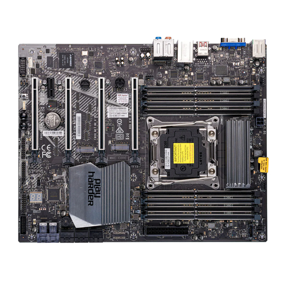
C9X299-PGF-L/C9X299-RPGF-L QUICK REFERENCE GUIDE M.2 Device Installation/Removal Instructions M.2 Device Installation and Removal Instructions M.2 Device Removal M.2 Device Installation... - Page 6 UPERMICR C9X299-PGF-L/C9X299-RPGF-L . 1.00 uiCk eFeRenCe uide Motherboard Layout and Features I/O BACK PANEL J3701 JCOM1 MH15 HD AUDIO KB/Mouse USB 4/5(3.0) LAN1 USB 8/9 (3.1) USB 6/7(3.1) JPB1 MH12 SYS_FAN3 SYS_FAN2 MH14 DIMMB1 DIMMB2 DIMMA1 BAR CODE DIMMA2 IPMI CODE BIOS LICENSE JPW3...
-
Page 7: Jumpers And Connectors
• One Supermicro Motherboard • One I/O Shield • Two SATA Cables • One Driver CD • One Quick Reference Guide Jumpers and Connectors Jumpers Jumper Description Default CLEAR CMOS Clear CMOS Switch Push Button Switch JBT1 Clear CMOS (onboard) -
Page 8: Led Indicators
Notes: 1) For memory optimization, use only DIMM modules that have been validated by Supermicro. For the latest memory updates, please refer to our website at http://www.supermicro.com/products/motherboard. -
Page 9: Cpu Installation
otes • Graphics shown in this quick reference guide are for illustration only. Your components may or may not look exactly the same as drawings shown in this document. • Refer to Chapter 2 in the User's Manual for detailed information on jumpers, connectors, LED indicators, memory support and CPU/motherboard installation instructions. - Page 10 Revision 1.00...
Need help?
Do you have a question about the SuperO C9X299-PGF-L and is the answer not in the manual?
Questions and answers