Table of Contents
Advertisement
Quick Links
Advertisement
Table of Contents

Subscribe to Our Youtube Channel
Related Manuals for Supermicro C9Z490-PG


Summary of Contents for Supermicro C9Z490-PG
- Page 1 C9Z490-PG C9Z490-PGW USER'S MANUAL Revision 1.0...
- Page 2 State of California, USA. The State of California, County of Santa Clara shall be the exclusive venue for the resolution of any such disputes. Supermicro's total liability for all claims will not exceed the price paid for the hardware product.
- Page 3 About This Manual This manual is written for system integrators, IT technicians and knowledgeable end users. It provides information for the installation and use of the C9Z490-PG/-PGW motherboard. About This Motherboard The Supermicro C9Z490-PG/-PGW supports a single 10th Gen Intel® Core i9/i7/i5/i3, Pentium®, and Celeron®...
- Page 4 Super C9Z490-PG/-PGW User's Manual Contacting Supermicro Headquarters Address: Super Micro Computer, Inc. 980 Rock Ave. San Jose, CA 95131 U.S.A. Tel: +1 (408) 503-8000 Fax: +1 (408) 503-8008 Email: marketing@supermicro.com (General Information) support@supermicro.com (Technical Support) Website: www.supermicro.com Europe Address: Super Micro Computer B.V.
-
Page 5: Table Of Contents
Preface Table of Contents Chapter 1 Introduction 1.1 Checklist ..........................8 Quick Reference .......................12 Quick Reference Table ......................13 Motherboard Features .......................15 1.2 Processor and Chipset Overview ..................18 1.3 Special Features ........................18 Recovery from AC Power Loss ..................18 1.4 System Health Monitoring ....................19 Onboard Voltage Monitors ....................19 Fan Status Monitor with Firmware Control ...............19 Environmental Temperature Control .................19... - Page 6 Super C9Z490-PG/-PGW User's Manual 2.4 Memory Support and Installation ..................30 General Guidelines for Optimizing Memory Performance ..........30 DIMM Installation ......................31 DIMM Removal .........................31 2.5 M.2 Installation (optional) ....................32 2.6 Rear I/O Ports ........................34 2.7 Front Control Panel ......................38 2.8 Connectors .........................42 Power Connections ......................42...
- Page 7 Preface Chapter 4 UEFI BIOS 4.1 Introduction .........................65 4.2 EZ Mode ..........................67 4.3 Main ............................68 4.4 Overclocking ........................70 4.5 Advanced ..........................92 4.6 H/W Monitor ........................125 4.7 Boot ..........................127 4.8 Save & Exit ........................129 4.9 BIOS Update ........................131 Appendix A BIOS Codes A.1 BIOS Error POST (Beep) Codes ..................132 A.2 Additional BIOS POST Codes ..................133 Appendix B Software...
-
Page 8: Chapter 1 Introduction
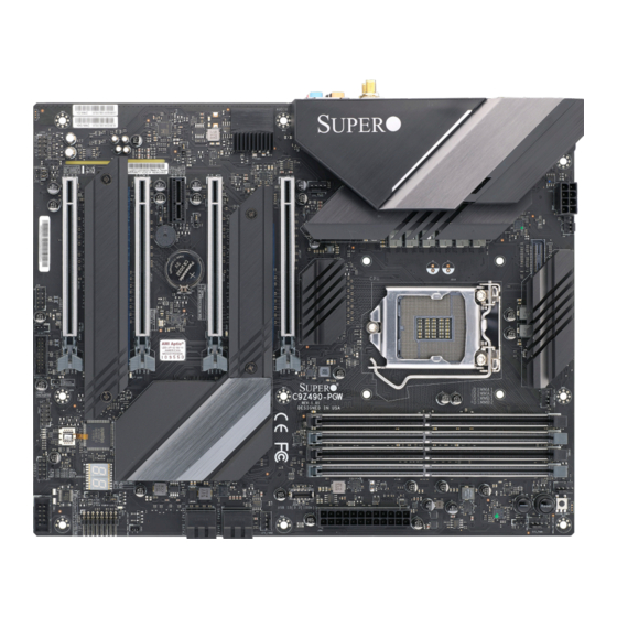
Introduction Congratulations on purchasing your computer motherboard from an industry leader. Supermicro motherboards are designed to provide you with the highest standards in quality and performance. In addition to the motherboard, several important parts that are included in the retail box are listed below. - Page 9 Chapter 1: Introduction Figure 1-1. C9Z490-PGW Motherboard Image Differences between C9Z490-PG and C9Z490-PGW C9Z490-PG C9Z490-PGW PCI-E M.2 E Key for WiFi and Bluetooth Note: All graphics shown in this manual were based upon the latest PCB revision avail- able at the time of publication of the manual. The motherboard you received may or...
- Page 10 Super C9Z490-PG/-PGW User's Manual Figure 1-2. C9Z490-PG Motherboard Layout (not drawn to scale) MAC CODE MAC CODE 10G LAN Controller DP/HDMI USB8 (3.2) USB9 (3.1) HD AUDIO LAN2 (1G) LAN1 (10G) USB6/7 (3.1) USB4/5 (3.0) JRLED1 JI2C2 BAR CODE MH10...
- Page 11 RESET BUTTON BUTTON JLED1 JWD1 USB12 (3.2(10Gb)) CLEAR CMOS I-SATA2 I-SATA0 I-SATA3 I-SATA1 SYS_FAN1 JPW1 SYS_FAN2 Differences between C9Z490-PG and C9Z490-PGW C9Z490-PG C9Z490-PGW PCI-E M.2 E Key for WiFi and Bluetooth Note: Components not documented are for internal testing only.
-
Page 12: Quick Reference
Super C9Z490-PG/-PGW User's Manual Quick Reference Slot 4 Slot 5 HD AUDIO USB8 LAN2 LAN1 USB9 USB6 USB4 HDMI JPAC1 PCIE M.2-M1 WiFi+BT USB7 USB5 SYS_FAN3 JRLED1 JPME2 Slot 1 Slot 3 Slot 7 MAC CODE MAC CODE 10G LAN... -
Page 13: Quick Reference Table
Chapter 1: Introduction Quick Reference Table Jumper Description Default Setting CLEAR CMOS Clear CMOS Switch Push Button Switch JI2C1/JI2C2 SMB to PCI-E Slots Open (Off): Disable JPAC1 Audio Enable/Disable Pins 1-2 (Enable) JPME2 Intel Manufacturing Mode Pins 1-2 (Normal) JWD1 Watch Dog Function Enable Pins 1-2 (RST) POWER BUTTON... - Page 14 Super C9Z490-PG/-PGW User's Manual Connector Description 12V_PUMP_PWR1 12V 4-pin Power Connector for CPU Liquid Cooling Pump AUDIO FP Front Panel Audio Header Onboard Battery COM1 COM1 Header CPU_FAN1 ~ CPU_FAN2 CPU Fan Headers Back Panel DisplayPort HD AUDIO High Definition Audio Ports...
-
Page 15: Motherboard Features
Supports up to 128 of Unbuffered non-ECC UDIMM (288-pin) memory with speeds of up to 2933 MHz in four memory slots. DIMM Size • Up to 128GB at 1.2V Note 1: Memory capacity and frequency is CPU dependent. Note 2: For the latest CPU/memory updates, please refer to our website at http://www.supermicro.com/products/ motherboard. Chipset • Intel PCH Z490 Expansion Slots •... - Page 16 Super C9Z490-PG/-PGW User's Manual Motherboard Features BIOS • 256Mb AMI BIOS SPI Flash BIOS ® • ACPI 6.0, Plug and Play (PnP), BIOS rescue hot-key, riser card auto detection support, and SMBIOS 3.0 or later Power Management • ACPI power management •...
- Page 17 COM1 Header FLASH TPM1.2 Header SPI 128Mb Head Phone Header Differences between C9Z490-PG and C9Z490-PGW C9Z490-PG C9Z490-PGW PCI-E M.2 E Key for WiFi and Bluetooth Note: This is a general block diagram and may not exactly represent the features on your motherboard.
-
Page 18: Processor And Chipset Overview
1.2 Processor and Chipset Overview Built upon the functionality and capability of the 10th Gen Intel Core i9/i7/i5/i3, Pentium, and Celeron series (LAG1200 processor and the Intel PCH Z490 chipset, the C9Z490-PG/-PGW motherboard provides system performance, power efficiency, and feature sets to address the needs of next-generation computer users. -
Page 19: System Health Monitoring
Chapter 1: Introduction 1.4 System Health Monitoring Onboard Voltage Monitors An onboard voltage monitor will scan the voltages of the onboard chipset, memory, CPU, and battery continuously. Once a voltage becomes unstable, a warning is given, or an error message is sent to the screen. The user can adjust the voltage thresholds to define the sensitivity of the voltage monitor. -
Page 20: Acpi Features
It is even more important for processors that have high CPU clock rates where noisy power transmission is present. The C9Z490-PG/-PGW motherboard accommodates a 24-pin ATX power supply. Although most power supplies generally meet the specifications required by the CPU, some are inadequate. -
Page 21: Serial Header
Chapter 1: Introduction 1.7 Serial Header The C9Z490-PG/-PGW motherboard supports one serial communication connection. The COM header can be used for input/output. The UART provides legacy speeds with a baud rate of up to 115.2 Kbps as well as an advanced speed with baud rates of 250 K, 500 K, or 1 Mb/s, which support high-speed serial communication devices. -
Page 22: Chapter 2 Installation
Super C9Z490-PG/-PGW User's Manual Chapter 2 Installation 2.1 Static-Sensitive Devices Electrostatic Discharge (ESD) can damage electronic com ponents. To avoid damaging your system board, it is important to handle it very carefully. The following measures are generally sufficient to protect your equipment from ESD. -
Page 23: Processor And Heatsink Installation
Thermal grease is pre-applied on a new heatsink. No additional thermal grease is needed. • Refer to the Supermicro website for updates on processor support. • All graphics in this manual are for illustrations only. Your components may look different. - Page 24 Super C9Z490-PG/-PGW User's Manual 2. Gently lift the load lever to open the load plate. Remove the plastic cap. 3. Use your thumb and your index finger to hold the CPU at the North center edge and the South center edge of the CPU.
- Page 25 Chapter 2: Installation 5. Do not rub the CPU against the surface or against any pins of the socket to avoid damaging the CPU or the socket.) 6. With the CPU inside the socket, inspect the four corners of the CPU to make sure that the CPU is properly installed.
-
Page 26: Installing An Active Cpu Heatsink With Fan
Super C9Z490-PG/-PGW User's Manual Installing an Active CPU Heatsink with Fan 1. Apply the proper amount of thermal grease to the heatsink. 2. Place the heatsink on top of the CPU so that the four mounting holes on the heatsink are aligned with those on the retention mechanism. -
Page 27: Removing An Active Cpu Heatsink With Fan
Chapter 2: Installation Removing an Active CPU Heatsink with Fan Warning: We do not recommend that the CPU or heatsink be removed. However, if you do need to remove the heatsink, please follow the instruction below to uninstall the heatsink to avoid damaging the CPU or other components. -
Page 28: Motherboard Installation
Super C9Z490-PG/-PGW User's Manual 2.3 Motherboard Installation All motherboards have standard mounting holes to fit different types of chassis. Make sure that the locations of all the mounting holes for both the motherboard and the chassis match. Although a chassis may have both plastic and metal mounting fasteners, metal ones are highly recommended because they ground the motherboard to the chassis. -
Page 29: Installing The Motherboard
Chapter 2: Installation Installing the Motherboard 1. Install the I/O shield into the back of the chassis, if applicable. 2. Locate the mounting holes on the motherboard. Refer to the previous page for the location. 3. Locate the matching mounting holes on the chassis. Align the mounting holes on the motherboard against the mounting holes on the chassis. -
Page 30: Memory Support And Installation
Super C9Z490-PG/-PGW User's Manual 2.4 Memory Support and Installation Note: Check the Supermicro website for recommended memory modules. Important: Exercise extreme care when installing or removing DIMM modules to pre- vent any possible damage. General Guidelines for Optimizing Memory Performance •... -
Page 31: Dimm Installation
Chapter 2: Installation DIMM Installation MAC CODE MAC CODE 10G LAN Controller DP/HDMI 1. Insert DIMM modules in the following USB8 (3.2(10Gb)) USB9 (3.2(20Gb)) HD AUDIO LAN2 LAN1 USB6/7 (3.2(10Gb)) USB4/5 (3.2(5Gb)) JRLED1 JI2C2 BAR CODE WiFi+BT MH10 LAN Controller rder: DIMMA2, DIMMB2, then DIMMA1, SYS_FAN3 LED18... -
Page 32: Installation (Optional)
Super C9Z490-PG/-PGW User's Manual 2.5 M.2 Installation (optional) Two M.2 M key sockets are supported by the C9Z490-PG/-PGW. M.2 devices are used for solid state storage and internal expansion. Follow the steps below in order to install an M.2 device. - Page 33 Chapter 2: Installation 4. Remove the M.2 heatsink thermal pad cover. 5. Replace the M.2 heatsink and the retaining screws. Tighten the screws to secure the heatsink into place. Notes: 1. DO NOT install the bounded M.2 heatsink (refer to step 4 and 5) if the M.2 device has a heatsink installed.
-
Page 34: Rear I/O Ports
Super C9Z490-PG/-PGW User's Manual 2.6 Rear I/O Ports Refer to Figure 2-1 below for the locations and descriptions of the various I/O ports on the rear of the motherboard. MAC CODE MAC CODE 10G LAN Controller DP/HDMI USB8 (3.2(10Gb)) USB9 (3.2(20Gb)) - Page 35 Chapter 2: Installation Universal Serial Bus (USB) Ports Two USB 3.2 Gen 1 Type A ports (USB4/5), two USB 3.2 Gen 2 Type A ports (USB6/8), one USB 3.2 Gen 2 Type C port (USB7), and one USB 3.2 Gen 2x2 Type C port (USB9) are located on the I/O back panel.
- Page 36 Super C9Z490-PG/-PGW User's Manual Back Panel High Definition Audio (HD Audio) This motherboard features a 7.1+2 Channel High Definition Audio (HDA) codec that provides 10 DAC channels. The HD Audio connections simultaneously supports multiple-streaming 7.1 sound playback with 2 channels of independent stereo output through the front panel stereo out for front, rear, center and subwoofer speakers.
- Page 37 Chapter 2: Installation DisplayPort Port DisplayPort, developed by the VESA consortium, delivers digital display at a fast refresh rate. It can connect to virtually any display device using a DisplayPort adapter for devices, such as VGA, DVI, and HDMI. HDMI Port One HDMI 2.0a (High-Definition Multimedia Interface) port is located on the I/O back panel.
-
Page 38: Front Control Panel
JF1 contains header pins for various buttons and indicators that are normally located on a control panel at the front of the chassis. These connectors are designed specifically for use with Supermicro chassis. Refer to the figure below for the descriptions of the front control panel buttons and LED indicators. - Page 39 Chapter 2: Installation Power LED The Power LED connection is located on pins 15 and 16 of JF1. Refer to the table below for pin definitions. Power LED Pin Definitions (JF1) Pin# Definition Power LED HDD LED The HDD LED connection is located on pins 13 and 14 of JF1. Attach a cable here to indicate the status of HDD-related activities, including IDE and SATA activities.
- Page 40 Super C9Z490-PG/-PGW User's Manual NIC1/NIC2 (LAN1/LAN2) LED The NIC (Network Interface Controller) LED connection for LAN1/LAN2 is located on pins 9/11 and 10/12 of JF1. Attach an LED indicator to this header to display network activity. Refer to the table below for pin definitions.
- Page 41 Chapter 2: Installation Reset Button The Reset Button connection is located on pins 3 and 4 of JF1. Attach it to a hardware reset switch on the computer case to reset the system. Refer to the table below for pin definitions. Reset Button Pin Definitions (JF1) Pin#...
-
Page 42: Connectors
Super C9Z490-PG/-PGW User's Manual 2.8 Connectors This section provides brief descriptions and pinout definitions for onboard headers and connectors. Be sure to use the correct cable for each header or connector. Power Connections ATX Power Supply Connector The 24-pin power supply connector (JPW1) meets the ATX SSI EPS 12V specification. You must also connect the 8-pin (JPW2) processor power connector to the power supply. - Page 43 Chapter 2: Installation 8-Pin Power Connector JPW2 is an 8-pin 12V DC power input for the CPU that must be connected to the power supply. Refer to the table below for pin definitions. 8-pin Power Pin Definitions Pin# Definition 1 - 4 Ground 5 - 8 +12V...
-
Page 44: Headers
Super C9Z490-PG/-PGW User's Manual Headers Fan Headers There are five 4-pin fan headers (CPU_FAN1 ~ CPU_FAN2, SYS_FAN1 ~ SYS_FAN3) on the motherboard. Although Pins 1-3 of the system fan headers are backwards compatible with the traditional 3-pin fans, the 4-pin fans are recommended to take advantage of the fan speed control. - Page 45 Chapter 2: Installation Chassis Intrusion Header A Chassis Intrusion header is located at JL1 on the motherboard. Attach the appropriate cable from the chassis to inform you of a chassis intrusion when the chassis is opened. Chassis Intrusion Header Pin Definitions Pin# Definition Intrusion Input...
- Page 46 Super C9Z490-PG/-PGW User's Manual Power LED Header An onboard Power LED header is located at JLED1. This Power LED header is connected to the Front Control Panel located at JF1 to indicate the status of system power. Refer to the table below for pin definitions.
- Page 47 Chapter 2: Installation DOM PWR Connector The Disk-On-Module (DOM) power connector, located at JSD1, provides 5V power to a solid state DOM storage device connected to one of the SATA ports. Refer to the table below for pin definitions. DOM PWR Connector Pin Definitions Pin# Definition...
- Page 48 Super C9Z490-PG/-PGW User's Manual M.2 Sockets M.2 sockets are designed for devices such as memory cards, wireless adapters, etc. These devices must conform to the PCI-E M.2 specifications (formerly known as NGFF). Note: PCIE M.2-M1 and PCIE M.2-M2 support RAID 0 and RAID 1.
- Page 49 Chapter 2: Installation Front Panel Audio Header A 10-pin Audio header at AUDIO FP is supported on the motherboard. This header allows you to connect the motherboard to a front panel audio control panel, if needed. Connect an audio cable to the audio header to use this feature (not supplied). Refer to the table below for pin definitions.
- Page 50 Super C9Z490-PG/-PGW User's Manual Serial (COM) Header There is one serial (COM port) header on the motherboard. COM1 is located next to the header. Refer to the table below for pin definitions. Serial (COM) Header Pin Definitions Pin# Definition Pin#...
-
Page 51: Jumper Settings
Chapter 2: Installation 2.9 Jumper Settings How Jumpers Work To modify the operation of the motherboard, jumpers can be used to choose between optional settings. Jumpers create shorts between two pins to change the function of the connector. Pin 1 is identified with a square solder pad on the printed circuit board. Refer to the diagram below for an example of jumping pins 1 and 2. - Page 52 Super C9Z490-PG/-PGW User's Manual Clear CMOS/SW1 Button Clear CMOS Button is used to clear the saved system setup configuration stored in the CMOS chip. All the settings will be erased and restored to the factory defaults after pressing this button. In this motherboard, there are two buttons which built-in this function. One is the...
- Page 53 Chapter 2: Installation Audio Enable/Disable Jumper JPAC1 allows you to enable or disable the onboard audio support. The default position is on pins 1 and 2 to enable onboard audio connections. Refer to the table below for jumper settings. Audio Enable/Disable Jumpers Settings Jumper Setting Definition...
- Page 54 Super C9Z490-PG/-PGW User's Manual PCI Slot SMB Jumpers Use Jumpers JI2C1 and JI2C2 to enable PCI SMB (System Management Bus) support to improve system management for the PCI slots. Refer to the table below for jumper settings. PCI Slot SMB...
-
Page 55: Led Indicators
Chapter 2: Installation 2.10 LED Indicators LAN LEDs Two LAN ports are located on the I/O back panel of the motherboard. Link Activity This Ethernet LAN port has two LEDs (Light Emitting Diode). The yellow LED indicates activity, while the Link LED may be green, amber, or off to indicate the speed of the connections. - Page 56 Super C9Z490-PG/-PGW User's Manual JSTBY1 M.2 LED Two M.2 LEDs are provided and indicated the status of connected M.2 devices. When a M.2 LED is blinking, it's corresponding M.2 device function normally. The LED2 is located next to the M.2 M2 socket and LED3 is next to the M.2 M1 socket on the motherboard. Refer to the LED3 table below for more information.
- Page 57 Chapter 2: Installation POST (Power-On Self-Test) LEDs Multiple LEDs are built-in and used to display the status of system POST (Power-On Self- Test). These LEDs are located next to the JTPM1 header on the motherboard. Refer to the tables below for more information. CPU LED State DIMM LED State LED Color...
-
Page 58: Chapter 3 Troubleshooting
Super C9Z490-PG/-PGW User's Manual Chapter 3 Troubleshooting 3.1 Troubleshooting Procedures Use the following procedures to troubleshoot your system. If you have followed all of the procedures below and still need assistance, refer to the ‘Technical Support Procedures’ and/ or ‘Returning Merchandise for Service’ section(s) in this chapter. Always disconnect the AC power cord before adding, changing or installing any non hot-swap hardware components. -
Page 59: No Video
Chapter 3: Troubleshooting No Video 1. If the power is on, but you have no video, remove all add-on cards and cables. 2. Use the speaker to determine if any beep codes are present. Refer to Appendix A for details on beep codes. 3. -
Page 60: Losing The System's Setup Configuration
Super C9Z490-PG/-PGW User's Manual Losing the System's Setup Configuration 1. Make sure that you are using a high-quality power supply. A poor-quality power supply may cause the system to lose the CMOS setup information. Refer to Section 1.6 Power Supply in Chapter 1 for details on recommended power supplies. -
Page 61: Technical Support Procedures
Before contacting Technical Support, please take the following steps. Also, please note that as a motherboard manufacturer, Supermicro also sells motherboards through its channels, so it is best to first check with your distributor or reseller for troubleshooting services. They should know of any possible problems with the specific system configuration that was sold to you. -
Page 62: Frequently Asked Questions
Note: The SPI BIOS chip used on this motherboard cannot be removed. Send your moth- erboard back to our RMA Department at Supermicro for repair. For BIOS Recovery instruc- tions, please refer to the AMI BIOS Recovery Instructions posted at http://www.supermi-... -
Page 63: Battery Removal And Installation
Chapter 3: Troubleshooting 3.4 Battery Removal and Installation Battery Removal To remove the onboard battery, follow the steps below: 1. Power off your system and unplug your power cable. 2. Locate the onboard battery as shown below. 3. Using a tool such as a pen or a small screwdriver, push the battery lock outwards to unlock it. -
Page 64: Returning Merchandise For Service
Super C9Z490-PG/-PGW User's Manual 3.5 Returning Merchandise for Service A receipt or copy of your invoice marked with the date of purchase is required before any warranty service will be rendered. You can obtain service by calling your vendor for a Returned Merchandise Authorization (RMA) number. -
Page 65: Chapter 4 Uefi Bios
Chapter 4: UEFI BIOS Chapter 4 UEFI BIOS 4.1 Introduction This chapter describes the AMIBIOS™ Setup utility for the motherboard. The BIOS is stored on a chip and can be easily upgraded using a flash program. Note: Due to periodic changes to the BIOS, some settings may have been added or deleted and might not yet be recorded in this manual. - Page 66 Super C9Z490-PG/-PGW User's Manual The AMI BIOS GUI Setup Utility uses a mouse pointer navigation system similar to standard graphical user interfaces. Hover and click an icon to select a section, click a down arrow to select from an options list.
-
Page 67: Ez Mode
Chapter 4: UEFI BIOS 4.2 EZ Mode While in EZ Mode, the following information will be displayed: • BIOS Version - The current BIOS version • CPU Information - The model, speed, and voltage of installed CPU • Memory Frequency - The frequency of installed memory •... -
Page 68: Main
Super C9Z490-PG/-PGW User's Manual 4.3 Main BIOS Information The following items will be displayed: • BIOS Version - This feature displays the version of the BIOS ROM used in the system. • Build Date - This feature displays the date of when the BIOS ROM version used in the system was built. - Page 69 Chapter 4: UEFI BIOS Processor Information The following items will be displayed: • Brand String - This feature displays the brand, model name, model number of the CPU, and its rated clock speed. • Frequency - This feature displays the detected CPU speed •...
-
Page 70: Overclocking
Super C9Z490-PG/-PGW User's Manual 4.4 Overclocking CPU Profile This feature allows for preset CPU overclocking profiles to be selected. The options are Stable, Default, and Performance. BCLK Clock Frequency (1/100MHz) Enter a value for the BCLK frequency. The default is Auto. - Page 71 Chapter 4: UEFI BIOS Advanced CPU OC Setting Processor BCLK Aware Adaptive Voltage This feature enables BCLK Aware Adaptive Voltage, which helps avoid high voltage overrides by forcing pcode to be aware of the BCLK frequency when making calculations. The options are Disabled and Enabled. Core Max OC Ratio This feature controls the general maximum overclocking ratio for the CPU cores and Ring.
- Page 72 Super C9Z490-PG/-PGW User's Manual Power Limit 1 This feature displays the value of Power Limit 1. Power Limit 2 This feature displays the value of Power Limit 2. Custom Settings Nominal ConfigTDP Nominal This feature displays the value of ConfigTDP Nominal.
- Page 73 Chapter 4: UEFI BIOS Power Limit 2 Use this feature to set the power limit 2. Use the number keys on your keyboard to enter the value. The default setting is 0. Power Limit 1 Time Window This feature determines how long the time window over which the TDP value is main- tained.
- Page 74 Super C9Z490-PG/-PGW User's Manual Intel(R) SpeedStep(tm) Intel SpeedStep Technology allows the system to automatically adjust processor volt- age and core frequency in an effort to reduce power consumption and heat dissipation. Please refer to Intel’s website for detailed information. The options are Disabled and Enabled.
- Page 75 Chapter 4: UEFI BIOS Min Ring Ratio Limit Enter a numeric value for the minimum ratio limit for CPU Ring. The default is Auto. Max Ring Ratio Limit Enter a numeric value for the maximum ratio limit for CPU Ring. The default is Auto. CPU VR Settings CPU VR Settings VR Power Delivery Design...
- Page 76 Super C9Z490-PG/-PGW User's Manual IA VR Domain / GT VR Domain / SA VR Domain / VccIn VR Domain Disable Fast PKG C State Ramp for IA Domain This feature disables fast package C-state ramping in a specific domain. If set to FALSE, the selected domain will continue to fast ramp.
- Page 77 Chapter 4: UEFI BIOS IMON Offset Enter a value for IMON Offset. The range is 0-63999. The default is 0. IMON Prefix Use this feature to set the prefix value as a positive (+) or a negative (-). The options are “+” and “-”. VR Current Limit Enter a value for the voltage regulator current limit, with each whole number equat- ing to 1/4A (i.e., 400 = 100A).
- Page 78 Super C9Z490-PG/-PGW User's Manual PS Current Threshold1 Enter a value for PS Current Threshold1. The range is 0-512. The default is 80. PS Current Threshold2 Enter a value for PS Current Threshold2. The range is 0-512. The default is 20.
- Page 79 Chapter 4: UEFI BIOS Thermal Voltage Boost (TVB) TVB Ratio Clipping This feature enables CPU core frequency reduction for processors that implement Intel Thermal Velocity Boost (TVB). For overclocking, this feature must be Disabled. TVB Voltage Optimizations This feature enables thermal base voltage optimizations for processors that implement Intel Thermal Velocity Boost (TVB).
- Page 80 Super C9Z490-PG/-PGW User's Manual Intel(R) Turbo Boost Max Technology 3.0 Select Enabled to use the Intel Turbo Boost Max Technology. The options are Disabled and Enabled. C States C-State architecture, a processor power management platform developed by Intel, can further reduce power consumption from the basic C1 (Halt State) state that blocks clock cycles to the CPU.
- Page 81 Chapter 4: UEFI BIOS Max Ring Ratio Limit Enter a numeric value for the maximum ratio limit for CPU Ring. The default is Auto. CPU VR Settings CPU VR Settings VR Power Delivery Design This feature is intended for motherboard validation purposes. The specifies the CFL-S board design for VR settings override values.
- Page 82 Super C9Z490-PG/-PGW User's Manual Slow slew Rate for IA Domain This feature controls the slow slew rate for a specific domain. The options are Fast/2, Fast/4, Fast/8, and Fast/16. Core/IA VR Settings Core/IA VR Settings VR Config Enable This feature enables VR Config. The options are Disabled and Enabled.
- Page 83 Chapter 4: UEFI BIOS VR Current Limit Enter a value for the voltage regulator current limit, with each whole number equat- ing to 1/4A (i.e., 400 = 100A). Enter 0 for Auto. VR Voltage Limit Enter a value (in mV) for the voltage regulator voltage limit. The range is 0-7999. Enter 0 for Auto.
- Page 84 Super C9Z490-PG/-PGW User's Manual PS Current Threshold3 Enter a value for PS Current Threshold3. The range is 0-512. The default is 4. PS3 Enable This feature enables PS3. The options are Disabled and Enabled. PS4 Enable This feature enables PS4. The options are Disabled and Enabled.
- Page 85 Chapter 4: UEFI BIOS Intersil VR Command This feature enables Intersil VR Command to fix VR C-state issues. The options are Disabled, Send for IA/GT rails, and Send for IA/GT/SA rails. GT GT Domain GT OverClocking Frequency Enter a value for the overclocked RP0 frequency (in multiples of 50 MHz) in the GT domain.
- Page 86 Super C9Z490-PG/-PGW User's Manual GTU Voltage Offset Enter a value for the offset voltage (in mV) that will be applied to the GT domain. The default is 0. Offset Prefix Use this feature to set the prefix value as a positive (+) or a negative (-). The options are “+”...
- Page 87 Chapter 4: UEFI BIOS tRCD/tRP This feature configures the RAS to CAS delay time. Enter a numeric value between 1-63. The default is 15. tRAS This feature configures the Ras Active Time. Enter a numeric value between 1-64. The default is 36. tCWL This feature configures the Minimum CAS Write Latency Time.
- Page 88 Super C9Z490-PG/-PGW User's Manual NMode This feature configures the System Command Rate. Enter a numeric value between 0-2. The default is Auto. tRRD_sg tRRD_dg tRDRD_sg tRDRD_dg tRDRD_dr tRDRD_dd tRDWR_sg tRDWR_dg tRDWR_dr tRDWR_dd tWRRD_sg tWRRD_dg tWRRD_dr tWRRD_dd tWRWR_sg tWRWR_dg tWRWR_dr tWRWR_dd...
- Page 89 Chapter 4: UEFI BIOS RcompTarget[RdOdt] RcompTarget[WrDS] RcompTarget[WrDSCmd] RcompTarget[WrDSCtl] RcompTarget[WrDSClk] DllBwEn[0] DllBwEn[1] DllBwEn[2] DllBwEn[3] Enter a desired numeric value above for each feature. The default of these features is 0. Load line Calibration This feature controls the load line calibration. The options are Disabled, Level 1, Level 2, Level 3, Level 4, Level 5, Level 6, Level 7, and Auto.
- Page 90 Super C9Z490-PG/-PGW User's Manual Memory Voltage Enter a numeric value for the memory voltage override. The default is Auto. PCH Voltage Enter a numeric value for the PCH voltage override. The default is Auto. CPU_IO Voltage Enter a numeric value for the CPU IO voltage override. The default is Auto.
- Page 91 Chapter 4: UEFI BIOS Voltage PLL Trim Controls Voltage PLL Trim Controls Core PLL Voltage Offset GT PLL Voltage Offset Ring PLL Voltage Offset System Agent PLL Voltage Offset Memory Controller PLL Voltage Offset Enter a desired numeric value above for each feature. The range is 0-63 and the default is 0.
-
Page 92: Advanced
Super C9Z490-PG/-PGW User's Manual 4.5 Advanced Setup Mode This feature sets the default mode to start in after entering BIOS. The options are EZ Mode and Advanced Mode. Boot Feature Fast Boot This feature enables the system to boot with a minimal set of required devices to launch. - Page 93 Chapter 4: UEFI BIOS Re-try Boot If this feature is enabled, the BIOS will automatically reboot the system from a specified boot device after its initial boot failure. The options are Disabled, Legacy Boot, and EFI Boot. Power Configuration Watch Dog Function If enabled, the Watch Dog Timer will allow the system to reset or generate NMI based on jumper settings when it is expired for more than five minutes.
- Page 94 Super C9Z490-PG/-PGW User's Manual CPU Configuration CPU Configuration The following CPU information will be displayed: • Brand String - the brand and speed of installed CPU • Frequency - the frequency of installed CPU • ID - the unique CPU ID •...
- Page 95 Chapter 4: UEFI BIOS *If this feature of is set to Enabled, the following features will become available for configuration: Select Owner EPOCH Input Type There are three Owner EPOCH modes (each EPOCH is 64 bit). The options are No Change in Owner EPOCHs, Change to New Random Owner EPOCH, and Manual User Defined Owner EPOCHs.
- Page 96 Super C9Z490-PG/-PGW User's Manual Hardware Prefetcher If set to Enabled, the hardware prefetcher will prefetch streams of data and instructions from the main memory to the L2 cache to improve CPU performance. The options are Disabled and Enabled. Adjacent Cache Line Prefetch Select Enabled for the CPU to prefetch both cache lines for 128 bytes as comprised.
- Page 97 Chapter 4: UEFI BIOS Graphics Configuration Graphics Configuration Note: Only the feature of Primary Display is available for configuring if the installed CPU doesn’t have integrated graphics. Graphics Turbo IMON Current Enter a value for the graphics turbo IMON current. The range is 14-31. The default is 31. Skip Scanning of External Gfx Card This feature disables scanning for external graphics cards.
- Page 98 Super C9Z490-PG/-PGW User's Manual PAVP Enable This feature enables PAVP support. The options are Disabled and Enabled. Cdynmax Clamping Enable This feature enables Cdynmax Clamping. The options are Disabled and Enabled. Graphics Clock Frequency This feature controls the graphics clock frequency. Select the highest clock frequency supported by the platform.
- Page 99 Chapter 4: UEFI BIOS HTTP BOOT Configuration HTTP BOOT Configuration Http Boot One Time This feature enables HTTP Boot, which is a client-server communication based application for system deployment and configuration over a network. The options are Disabled and Enabled. Input the description Enter a name for Http boot option.
- Page 100 Super C9Z490-PG/-PGW User's Manual Max TOLUD (Top of Low Usable DRAM) This feature sets the maximum TOLUD value, which specifies the "Top of Low Usable DRAM" memory space to be used by internal graphics devices, GTT Stolen Memory, and TSEG, respectively, if these devices are enabled. The options are Dynamic, 1 GB, 1.25 GB, 1.5 GB, 1.75 GB, 2 GB, 2.25 GB, 2.5 GB, 2.75 GB, 3 GB, 3.25 GB, and 3.5 GB.
- Page 101 Chapter 4: UEFI BIOS Serial Port This feature will Enable or Disable Serial Port 1 (COM1). Check the box to enable Serial Port 1. The default is Checked. Device Settings - IO=3F8h; IRQ=4; Change Settings This feature configures the IRQ setting for Serial Port 1 (COM1). The options for Se- rial Port 1 are Auto, "IO=3F8h;...
- Page 102 Super C9Z490-PG/-PGW User's Manual • UEFI Driver • Adapter PBA • Chip Type • PCI Device ID • PCI Adress • Link Status • MAC Address MAC: XXXXXXXXXXXX-IPv4 Network Configuration Configured This feature indicates whether a network address configured successfully or not. The default is Unchecked.
- Page 103 Chapter 4: UEFI BIOS MAC: XXXXXXXXXXXX-HTTP Boot Configuration Note: This submenu becomes configurable when the IPv4 HTTP Support IPv6 HTTP Support is set to Enabled. Input the description This feature is an input field that, when the HTTP boot option is created, can be used to enter text to describe or identify the HTTP connection.
- Page 104 Super C9Z490-PG/-PGW User's Manual Policy Use this feature to set the Policy. The options are Automatic and Manual. *If this feature is set to Manual, the following features will become available for configuration: Advanced Configuration New IPv6 Address - Enter a new IPv6 address...
- Page 105 Chapter 4: UEFI BIOS PCH-IO Configuration PCH-IO Configuration HD Audio This feature controls the detection of HD Audio devices. The options are Disabled and Enabled. Wake on LAN Enable This feature enables integrated LAN to wake the system. The options are Disabled and Enabled.
- Page 106 Super C9Z490-PG/-PGW User's Manual PCIe/PCI/PnP Configuration PCIe/PCI/PnP Configuration CPU SLOT1 PCI-E 3.0 X8 (IN X16) OPROM CPU SLOT3 PCI-E 3.0 X16 OPROM PCH SLOT4 PCI-E 3.0 X1 OPROM CPU SLOT5 PCI-E 3.0 X8 (IN X16) OPROM CPU SLOT7 PCI-E 3.0 X16 OPROM PCIE M.2-M1 OPROM...
- Page 107 Chapter 4: UEFI BIOS Option ROM execution Video This feature controls which option ROM to execute for the Video device. The options are Do Not Launch, Legacy, and EFI. Note: These options are subject to change depending on the feature of Boot Mode Select.
- Page 108 Super C9Z490-PG/-PGW User's Manual Ipv6 HTTP Support Use this feature to enable IPv6 HTTP boot support. The options are Disabled and Enabled. PXE boot wait time Enter a value for the wait time (in seconds) to press the <ESC> key to abort the PXE boot.
- Page 109 Chapter 4: UEFI BIOS C-State Un-demotion When this feature is enabled, the CPU will conditionally un-demote from demoted C3 or C1. The options are Disabled, C1, C3, and C1 and C3. Package C-State Demotion This feature enables the Package C-State demotion. The options are Disabled and Enabled.
- Page 110 Super C9Z490-PG/-PGW User's Manual Disable Turbo GT frequency This feature disables Turbo GT frequency. If set to Enabled, Turbo GT frequency be- comes disabled. If set to Disabled, GT frequency limiters will be removed.The options are Disabled and Enabled. SATA And RST Configuration...
- Page 111 Chapter 4: UEFI BIOS Aggressive LPM Support This feature enables the PCH to aggressively enter link power state. The options are Disabled and Enabled. Serial ATA Port0~3 Hot Plug This feature designates the port specified for hot plugging. Set the setting to Enabled for hot-plugging support, which will allow the user to replace a SATA disk drive without shutting down the system.
- Page 112 Super C9Z490-PG/-PGW User's Manual *If the feature of Secure Boot Mode is set to Custom, the features below will become available for configuration: Enter Audit Mode This submenu can only be used if current System Mode is set to User (refer to Exit Deployed Mode).
- Page 113 Chapter 4: UEFI BIOS Restore DB Defaults Select Yes to restore the DB defaults or select No to cancel. Secure Boot Variable / Size / Keys / Key Source Platform Key (PK) This feature allows the user to configure the settings of the platform keys. Details Review details on current settings of the platform keys.
- Page 114 Super C9Z490-PG/-PGW User's Manual Authorized Signatures Details Review details on current settings of Authorized Signatures. Export This feature allows the user to export Authorized Signatures to an available file system. Update Select Yes to load the factory default DB. Select No to load the DB from a external file.
- Page 115 Chapter 4: UEFI BIOS Authorized TimeStamps Details Review details on current settings of the Authorized TimeStamps. Export This feature allows the user to export Authorized TimeStamps to an available file system. Update Select Yes to load the DBT from the manufacturer's defaults. Select No to load the DBT from a file.
- Page 116 Super C9Z490-PG/-PGW User's Manual Security Security Hard Drive Security Frozen Use this feature to enable BIOS security frozen command to SATA and NVME devices. The options are Disabled and Enabled. Password Check Select Setup for the system to check for a password at Setup. Select Always for the system to check for a password at bootup or upon entering the BIOS Setup utility.
- Page 117 Chapter 4: UEFI BIOS Serial Port Console Redirection Serial Port Console Configuration COM1 COM1 Console Redirection Check the box to enable console redirection support for a serial port specified by the user. The options are Unchecked and Checked. * If the feature above is set to Checked, the following features will become available for configuration: COM1 Console Redirection Settings COM1 Console Redirection Settings...
- Page 118 Super C9Z490-PG/-PGW User's Manual COM1 Parity A parity bit can be sent along with regular data bits to detect data transmission errors. Select Even if the parity bit is set to 0, and the number of 1's in data bits is even. Select Odd if the parity bit is set to 0, and the number of 1's in data bits is odd.
- Page 119 Chapter 4: UEFI BIOS COM1 Redirection After BIOS POST Use this feature to enable or disable legacy console redirection after BIOS POST. When set to Bootloader, legacy console redirection is disabled before booting the OS. When set to Always Enable, legacy console redirection remains enabled when booting the OS. The options are Always Enable and Bootloader.
- Page 120 Super C9Z490-PG/-PGW User's Manual The setting for each of these features is displayed: • Data Bits • Parity • Stop Bits System Agent (SA) Configuration System Agent (SA) Configuration The following information will be displayed: • SA PCIe Code Version •...
- Page 121 Chapter 4: UEFI BIOS VT-d This feature enables VT-d capability. The options are Disabled and Enabled. GNA Device (B0:D8:F0) This feature enables the SA GNA device. The options are Disabled and Enabled. X2APIC Opt Out This feature enables X2APIC Opt Out. The options are Disabled and Enabled. Trusted Computing Note: 1.
- Page 122 Super C9Z490-PG/-PGW User's Manual Pending operation This feature schedules an operation for the security device. Changing this setting will reboot the system. The options are None and TPM Clear. Platform Hierarchy This feature enables Platform Hierarchy. The options are Disabled and Enabled.
- Page 123 Chapter 4: UEFI BIOS XHCI Hand-off This feature is a workaround solution for operating systems that do not support XHCI (Extensible Host Controller Interface) hand-off. The XHCI ownership change should be claimed by the XHCI driver. The options are Disabled and Enabled. USB Mass Storage Driver Support This feature enables USB mass storage driver support.
- Page 124 Super C9Z490-PG/-PGW User's Manual • Security Locked • Security Frozen • User Pwd Status • Admin Pwd Status Set Admin Password Press <Enter> to create a new admin password. Set User Password Press <Enter> to create a new user password.
-
Page 125: H/W Monitor
Chapter 4: UEFI BIOS 4.6 H/W Monitor System Temperature The following items will be displayed: • CPU Temperature - the CPU temperature detected by PECI • System Temperature - the system internal temperature • Peripheral Temperature - the detected peripheral device temperature •... - Page 126 Super C9Z490-PG/-PGW User's Manual • VCPU • VCPU_STPLL • VCC3_ALW • VBAT • 3.3V_DL Fan Control Fan Control Setting Fan Speed Control Mode This feature allows the user to decide how the system controls the speeds of the onboard fans. The CPU temperature and the fan speed are correlative. When the CPU on-die temperature increases, the fan speed will also increase for effective system cooling.
-
Page 127: Boot
Chapter 4: UEFI BIOS 4.7 Boot Boot mode select Use this feature to select the type of device to be used for system boot. The options are Legacy, UEFI, and Dual. Fixed Boot order Priorities This feature prioritizes the order of bootable devices from which the system will boot. Choose an entry from top to bottom to select devices. - Page 128 Super C9Z490-PG/-PGW User's Manual Add New Boot Option Add New Boot Option Add New Boot Option Use this item to specify the name for the new boot option. Path for Boot Option Use this feature to enter the path for the new boot option in the format fsx:\path\filename.efi.
-
Page 129: Save & Exit
Chapter 4: UEFI BIOS 4.8 Save & Exit Save Options Save Changes and Exit Use this feature to save the changes you have made and reboot the system. Discard Changes and Exit Use this feature to exit the system without saving any changes and reboot the system. Discard Changes Use this feature to discard the changes you have made and remain in setup mode. - Page 130 Super C9Z490-PG/-PGW User's Manual Load Profile 1/2 This feature will load a previously saved overclocking profile from either Profile 1 or Profile 2 location. Click OK to load the profile, otherwise, click Cancel. Boot override This feature allows the user to override the Boot priorities sequence in the Boot menu, and immediately boot the system with a device specified by the user instead of the one specified in the boot list.
-
Page 131: Bios Update
Chapter 4: UEFI BIOS 4.9 BIOS Update The following items will be displayed: • BIOS Version • BIOS Tag • Date • Time Start Update Use this utility to prepare BIOS Update with ME. 1. Click "Start Update" enter the SuperFlash utility. 2. -
Page 132: Appendix A Bios Codes
Super C9Z490-PG/-PGW User's Manual Appendix A BIOS Codes A.1 BIOS Error POST (Beep) Codes During the POST (Power-On Self-Test) routines, which are performed each time the system is powered on, errors may occur. Non-fatal errors are those which, in most cases, allow the system to continue the boot-up process. -
Page 133: Additional Bios Post Codes
When BIOS performs the Power On Self Test, it writes checkpoint codes to I/O port 0080h. If the computer cannot complete the boot process, a diagnostic card can be attached to the computer to read I/O port 0080h (Supermicro p/n AOC-LPC80-20). For information on AMI updates, please refer to http://www.ami.com/products/. -
Page 134: Appendix B Software
Appendix B Software B.1 Driver Installation The Supermicro website that contains drivers and utilities for your system is at https://www. supermicro.com/wftp/driver. Some of these must be installed, such as the chipset driver. After accessing the website, go into the CDR_Images (in the parent directory of the above link) and locate the ISO file for your motherboard. -
Page 135: Superdoctor ® 5
B.2 SuperDoctor ® The Supermicro SuperDoctor 5 is a program that functions in a command-line or web-based interface for Windows and Linux operating systems. The program monitors such system health information as CPU temperature, system voltages, system power consumption, fan speed, and provides alerts via email or Simple Network Management Protocol (SNMP). -
Page 136: Appendix C Standardized Warning Statements
The following statements are industry standard warnings, provided to warn the user of situations which have the potential for bodily injury. Should you have questions or experience difficulty, contact Supermicro's Technical Support department for assistance. Only certified technicians should attempt to install or configure components. - Page 137 Appendix C: Standardized Warning Statements Attention Danger d'explosion si la pile n'est pas remplacée correctement. Ne la remplacer que par une pile de type semblable ou équivalent, recommandée par le fabricant. Jeter les piles usagées conformément aux instructions du fabricant. ¡Advertencia! Existe peligro de explosión si la batería se reemplaza de manera incorrecta.
- Page 138 Super C9Z490-PG/-PGW User's Manual Product Disposal Warning! Ultimate disposal of this product should be handled according to all na- tional laws and regulations. 製品の廃棄 この製品を廃棄処分する場合、 国の関係する全ての法律 ・ 条例に従い処理する必要があります。 警告 本产品的废弃处理应根据所有国家的法律和规章进行。 警告 本產品的廢棄處理應根據所有國家的法律和規章進行。 Warnung Die Entsorgung dieses Produkts sollte gemäß allen Bestimmungen und Gesetzen des Landes erfolgen.
-
Page 139: Appendix D Uefi Bios Recovery
Warning: Do not upgrade the BIOS unless your system has a BIOS-related issue. Flashing the wrong BIOS can cause irreparable damage to the system. In no event shall Supermicro be liable for direct, indirect, special, incidental, or consequential damages arising from a BIOS update. - Page 140 1. Please use a different machine to download the BIOS package for your motherboard or your system from the product page available on our website at www.supermicro.com. 2. Extract the BIOS package to a USB device and rename the BIOS ROM file [BIOSname#.###] that is included in the BIOS package to SUPER.ROM for BIOS...
- Page 141 Appendix D: UEFI BIOS Recovery 7. After the BIOS recovery process is complete, press any key to reboot the system. Note: It is recommended that you update your BIOS after BIOS recovery. Please refer Chapter 3 for BIOS update instructions. 8.
- Page 142 Super C9Z490-PG/-PGW User's Manual 10. The screen above indicates that the BIOS update process has completed. Reboot the system when you see the screen below.
Need help?
Do you have a question about the C9Z490-PG and is the answer not in the manual?
Questions and answers