Table of Contents
Advertisement
Quick Links
Advertisement
Table of Contents

Related Manuals for Supermicro C9Z790-CG


Summary of Contents for Supermicro C9Z790-CG
- Page 1 C9Z790-CG C9Z790-CGW USER'S MANUAL Revision 1.0a...
- Page 2 State of California, USA. The State of California, County of Santa Clara shall be the exclusive venue for the resolution of any such disputes. Supermicro's total liability for all claims will not exceed the price paid for the hardware product.
- Page 3 4400MT/s in four 288-pin memory slots, three M.2 sockets, 1G/10G Base-T LAN ports, and a Trusted Platform Module (TPM) header. The C9Z790-CG/-CGW is optimized for high-performance, high-end computing platforms that address the needs of next generation server applications.
- Page 4 Super C9Z790-CG/-CGW User's Manual Contacting Supermicro Headquarters Address: Super Micro Computer, Inc. 980 Rock Ave. San Jose, CA 95131 U.S.A. Tel: +1 (408) 503-8000 Fax: +1 (408) 503-8008 Email: marketing@supermicro.com (General Information) Sales-USA@supermicro.com (Sales Inquiries) Government_Sales-USA@supermicro.com (Gov. Sales Inquiries) support@supermicro.com (Technical Support) RMA@supermicro.com (RMA Support)
-
Page 5: Table Of Contents
Preface Table of Contents Chapter 1 Introduction 1.1 Checklist ..........................8 Quick Reference .......................12 Quick Reference Table ......................13 Motherboard Features .......................15 1.2 Processor and Chipset Overview ..................18 1.3 Special Features ........................18 Recovery from AC Power Loss ..................18 1.4 System Health Monitoring ....................19 Onboard Voltage Monitors ....................19 Fan Status Monitor with Firmware Control ...............19 Environmental Temperature Control .................19... - Page 6 Super C9Z790-CG/-CGW User's Manual 2.4 Memory Support and Installation ..................32 General Guidelines for Optimizing Memory Performance ..........32 DIMM Installation ......................34 DIMM Removal .........................34 2.5 M.2 Installation (optional) ....................35 2.6 Rear I/O Ports ........................38 2.7 Front Control Panel ......................42 2.8 Connectors .........................46 Power Connections ......................46...
- Page 7 Preface Chapter 4 UEFI BIOS 4.1 Introduction .........................69 4.2 EZ Mode ..........................71 4.3 Main ............................74 4.4 Overclocking ........................76 4.5 Advanced ..........................96 4.6 H/W Monitor ........................128 4.7 Boot ..........................130 4.8 Save & Exit ........................132 Appendix A BIOS Codes A.1 BIOS Error POST (Beep) Codes ..................133 A.2 Additional BIOS POST Codes ..................134 Appendix B Software B.1 Driver Installation ......................135...
-
Page 8: Chapter 1 Introduction
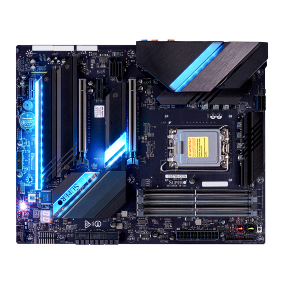
Introduction Congratulations on purchasing your computer motherboard from an industry leader. Supermicro motherboards are designed to provide you with the highest standards in quality and performance. In addition to the motherboard, several important parts that are included in the retail box are listed below. - Page 9 Chapter 1: Introduction Figure 1-1. C9Z790-CGW Motherboard Image Differences between C9Z790-CG and C9Z790-CGW C9Z790-CG C9Z790-CGW CNVi M.2 E Key module for WiFi and Bluetooth Note: All graphics shown in this manual were based upon the latest PCB revision avail- able at the time of publication of the manual. The motherboard you received may or...
- Page 10 Super C9Z790-CG/-CGW User's Manual Figure 1-2. C9Z790-CG Motherboard Layout (not drawn to scale) MAC CODE MAC CODE BAR CODE DP/HDMI HD AUDIO 22110 USB0/1/2/3 LAN2 LAN1 USB8 (3.2, 10Gb) USB6 (3.2, 10Gb) USB9 (3.2, 20Gb) USB7 (3.2, 20Gb) JLED_IO LED18...
- Page 11 JPW1 LED1 SYS_FAN1 CPU_FAN1 CLEAR CMOS JSD1 I-SATA0 I-SATA2 I-SATA4 I-SATA1 I-SATA3 I-SATA5 SYS_FAN2 12V_PUMP_PWR1 Differences between C9Z790-CG and C9Z790-CGW C9Z790-CG C9Z790-CGW CNVi M.2 E Key module for WiFi and Bluetooth Note: Components not documented are for internal testing only.
-
Page 12: Quick Reference
Super C9Z790-CG/-CGW User's Manual Quick Reference M.2-P1 JLED_POGO1 M.2-E1 (CNVi) LAN2 LAN1 USB0 USB8 USB6 USB1 HDMI M.2-P2 M.2-C1 HD AUDIO USB9 USB7 USB2 USB3 LED2 JLED_IO SLOT1 SLOT4 SLOT5 SLOT7 MAC CODE MAC CODE BAR CODE DP/HDMI AUDIO FP... -
Page 13: Quick Reference Table
Chapter 1: Introduction Quick Reference Table Jumper Description Default Setting CLEAR CMOS Clear CMOS Button Push Button Switch Pins 1-4: External Speaker Speaker / Buzzer Pins 3-4: Buzzer (Default) JPME2 Intel Manufacturing Mode Pins 1-2: Normal JWD1 Watch Dog Function Enable Pins 1-2: Reset POWER BUTTON Internal Power Button... - Page 14 Super C9Z790-CG/-CGW User's Manual Connector Description 12V_PUMP_PWR1 12V 4-pin Power Connector (for CPU Liquid Cooling Pump) AUDIO FP Front Panel Audio Header Onboard Battery COM1 COM Header CPU_FAN1, CPU_FAN2 CPU_FAN1, CPU_FAN2: CPU Fan Headers SYS_FAN1 - SYS_FAN3 SYS_FAN1 - SYS_FAN3: System Fan Headers DP/HDMI Back Panel DisplayPort 1.4b / High-Definition Multimedia Interface 2.1...
-
Page 15: Motherboard Features
DIMM Size • Up to 128GB Note 1: Memory capacity and frequency is CPU dependent. Note 2: For the latest CPU/memory updates, please refer to our website at http://www.supermicro.com/products/ motherboard. Chipset • Intel PCH Z790 Expansion Slots •... - Page 16 Super C9Z790-CG/-CGW User's Manual Motherboard Features BIOS • 256Mb AMI BIOS SPI Flash BIOS ® • ACPI 6.0, Plug and Play (PnP), BIOS rescue hot-key, riser card auto detection support, and SMBIOS 3.0 or later Power Management • ACPI power management •...
- Page 17 FLASH TPM2.0 Header SPI 128Mb Head Phone Header Differences between C9Z790-CG and C9Z790-CGW C9Z790-CG C9Z790-CGW CNVi M.2 E Key module for WiFi and Bluetooth No Note: This is a general block diagram and may not exactly represent the features on your motherboard.
-
Page 18: Processor And Chipset Overview
Gen. Intel Core i9/i7/i5/i3, Pentium, and Celeron series processors (LGA1700 socket) and the Intel PCH Z790 chipset, the C9Z790-CG/-CGW motherboard provides system performance, power efficiency, and feature sets to address the needs of next-generation computer users. With the support of the new Intel Microarchitecture 10nm Enhanced SuperFin Process Technology, the C9Z790-CG/-CGW dramatically increases system performance for a multitude of server applications. -
Page 19: System Health Monitoring
Chapter 1: Introduction 1.4 System Health Monitoring Onboard Voltage Monitors An onboard voltage monitor will scan the voltages of the onboard chipset, memory, CPU, and battery continuously. Once a voltage becomes unstable, a warning is given, or an error message is sent to the screen. The user can adjust the voltage thresholds to define the sensitivity of the voltage monitor. -
Page 20: Acpi Features
It is even more important for processors that have high CPU clock rates where noisy power transmission is present. The C9Z790-CG/-CGW motherboard accommodates a 24-pin ATX power supply. Although most power supplies generally meet the specifications required by the CPU, some are inadequate. -
Page 21: Serial Header
Chapter 1: Introduction 1.7 Serial Header The C9Z790-CG/-CGW motherboard supports one serial communication connection. The COM header can be used for input/output. The UART provides legacy speeds with a baud rate of up to 115.2 Kbps as well as an advanced speed with baud rates of 250 K, 500 K, or 1 Mb/s, which support high-speed serial communication devices. -
Page 22: Chapter 2 Installation
Super C9Z790-CG/-CGW User's Manual Chapter 2 Installation 2.1 Static-Sensitive Devices Electrostatic Discharge (ESD) can damage electronic components including memory modules. To avoid damaging your motherboard or your system, it is important to handle them very carefully. The following measures are generally sufficient to protect your equipment from ESD. -
Page 23: Processor And Heatsink Installation
If you buy a CPU separately, make sure that you use an Intel-certified multi-directional heatsink only. • Refer to the Supermicro website for updates on processor support. • All graphics in this manual are for illustrations only. Your components may look different. - Page 24 Super C9Z790-CG/-CGW User's Manual 2. Gently push down the load lever to release and lift it, then lift the load plate to open it completely. Lever lock 3. Use your thumb and your index finger to hold the CPU. Align the small triangle marker and notches on the CPU to the corresponding triangle marker and notches on the CPU load bracket.
- Page 25 Chapter 2: Installation 6. Close the load plate with the CPU inside the socket. Gently push the load lever down until it locks under the Lever Lock latch. Lever lock Attention! You can only install the CPU inside the socket in one direction. Make sure that it is properly inserted into the CPU socket before closing the load plate.
-
Page 26: Installing A Cpu Heatsink
Super C9Z790-CG/-CGW User's Manual Installing a CPU Heatsink Note 1: The installation described in this section is for reference only. The actual in- stallation steps may vary depending on the CPU heatsink model. Please refer to the heatsink instruction for more details. - Page 27 Chapter 2: Installation 3. Attach the backplate into the mounting holes around the CPU socket on the bottom side of the motherboard. Backplate bottom side Motherboard bottom side Mounting hole Motherboard Top side...
- Page 28 Super C9Z790-CG/-CGW User's Manual 4. Apply the proper amount of thermal grease on the CPU. 5. Place the heatsink on top of the CPU so that the four mounting holes on the heatsink are aligned with those on the retention mechanism.
-
Page 29: Removing A Cpu Heatsink
Chapter 2: Installation Removing a CPU Heatsink Warning: We do not recommend that the CPU or heatsink be removed. However, if you do need to remove the heatsink, please follow the instruction below to uninstall the heatsink to avoid damaging the CPU or other components. 1. -
Page 30: Motherboard Installation
Super C9Z790-CG/-CGW User's Manual 2.3 Motherboard Installation All motherboards have standard mounting holes to fit different types of chassis. Make sure that the locations of all the mounting holes for both the motherboard and the chassis match. Although a chassis may have both plastic and metal mounting fasteners, metal ones are highly recommended because they ground the motherboard to the chassis. -
Page 31: Installing The Motherboard
Chapter 2: Installation Installing the Motherboard 1. Install the I/O shield into the back of the chassis, if applicable. 2. Locate the mounting holes on the motherboard. Refer to the previous page for the location. 3. Locate the matching mounting holes on the chassis. Align the mounting holes on the motherboard against the mounting holes on the chassis. -
Page 32: Memory Support And Installation
Super C9Z790-CG/-CGW User's Manual 2.4 Memory Support and Installation Note: Check the Supermicro website for recommended memory modules. Important: Exercise extreme care when installing or removing DIMM modules to pre- vent any possible damage. General Guidelines for Optimizing Memory Performance •... - Page 33 Chapter 2: Installation Memory Population Table Recommended Population (Balanced) DIMMA1 DIMMB1 DIMMA2 DIMMB2 Total System Memory 8GB DIMM 8GB DIMM 16GB 8GB DIMM 8GB DIMM 8GB DIMM 8GB DIMM 32GB 16GB DIMM 16GB DIMM 32GB 16GB DIMM 16GB DIMM 16GB DIMM 16GB DIMM 64GB 32GB DIMM...
-
Page 34: Dimm Installation
Super C9Z790-CG/-CGW User's Manual DIMM Installation MAC CODE MAC CODE BAR CODE DP/HDMI 1. Insert DIMM modules in the following 22110 HD AUDIO USB0/1/2/3 LAN2 LAN1 USB8 (3.2, 10Gb) USB6 (3.2, 10Gb) USB9 (3.2, 20Gb) USB7 (3.2, 20Gb) JLED_IO 22110... -
Page 35: Installation (Optional)
Chapter 2: Installation 2.5 M.2 Installation (optional) The motherboard has three PCIe M.2 M-key sockets that support the M.2 2260/2280/22110 modules (M.2-P1 and M.2-P2), and 2260/2280 modules (M.2-C1). Refer to the illustration on the right for the locations of M.2 sockets and mounting holes. Follow the steps below in order to install an M.2 device. - Page 36 Super C9Z790-CG/-CGW User's Manual 3. Installation WITH pre-installed standoffs: Insert the M.2 device into the M.2 socket at a 30-degree angle and press it down. Installation WITHOUT pre-installed standoffs: Install the standoff to the intended mounting hole first. Then insert the M.2 device into the M.2 socket at a 30-degree angle and press it down.
- Page 37 Chapter 2: Installation 5. To install the heatsink correctly, make sure Pogo Pin the pogo pin contacts are properly touching Contacts the pogo pins on the motherboard. Refer to the illustration on the right for the locations Heatsink with Pogo Pin Header LED for M.2-C1 (JLED_POGO2) of pogo pin contacts and pogo pin headers...
-
Page 38: Rear I/O Ports
Super C9Z790-CG/-CGW User's Manual 2.6 Rear I/O Ports Refer to Figure 2-1 below for the locations and descriptions of the various I/O ports on the rear of the motherboard. MAC CODE MAC CODE BAR CODE DP/HDMI HD AUDIO 22110 USB0/1/2/3... - Page 39 Chapter 2: Installation Universal Serial Bus (USB) Ports Four USB 2.0 Type-A ports (USB0/1/2/3), two USB 3.2 Gen 2 Type-A ports (USB6/8), and two USB 3.2 Gen 2x2 Type-C ports (USB7/9) are located on the I/O back panel. In addition, one front panel USB 2.0 header (USB4/5), one USB 3.2 Gen 1 header (USB10/11), and one USB 3.2 Gen 2x2 20-pin connector (USB12) are also located on the motherboard to provide front chassis access using USB cables (not included).
- Page 40 Super C9Z790-CG/-CGW User's Manual Back Panel High Definition Audio (HD Audio) This motherboard features a 7.1+2 Channel High Definition Audio (HDA) codec that provides 10 DAC channels. The HD Audio connections simultaneously supports multiple-streaming 7.1 sound playback with 2 channels of independent stereo output through the front panel stereo out for front, rear, center and subwoofer speakers.
- Page 41 Chapter 2: Installation DisplayPort Port DisplayPort 1.4b, developed by the VESA consortium, delivers digital display at a fast refresh rate. It can connect to virtually any display device using a DisplayPort adapter for devices, such as VGA, DVI, and HDMI. HDMI Port One High-Definition Multimedia Interface (HDMI) 2.1 port is located on the I/O back panel.
-
Page 42: Front Control Panel
JF1 contains header pins for various buttons and indicators that are normally located on a control panel at the front of the chassis. These connectors are designed specifically for use with Supermicro chassis. Refer to the figure below for the descriptions of the front control panel buttons and LED indicators. - Page 43 Chapter 2: Installation Power LED The Power LED connection is located on pins 15 and 16 of JF1. Refer to the table below for pin definitions. Power LED Pin Definitions (JF1) Pin# Definition Power LED (-) Vcc / Power LED (+) HDD LED The HDD LED connection is located on pins 13 and 14 of JF1.
- Page 44 Super C9Z790-CG/-CGW User's Manual NIC1/NIC2 (LAN1/LAN2) LED The Network Interface Controller (NIC) LED connection for LAN1/LAN2 is located on pins 9/11 and 10/12 of JF1. Attach an LED indicator to this header to display network activity. Refer to the table below for pin definitions.
- Page 45 Chapter 2: Installation Reset Button The Reset Button connection is located on pins 3 and 4 of JF1. Attach it to a hardware reset switch on the computer case to reset the system. Refer to the table below for pin definitions. Reset Button Pin Definitions (JF1) Pin#...
-
Page 46: Connectors
Super C9Z790-CG/-CGW User's Manual 2.8 Connectors This section provides brief descriptions and pinout definitions for onboard headers and connectors. Be sure to use the correct cable for each header or connector. Power Connections ATX Power Supply Connector The 24-pin power supply connector (JPW1) meets the ATX SSI EPS 12V specification. You must also connect the 8-pin (JPW2) processor power connector to the power supply. - Page 47 Chapter 2: Installation 8-Pin Power Connector JPW2 is an 8-pin 12V DC power input for the CPU that must be connected to the power supply. Refer to the table below for pin definitions. 8-pin Power Pin Definitions Pin# Definition 1 - 4 Ground 5 - 8 +12V...
-
Page 48: Headers
Super C9Z790-CG/-CGW User's Manual Headers Fan Headers There are five 4-pin fan headers (CPU_FAN1 - CPU_FAN2, SYS_FAN1 - SYS_FAN3) on the motherboard. Although pins 1-3 of the system fan headers are backwards compatible with the traditional 3-pin fans, the 4-pin fans are recommended to take advantage of the fan speed control. - Page 49 Chapter 2: Installation Chassis Intrusion Header A Chassis Intrusion header is located at JL1 on the motherboard. Attach the appropriate cable from the chassis to inform you of a chassis intrusion when the chassis is opened. Refer to the table below for pin definitions. Chassis Intrusion Header Pin Definitions Pin#...
- Page 50 Super C9Z790-CG/-CGW User's Manual Power LED Header An onboard Power LED header is located at JLED1. This Power LED header is connected to the Front Control Panel located at JF1 to indicate the status of system power. Refer to the table below for pin definitions.
- Page 51 Chapter 2: Installation Addressable RGB (ARGB) LED Connection Header The motherboard has two +5V ARGB connection headers (JRLED1/2) for connection to optional ARGB LED device such as an LED strip or LED fan. If connecting to an ARGB LED fan, also connect the fan's power connector to one of the motherboard's fan headers (SYS_FAN1 - SYS_FAN3).
- Page 52 Super C9Z790-CG/-CGW User's Manual DOM PWR Connector The Disk-On-Module (DOM) power connector, located at JSD1, provides 5V power to a solid state DOM storage device connected to one of the SATA ports. Refer to the table below for pin definitions.
- Page 53 SATA ports provide serial-link signal connections, which are faster than the connections of Parallel ATA. Note: For more information on the SATA HostRAID configuration, please refer to the Intel SATA HostRAID user's guide posted on our website at https://www.supermicro. com/support/manuals/. 1. M.2-P1 MAC CODE...
- Page 54 Super C9Z790-CG/-CGW User's Manual Front Panel Audio Header A 10-pin Audio header at AUDIO FP is supported on the motherboard. This header allows you to connect the motherboard to a front panel audio control panel, if needed. Connect an audio cable to the audio header to use this feature (not supplied). Refer to the table below for pin definitions.
- Page 55 Port 80 connection. Use this header to enhance system performance and data security. Refer to the table below for pin definitions. Please go to the following link for more information on the TPM: https://www.supermicro.com/manuals/other/AOM-TPM-9670V_9670H.pdf. TPM/Port 80 Header Pin Definitions...
-
Page 56: Jumper Settings
Super C9Z790-CG/-CGW User's Manual 2.9 Jumper Settings How Jumpers Work To modify the operation of the motherboard, jumpers can be used to choose between optional settings. Jumpers create shorts between two pins to change the function of the connector. Pin 1 is identified with a square solder pad on the printed circuit board. Refer to the diagram below for an example of jumping pins 1 and 2. - Page 57 Chapter 2: Installation Clear CMOS/SW1 Button Clear CMOS Button is used to clear the saved system setup configuration stored in the CMOS chip. All the settings will be erased and restored to the factory defaults after pressing this button. On this motherboard, there are two buttons which built-in this function. One is the SW1 button located on the I/O back panel and the other is the Clear CMOS button located next to the Reset Button.
- Page 58 Super C9Z790-CG/-CGW User's Manual Manufacturing Mode Close pins 2 and 3 of JPME2 to bypass SPI flash security and force the system to operate in Manufacturing Mode, allowing you to flash the system firmware from a host server for system setting modifications.
-
Page 59: Led Indicators
Chapter 2: Installation 2.10 LED Indicators LAN1 LEDs The LED of LAN1 on the left indicates the speed of the connection, and the LED of LAN1 on the right indicates activity. Refer to the tables below for more information. LAN1 Link Indicator LAN1 Activity Indicator LED Settings LED Settings... - Page 60 Super C9Z790-CG/-CGW User's Manual M.2 LED Three M.2 LEDs are provided and indicated the status of connected M.2 devices. When an M.2 LED is blinking, the corresponding M.2 device is functioning normally. These LEDs are located nearby the corresponding M.2 sockets. Refer to the table below for the status information.
- Page 61 Chapter 2: Installation Power LED An onboard power LED is located at LED1 on the motherboard. When LED1 is on, the AC power cable is connected. Make sure to disconnect the power cable before removing or installing any component. Refer to the tables below for more information. Power LED Indicator LED Status Status...
-
Page 62: Chapter 3 Troubleshooting
Super C9Z790-CG/-CGW User's Manual Chapter 3 Troubleshooting 3.1 Troubleshooting Procedures Use the following procedures to troubleshoot your system. If you have followed all of the procedures below and still need assistance, refer to the ‘Technical Support Procedures’ and/ or ‘Returning Merchandise for Service’ section(s) in this chapter. Always disconnect the AC power cord before adding, changing or installing any non hot-swap hardware components. -
Page 63: No Video
Chapter 3: Troubleshooting No Video 1. If the power is on, but you have no video, remove all add-on cards and cables. 2. Use the speaker to determine if any beep codes are present. Refer to Appendix A for details on beep codes. 3. -
Page 64: Losing The System's Setup Configuration
Super C9Z790-CG/-CGW User's Manual Losing the System's Setup Configuration 1. Make sure that you are using a high-quality power supply. A poor-quality power supply may cause the system to lose the CMOS setup information. Refer to Section 1.6 Power Supply for details on recommended power supplies. -
Page 65: Technical Support Procedures
Before contacting Technical Support, please take the following steps. Also, please note that as a motherboard manufacturer, Supermicro also sells motherboards through its channels, so it is best to first check with your distributor or reseller for troubleshooting services. They should know of any possible problems with the specific system configuration that was sold to you. -
Page 66: Frequently Asked Questions
Note: The SPI BIOS chip used on this motherboard cannot be removed. Send your moth- erboard back to our RMA Department at Supermicro for repair. For BIOS Recovery instruc- tions, please refer to the AMI BIOS Recovery Instructions posted at http://www.supermi-... -
Page 67: Battery Removal And Installation
Chapter 3: Troubleshooting 3.4 Battery Removal and Installation Battery Removal To remove the onboard battery, follow the steps below: 1. Power off your system and unplug your power cable. 2. Locate the onboard battery as shown below. 3. Using a tool such as a pen or a small screwdriver, push the battery lock outwards to unlock it. -
Page 68: Returning Merchandise For Service
Super C9Z790-CG/-CGW User's Manual 3.5 Returning Merchandise for Service A receipt or copy of your invoice marked with the date of purchase is required before any warranty service will be rendered. You can obtain service by calling your vendor for a Returned Merchandise Authorization (RMA) number. -
Page 69: Chapter 4 Uefi Bios
Chapter 4: UEFI BIOS Chapter 4 UEFI BIOS 4.1 Introduction This chapter describes the AMIBIOS™ Setup utility for the motherboard. The BIOS is stored on a chip and can be easily upgraded using a flash program. Notes: 1. Due to periodic changes to the BIOS, some settings may have been added or deleted and might not yet be recorded in this manual. - Page 70 Super C9Z790-CG/-CGW User's Manual The AMI BIOS GUI Setup Utility uses a mouse pointer navigation system similar to standard graphical user interfaces. Hover and click an icon to select a section, click a down arrow to select from an options list.
-
Page 71: Ez Mode
Chapter 4: UEFI BIOS 4.2 EZ Mode While in EZ Mode, the following information will be displayed: • BIOS Version - The current BIOS version. • CPU Information - The model, speed, and voltage of installed CPU. • Memory Frequency - The frequency of installed memory. •... - Page 72 Super C9Z790-CG/-CGW User's Manual • Fan Profile - Displays current fan speeds, or click the SMC QFAN Setting ( ) using the mouse cursor for more advanced adjustments. SMC QFan Setting Temperatures Note: The SMC QFAN Setting page has a user friendly graphical interface. You can also configure these features in the section of H/W Monitor >...
- Page 73 Chapter 4: UEFI BIOS also increase for effective system cooling. Select "Full Speed" to allow the onboard fans to run at full speed (of 100% Pulse Width Modulation Duty Cycle) for maximum cooling. This setting is recommended for special system configuration or debugging. Select "Stable"...
-
Page 74: Main
Super C9Z790-CG/-CGW User's Manual 4.3 Main BIOS Information The following items will be displayed: BIOS Version - This feature displays the version of the BIOS ROM used in the system. Build Date - This feature displays the date of when the BIOS ROM version used in the system was built. - Page 75 Chapter 4: UEFI BIOS System Date/System Time Use this feature to change the system date and time. Highlight System Date or System Time using the arrow keys. Enter new values using the keyboard. Press the <Tab> key or the arrow keys to move between fields. The date must be entered in MM/DD/YYYY format. The time is entered in HH:MM:SS format.
-
Page 76: Overclocking
Super C9Z790-CG/-CGW User's Manual 4.4 Overclocking Note: Overclocking feature is available only when your CPU supports overclocking. Overclocking Feature This feature enables the CPU overclocking. The options are Enabled and Disabled. *If this feature is set to Enabled, the following features will become available for... - Page 77 Chapter 4: UEFI BIOS the "Turbo Ratio Limit (TRL) MSR 0x1AD / 0x1AE" setting based on the setting here. The options are Disabled and Enabled. CPU Core Ratio This feature determines the core ratio control of CPU. The options are Auto, Sync All Cores, and Per Core.
- Page 78 Super C9Z790-CG/-CGW User's Manual Core Max OC Ratio This feature controls the general maximum overclocking ratio for the CPU cores and Ring. The default is 44 (Auto). This feature enables the AVX 2/3 Instructions. This is applicable for big core only. The options are Enabled and Disabled.
- Page 79 Chapter 4: UEFI BIOS *If this feature above is set to Enabled, the following features will become available for configuration: Power Limit 1 This feature configures the Power Limit 1 in milliwatts. When the limit is exceeded, the CPU ratio is lowered after a period of time (see item below). A lower limit can save power and protect the CPU, while a higher limit improves performance.
- Page 80 Super C9Z790-CG/-CGW User's Manual GT ICC Max Current Limit Override This feature controls the GT voltage regular current limit (Icc Max). The value is in 1/4 A increments. The range is 4-2047 and the default is 168. GT ICC Unlimited Mode This feature This feature disables or enables the GT unlimited ICCMAX.
- Page 81 Chapter 4: UEFI BIOS Per-core HT Disable Defines the per-core HT disable. Use the number keys on your keyboard to enter the value. The default setting is 0. Race To Halt (RTH) This feature enables Race To Halt, which dynamically increases CPU frequency in order to enter package C-State faster.
- Page 82 Super C9Z790-CG/-CGW User's Manual Ring Down Bin This feature enables Ring Down Bin. If set to Enabled, the maximum ring ratio will not be observed. The options are Disabled and Enabled. Min Ring Ratio Limit Enter a value for the minimum ratio limit for CPU Ring. The default is Auto.
- Page 83 Chapter 4: UEFI BIOS VccIn Aux IMON Slope Enter a value for the VccIn Aux IMON Slope. The range is 0-200 in 1/100 increments and the default is 100. VccIn Aux IMON Offset Enter a value for the VccIn Aux IMON Offset. The range is 0-63999 and the default is 0. VccIn Aux IMON Prefix Use this feature to set the prefix value as a positive (+) or a negative (-).
- Page 84 Super C9Z790-CG/-CGW User's Manual *If the feature of Acoustic Noise Mitigation is set to Enabled, the following features will become available for configuration: Pre Wake Time / Ramp Up Time / Ramp Down Time Enter a value for the desired feature. The range is 0-255. The default is 0.
- Page 85 Chapter 4: UEFI BIOS PS Current Threshold1 Enter a value for PS Current Threshold1. The range is 0-512 in 1/4 A increments. The default is 80. PS Current Threshold2 Enter a value for PS Current Threshold2. The range is 0-512 in 1/4 A increments. The default is 20.
- Page 86 Super C9Z790-CG/-CGW User's Manual TDC Current Limit Enter a value for the TDC Current Limit, with each whole number equating to 1/8A (i.e., 1000 = 125A). The range is 0-32767. The default is 0. TDC Time Windows This feature controls the TDC Time Window. The default is 1 sec.
- Page 87 Chapter 4: UEFI BIOS GT Voltage Mode This feature controls the voltage mode in the GT domain. The options are Adaptive and Override. *If the feature of GT Voltage Mode is set to Adaptive, the following feature will become available for configuration: GT Extra Turbo Voltage Enter a value for the extra turbo voltage (in mV) that will be applied while GT is operating in turbo mode.
- Page 88 Super C9Z790-CG/-CGW User's Manual Advanced Memory OC Setting *The features below are available when the Memory Profile is set to Custom profile. Realtime Memory Timing This feature enables Realtime Memory Timing changes to be made after MRC_DONE. The options are Disabled and Enabled.
- Page 89 Chapter 4: UEFI BIOS tRFC2 This feature configures the Minimum Refrech Recovery Delay Time. Enter a value be- tween 0-15000 and the default is 0 for Auto. tRTP This feature configures the Minimum Internal Read to Precharge Command Delay Time. Enter a value between 0-15 where 0 is for Auto.
- Page 90 Super C9Z790-CG/-CGW User's Manual UnderVolt Protection Use this feature to determine if a user can perform CPU undervolting in OS runtime. It's recommended to set this feature to Enabled, which enables the protection and CPU undervolting in OS runtime is not allowed. If disabled, there is no protection and undervolting in OS runtime is allowed.
- Page 91 Chapter 4: UEFI BIOS Offset Prefix Use this feature to set the prefix value as a positive (+) or a negative (-). The options are “+” and “-”. *If the feature of VF Configuration Scope is set to Per-core, the following features will become available for configuration: P-core 0/1/2/3/4/5 Voltage Offset Enter a value for the offset voltage (in mV) that will be applied to the performance-core...
- Page 92 Super C9Z790-CG/-CGW User's Manual GT Voltage Mode This feature controls the voltage mode in the GT domain. The options are Adaptive and Override. *If the feature of GT Voltage Mode is set to Adaptive, the following feature will become available for configuration:...
- Page 93 Chapter 4: UEFI BIOS *If the feature of E-Core L2 Voltage Mode is set to Override, the following feature will become available for configuration: E-core L2 Voltage Override Use this feature to specify the override voltage applied to the E-core L2 domain (in mV).
- Page 94 Super C9Z790-CG/-CGW User's Manual Ring Voltage Offset Enter a value for the offset voltage (in mV) that will be applied to the ring domain. The range is -500 to 500 and the default is 0. Offset Prefix Use this feature to set the prefix value as a positive (+) or a negative (-). The op- tions are “+”...
- Page 95 Chapter 4: UEFI BIOS Voltage PLL Trim Controls Core PLL Voltage Offset / GT PLL Voltage Offset / Ring PLL Voltage Offset / System Agent PLL Voltage Offset / Memory Controller PLL Voltage Offset Enter a desired numeric value above for each feature. This feature can be used to in- crease the range of this domain frequency in extreme overclocking conditions.
-
Page 96: Advanced
Super C9Z790-CG/-CGW User's Manual 4.5 Advanced Setup Mode This feature sets the default mode to start in after entering BIOS. The options are EZ Mode and Advanced Mode. CPU Cooler Tuning Manual Power Limit 1: 125.0W Manual Power Limit 2: 125.0W... - Page 97 Chapter 4: UEFI BIOS Boot Feature Boot Feature Fast Boot This feature enables the system to boot with a minimal set of required devices to launch. This has no effect on BBS boot options. The options are Disabled and Enabled. Quiet Boot Use this feature to select the screen display between the POST messages and the OEM logo upon boot up.
- Page 98 Super C9Z790-CG/-CGW User's Manual Note: This feature is available only for non-ACPI OS and Pre-OS. DeepSx Power Policies This feature enables DeepSx Power Policy configuration. The options are Disabled, Enabled in S4-S5, and Enabled in S5. Connectivity Configuration Note: This submenu is available only for C9Z790-CGW.
- Page 99 Chapter 4: UEFI BIOS • L1 Instruction Cache • L2 Cache • L3 Cache • VMX • SMX/TXT C6DRAM This feature enables moving DRAM contents to PRM memory when the CPU is in a C6 state. The options are Disabled and Enabled. Note: This feature is available depending on the CPU installed.
- Page 100 Super C9Z790-CG/-CGW User's Manual Graphics Configuration Graphics Configuration Note: Only the feature of Primary Display is available for configuring in this submenu if the installed CPU doesn’t have integrated graphics. Graphics Turbo IMON Current Enter a value for the graphics turbo IMON current. The range is 14-31 and the default is 31.
- Page 101 Chapter 4: UEFI BIOS Cdynmax Clamping Enable This feature enables Cdynmax Clamping. The options are Enabled and Disabled. Graphics Clock Frequency This feature controls the graphics clock frequency. Select the highest clock frequency supported by the platform. The options are 192 Mhz, 307.2 Mhz, 326.4 Mhz, 556.8 Mhz, 652.8 Mhz, and Max CdClock freq based on Reference Clk.
- Page 102 Risk!!). Warning: Disabling this option is a violation of RFC 6125 and may expose you to Man-in- the-Middle Attacks. Supermicro computer, Inc. is not responsible for any and all security risks incurred by you disabling this option. Priority of HTTP Boot Instance of Priority 1 Use this feature to rank the targeted port.
- Page 103 Chapter 4: UEFI BIOS Memory configuration The following memory information will be displayed: • Memory RC Version • Memory Frequency • Memory Timings (tCL-tRCD-tRP-tRAS) • DIMMA1 / DIMMA2 / DIMMB1 / DIMMB2 Maximum Memory Frequency This feature selects the type/speed of the memory installed. The default is Auto and all values are in MHz.
- Page 104 Super C9Z790-CG/-CGW User's Manual NCT6796DE Super IO Configuration Super IO Chip Displays the information of the super IO chip (NCT6796DE). Serial Port 1 Configuration Serial Port 1 Configuration Serial Port 1 This feature will enable or disable Serial Port 1 (COM1). Check the box to enable Serial Port 1.
- Page 105 Chapter 4: UEFI BIOS MAC: XXXXXXXXXXXX-IPv4 Network Configuration Configured Use this feature to configure the network settings. The default is Unchecked. *If the feature of Configured is set to checked, the following features will become available for configuration: Enable DHCP Use this feature to set the DHCP.
- Page 106 Super C9Z790-CG/-CGW User's Manual Interface ID Enter the 64-bit alternative interface ID for the device. DAD Transmit Count Enter a value for Duplicate Address Detection (DAD) Transmit Count. A value of zero indicates the DAD is not performed. The default is 1.
- Page 107 Chapter 4: UEFI BIOS • ME Firmware Version • ME Firmware Mode • ME Firmware SKU ME FW Image Re-Flash This feature enables an update to the PCH firmware from an image in a USB flash drive attached to a USB port. The options are Disabled and Enabled. TPM Device Selection Use this feature to select the TPM device.
- Page 108 Super C9Z790-CG/-CGW User's Manual PCH SLOT1 ASPM This feature configures the Active State Power Management (ASPM) settings for PCH SLOT1. The options are Disabled, L1, and Auto. PCH SLOT1 L1 Substates This feature configures the L1 substate for PCH SLOT1. The options are Disabled, L1.1, and L1.1 &...
- Page 109 Chapter 4: UEFI BIOS NVMe Firmware Source Use this feature to select the NVMe firmware to support booting. The options are Vendor Defined Firmware and AMI Native Support. The default option, Vendor Defined Firmware, is pre-installed on the drive and may resolve errata or enable innovative functions for the drive.
- Page 110 Super C9Z790-CG/-CGW User's Manual C-States C-States architecture, a processor power management platform developed by Intel, can further reduce power consumption from the basic C1 (Halt State) state that blocks clock cycles to the CPU. Select Enabled for CPU C-Sates support. The options are Disabled and Enabled.
- Page 111 Chapter 4: UEFI BIOS GT - Power Management Control Note: This submenu becomes configurable when the installed CPU has built-in inte- grated graphics. GT - Power Management Control RC6 (Render Standby) Use this feature to enable Render Standby support. The options are Disabled and En- abled.
- Page 112 Super C9Z790-CG/-CGW User's Manual SATA0-5 Note: If the SATA controller has been mapped under VMD, then SATA storage devices information will not be displayed. Hot Plug This feature designates the port specified for hot plugging. Set the setting to Enabled for hot-plugging support, which will allow you to replace a SATA disk drive without shutting down the system.
- Page 113 Chapter 4: UEFI BIOS *If this feature is set to Disabled, the following feature will become available for configuration: Map this Root Port under VMD Use this feature to map or unmap a Root Port to VMD. The options are Disabled and Enabled.
- Page 114 Super C9Z790-CG/-CGW User's Manual Key Management Key Management Restore Factory Keys This feature resets the content of all UEFI Secure Boot key databases to factory defaults. Reset to Setup Mode This feature deletes the contents of all UEFI Secure Boot key databases. This will result in entering Setup Mode.
- Page 115 Chapter 4: UEFI BIOS Key Exchange Keys Details Review details on current settings of the Key Exchange Keys. Export This feature allows you to export Key Exchange Keys to an available file system. Update Select Yes to load the KEK from the manufacturer's defaults. Select No to load the KEK from a file.
- Page 116 Super C9Z790-CG/-CGW User's Manual Forbidden Signatures Details Review details on current settings of the Forbidden Signatures. Export This feature allows you to export Forbidden Signatures to an available file system. Update Select Yes to load the DBX factory default 'dbx.' Select No to load it from an external file.
- Page 117 Chapter 4: UEFI BIOS OsRecovery Signatures Details Review details on current settings of the OsRecovery Signatures. Export This feature allows you to export OsRecovery Signatures to an available file system. Update Select Yes to load the DBT from the manufacturer's defaults. Select No to load the DBT from a file.
- Page 118 HDD User Pwd Status This feature indicates if a password has been set as a SATA user password which will allow the user to configure Supermicro Security Erase settings on the HDD (SATA) device by using this SATA user password.
- Page 119 Chapter 4: UEFI BIOS Serial Port Configuration COM1 COM1 Console Redirection Check the box to enable console redirection support for a serial port specified by you. The options are Unchecked and Checked. * If this feature above is set to Checked, the following features will become available for configuration: COM1 Console Redirection Settings COM1 Terminal Type...
- Page 120 Super C9Z790-CG/-CGW User's Manual COM1 Stop Bits A stop bit indicates the end of a serial data packet. Select 1 (Stop Bit) for standard serial data communication. Select 2 (Stop Bits) if slower devices are used. The options are 1 and 2.
- Page 121 Chapter 4: UEFI BIOS * If the feature of Console Redirection is set to Checked, the following features will become available for configuration: Console Redirection Settings Console Redirection Settings This feature allows you to specify how the host computer will exchange data with the client computer, which is the remote computer used by you.
- Page 122 Super C9Z790-CG/-CGW User's Manual System Agent (SA) Configuration VT-d This feature displays if VT-d capability is supported. PEG Port Configuration PEG 0:6:0(PCIE M.2- C1) Enable Root Port Select Enable to activate the Root Port. The options are Disabled and Enabled.
- Page 123 Chapter 4: UEFI BIOS Trusted Computing Note: This feature is appeared and available for configuration when a TPM 2.0 device is installed. Trusted Computing The following information will be displayed: TPM 2.0 Device Found • Firmware Version • Vendor Security Device Support This feature enables BIOS support for security devices.
- Page 124 Super C9Z790-CG/-CGW User's Manual Storage Hierarchy This feature enables Storage Hierarchy. The options are Disabled and Enabled. Endorsement Hierarchy This feature enables Endorsement Hierarchy. The options are Disabled and Enabled. TPM 2.0 InterfaceType This feature displays the TPM 2.0 interface type.
- Page 125 Chapter 4: UEFI BIOS Enroll Certification Using File Use this feature to enroll the certification from a file. Certification GUID Use this feature to input the certification Global Unique Identifier (GUID). Commit Changes and Exit Use this feature to save all changes and exit TLS settings. Discard Changes and Exit Use this feature to discard all changes and exit TLS settings.
- Page 126 Super C9Z790-CG/-CGW User's Manual Intel(R) Rapid Storage Technology This submenu is available only when Advanced > VMD setup menu > "Enabled VMD controller" feature is set to Enabled and the changes have been applied by clicking Save & Exit. Intel(R) RST 19.0.0.5428 RST VMD Driver Create RAID Volume...
- Page 127 Chapter 4: UEFI BIOS Capacity (GB) Enter the capacity in gigabytes (GB) of the RAID volume to be created. Create Volume After finishing the configuration of the Create RAID Volume feature, select Create Volume and you will return to the previous screen displaying the information about the created RAID volume.
-
Page 128: H/W Monitor
Super C9Z790-CG/-CGW User's Manual 4.6 H/W Monitor System Temperature The following items will be displayed: • CPU Temperature - the CPU temperature detected by PECI • System Temperature - the system internal temperature • Peripheral Temperature - the detected peripheral device temperature •... - Page 129 Chapter 4: UEFI BIOS Fan Control Fan Control Setting Fan Speed Control Mode This feature allows you to decide how the system controls the speeds of the onboard fans. The CPU temperature and the fan speed are correlative. When the CPU on-die temperature increases, the fan speed will also increase for effective system cooling.
-
Page 130: Boot
Super C9Z790-CG/-CGW User's Manual 4.7 Boot Fixed Boot order Priorities This feature prioritizes the order of a bootable device from which the system will boot. Press <Enter> on each item sequentially to select devices. UEFI Boot Option #1 - #9 The options are UEFI Hard Disk, UEFI CD/DVD, UEFI USB Hard Disk, UEFI USB CD/DVD, USB Key, UEFI USB Floppy, UEFI USB Lan, UEFI Network, UEFI AP, and Disabled. - Page 131 Chapter 4: UEFI BIOS Delete Boot Option Delete Boot Option Delete Boot Option Use this feature to remove an EFI boot option from the boot order. UEFI Hard Disk Drive BBS Priorities / UEFI NETWORK Drive BBS Priorities / UEFI Application Boot Priorities Note: These submenus are subject to change depending on the devices installed on this motherboard.
-
Page 132: Save & Exit
Super C9Z790-CG/-CGW User's Manual 4.8 Save & Exit Save Options Discard Changes and Exit Use this feature to exit the system without saving any changes and reboot the system. Save Changes and Exit Use this feature to save the changes you have made and reboot the system. -
Page 133: Appendix A Bios Codes
Appendix A: BIOS Codes Appendix A BIOS Codes A.1 BIOS Error POST (Beep) Codes During the Power-On Self-Test (POST) routines, which are performed each time the system is powered on, errors may occur. Non-fatal errors are those which, in most cases, allow the system to continue the boot-up process. -
Page 134: Additional Bios Post Codes
Super C9Z790-CG/-CGW User's Manual A.2 Additional BIOS POST Codes The AMI BIOS supplies additional checkpoint codes, which are documented online at https://www.supermicro.com/manuals/other/AMI_AptioV_BIOS_POST_Codes_for_SM_ Motherboards.pdf ("AMI BIOS POST Codes User's Guide"). For information on AMI updates, please refer to http://www.ami.com/products/. -
Page 135: Appendix B Software
Appendix B Software B.1 Driver Installation The Supermicro website that contains drivers and utilities for your system is at https://www. supermicro.com/wdl/driver/. Some of these must be installed, such as the chipset driver. After accessing the website, go into the CDR_Images (in the parent directory of the above link) and locate the ISO file for your motherboard. -
Page 136: Superdoctor 5
Super C9Z790-CG/-CGW User's Manual B.2 SuperDoctor 5 The Supermicro SuperDoctor 5 is a program that functions in a command-line or web-based interface for Windows and Linux operating systems. The program monitors such system health information as CPU temperature, system voltages, system power consumption, fan speed, and provides alerts via email or Simple Network Management Protocol (SNMP). -
Page 137: Appendix C Standardized Warning Statements
The following statements are industry standard warnings, provided to warn the user of situations which have the potential for bodily injury. Should you have questions or experience difficulty, contact Supermicro's Technical Support department for assistance. Only certified technicians should attempt to install or configure components. - Page 138 Super C9Z790-CG/-CGW User's Manual Attention Danger d'explosion si la pile n'est pas remplacée correctement. Ne la remplacer que par une pile de type semblable ou équivalent, recommandée par le fabricant. Jeter les piles usagées conformément aux instructions du fabricant. ¡Advertencia! Existe peligro de explosión si la batería se reemplaza de manera incorrecta.
- Page 139 Appendix C: Standardized Warning Statements Product Disposal Warning! Ultimate disposal of this product should be handled according to all na- tional laws and regulations. 製品の廃棄 この製品を廃棄処分する場合、 国の関係する全ての法律 ・ 条例に従い処理する必要があります。 警告 本产品的废弃处理应根据所有国家的法律和规章进行。 警告 本產品的廢棄處理應根據所有國家的法律和規章進行。 Warnung Die Entsorgung dieses Produkts sollte gemäß allen Bestimmungen und Gesetzen des Landes erfolgen.
Need help?
Do you have a question about the C9Z790-CG and is the answer not in the manual?
Questions and answers