Table of Contents
Advertisement
Quick Links
Advertisement
Table of Contents

Related Manuals for Supermicro C9X299-PG300


Summary of Contents for Supermicro C9X299-PG300
- Page 1 C9X299-PG300 USER MANUAL Revision 1.0...
- Page 2 State of California, USA. The State of California, County of Santa Clara shall be the exclusive venue for the resolution of any such disputes. Supermicro's total liability for all claims will not exceed the price paid for the hardware product.
-
Page 3: About This Manual
About This Manual This manual is written for system integrators, IT technicians and knowledgeable end users. It provides information for the installation and use of the C9X299-PG300 motherboard. About This Motherboard The Supermicro C9X299-PG300 motherboard supports one Intel® Core® X-Series processor in an LGA2066 socket. -
Page 4: Contacting Supermicro
C9X299-PG300 User's Manual Contacting Supermicro Headquarters Address: Super Micro Computer, Inc. 980 Rock Ave. San Jose, CA 95131 U.S.A. Tel: +1 (408) 503-8000 Fax: +1 (408) 503-8008 Email: marketing@supermicro.com (General Information) support@supermicro.com (Technical Support) Website: www.supermicro.com Europe Address: Super Micro Computer B.V. -
Page 5: Table Of Contents
Preface Table of Contents Chapter 1 Introduction 1.1 Checklist ..........................8 Quick Reference .......................11 Quick Reference Table ......................12 Motherboard Features .......................14 1.2 Processor and Chipset Overview ..................18 1.3 Special Features ........................18 Recovery from AC Power Loss ..................18 1.4 System Health Monitoring ....................19 Onboard Voltage Monitors ....................19 Fan Status Monitor with Firmware Control ...............19 Environmental Temperature Control .................19... - Page 6 C9X299-PG300 User's Manual DIMM Installation ......................31 DIMM Removal .........................31 Memory Population Guidelines ..................32 2.6 Rear I/O Ports ........................33 2.7 Front Control Panel ......................38 2.8 Connectors .........................43 Power Connections ......................43 Headers ..........................45 2.9 Jumper Settings .........................52 How Jumpers Work ......................52 2.10 LED Indicators ........................55 Chapter 3 Troubleshooting 3.1 Troubleshooting Procedures ....................57...
- Page 7 Preface 4.6 Advanced ..........................84 4.7 System Health ........................96 4.8 Boot .............................98 4.9 BIOS Update ........................100 Appendix A BIOS Codes Appendix B Software Installation B.1 Installing Software Programs ...................102 B.2 SuperDoctor 5 .........................103 ® Appendix C Standardized Warning Statements Battery Handling ......................104 Product Disposal ......................106 Appendix D UEFI BIOS Recovery...
-
Page 8: Chapter 1 Introduction
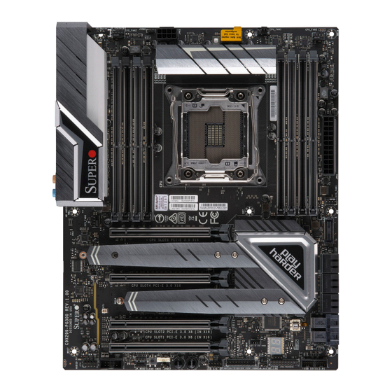
• Product safety info: http://www.supermicro.com/about/policies/safety_information.cfm • If you have any questions, please contact our support team at: support@supermicro.com This manual may be periodically updated without notice. Please check the Supermicro website for possible updates to the manual revision level. - Page 9 Chapter 1: Introduction Figure 1-1. C9X299-PG300 Motherboard Image Note: All graphics shown in this manual were based upon the latest PCB revision available at the time of publication of the manual. The motherboard you received may or may not look exactly the same as the graphics shown in this manual.
- Page 10 C9X299-PG300 User's Manual Figure 1-2. C9X299-PG300 Motherboard Layout (not drawn to scale) C9X299-PG300 REV:1.00 MH17 DESIGNED IN USA AUDIO FP USB 4/5(3.0) SYS_FAN3 MH12 HD AUDIO KB/Mouse LAN2 LAN1 USB 0/1 USB 8/9(3.1) USB 6/7(3.0) MH15 MH14 DIMMB1 DIMMB2 DIMMA1...
-
Page 11: Quick Reference
Quick Reference MH12 LAN1 MH14 MH15 USB6/7 (3.0) JPAC1 LAN2 USB4/5 (3.0) KB/Mouse FAN5 HD AUDIO USB8/9 (3.1) USB 0/1 C9X299-PG300 REV:1.00 MH17 MH17 DESIGNED IN USA AUDIO FP AUDIO_FP USB 4/5(3.0) SYS_FAN3 MH12 HD AUDIO KB/Mouse LAN2 USB 0/1 LAN1 USB 8/9(3.1) -
Page 12: Quick Reference Table
C9X299-PG300 User's Manual Quick Reference Table Jumper Description Default Setting CLEAR CMOS CMOS Clear Switch Push Button Switch JBT1 CMOS Clear (onboard) Short Pads to Clear CMOS JPAC1 Audio Enable Pins 1-2 (Enabled) JPME2 Intel® Manufacturing Mode Pins 1-2 (Normal) - Page 13 Chapter 1: Introduction Connector Description U.2 Connector 1, 2 U.2 Connector 1 and 2, for 2.5" SSD Drivers USB 0/1 Back Panel USB 2.0 Ports USB 2/3 Front Accessible USB 2.0 Header USB 4/5 Back Panel USB 3.0 Ports USB 6/7 Back Panel USB 3.0 Ports USB 8/9 Back Panel USB 3.1 Ports (USB 8: Type-A, USB 9: Type-C)
-
Page 14: Motherboard Features
C9X299-PG300 User's Manual Motherboard Features Motherboard Features • The C9X299-PG300 motherboard supports an Intel® Core® X-Series processor in an LGA2066 socket. Memory • Supports up to 128GB of unbuffered Non-ECC DDR4 memory, two DIMMs per channel (DPC) with speeds of up to 2400MHz or ~4000MHz (overclocked). - Page 15 Chapter 1: Introduction Motherboard Features BIOS • 128Mb AMI BIOS® SPI Flash BIOS • PCI 3.0, ACPI 3.0, BIOS rescue hot-key, Overclock support Power Management • ACPI power management • Power button override mechanism • Power-on mode for AC power recovery System Health Monitoring •...
- Page 16 C9X299-PG300 User's Manual Figure 1-3. Chipset Block Diagram (28 Lanes) SMBUS SMBUS SKX-X : VR13 SVID DDR4 (2DPC) Non-ECC UDIMM DIMMA0 DIMMA1 Intel PCIe3.0_x4 PCIe3.0_x4, NA DIMMB0 PE3 12~15 PE3 12~15 SWITCH DIMMB1 PCIe-28 Lanes 8.0GT/s PCIe x16 SLOT2 NA, X4...
- Page 17 Chapter 1: Introduction Figure 1-3. Chipset Block Diagram (44 Lanes) SKL_44 SMBUS SMBUS SKX-X : VR13 PCIe3.0_x8 SVID DDR4 (2DPC) PE3 0~7 PCIe3.0_x8 Non-ECC UDIMM PCIe x16 SLOT1 PE3 0~7 SWITCH DIMMA0 PCIe3.0_x4 8.0GT/s DIMMA1 PE3 4~7 Intel U.2 PCIe3.0_x4 PCIe3.0_x4 DIMMB0 PE3 12~15...
-
Page 18: Processor And Chipset Overview
C9X299-PG300 User's Manual 1.2 Processor and Chipset Overview The C9X299-PG300 supports the Intel Core X-Series processor in the LGA2066 socket. With the Intel X299 PCH, the C9X299-PG300 is a high-end, multi-GPU motherboard that offers reliablity and stability. It offers the latest high-performance features such NVMe, M.2/U.2 storage interfaces, and DDR4 memory with speeds of up to 4000MHz(OC). -
Page 19: System Health Monitoring
Chapter 1: Introduction 1.4 System Health Monitoring The motherboard has an onboard Baseboard Management Controller (BMC) chip that supports system health monitoring. Onboard Voltage Monitors The onboard voltage monitor will continuously scan crucial voltage levels. Once a voltage becomes unstable, it will give a warning or send an error message to the screen. Users can adjust the voltage thresholds to define the sensitivity of the voltage monitor. -
Page 20: Power Supply
As with all computer products, a stable power source is necessary for proper and reliable operation. It is even more important for processors that have high CPU clock rates. The C9X299-PG300 motherboard accommodates 24-pin ATX power supplies. Although most power supplies generally meet the specifications required by the CPU, some are inadequate. -
Page 21: Chapter 2 Installation
Chapter 2: Installation Chapter 2 Installation 2.1 Static-Sensitive Devices Electrostatic Discharge (ESD) can damage electronic com ponents. To prevent damage to your motherboard, it is important to handle it very carefully. The following measures are generally sufficient to protect your equipment from ESD. Precautions •... -
Page 22: Motherboard Installation
C9X299-PG300 User's Manual 2.2 Motherboard Installation All motherboards have standard mounting holes to fit different types of chassis. Make sure that the locations of all the mounting holes for both the motherboard and the chassis match. Although a chassis may have both plastic and metal mounting fasteners, metal ones are highly recommended because they ground the motherboard to the chassis. -
Page 23: Installing The Motherboard
Chapter 2: Installation Installing the Motherboard 1. Locate the mounting holes on the motherboard. See the previous page for the location. 2. Locate the matching mounting holes on the chassis. Align the mounting holes on the motherboard against the mounting holes on the chassis. 3. -
Page 24: Installing An M.2 Device (Optional)
C9X299-PG300 User's Manual 2.3 Installing an M.2 Device (optional) Two M.2 (M-key) connectors are supported by the C9X299-PG300. M.2 devices are used for solid state storage and internal expansion. Follow the steps below in order to install an M.2 device. -
Page 25: Processor And Heatsink Installation
CPU socket cap is in place and none of the socket pins are bent; otherwise, contact your retailer immediately. • Refer to the Supermicro website for updates on CPU support. Installing a CPU 1. Remove the WARNING plastic cap from the socket. - Page 26 C9X299-PG300 User's Manual 2. There are two load levers on the LGA2066 socket. To open the socket cover, press and release the "Unlock 1st" lever, marked by an unlock symbol. Press down on Load Lever labeled 'Open 1st'. 3. Press the "Lock 1st" lever, marked by a lock symbol, to release the load plate that covers the CPU socket from its locking position.
- Page 27 Chapter 2: Installation 5. Use your thumb and index finger to hold the CPU on its edges. Align the CPU keys, which are semi-circle cutouts, against the socket keys. Socket Keys CPU Keys 6. Once they are aligned, carefully lower the CPU straight down into the socket. To avoid damaging the CPU or socket, do not drop the CPU onto the socket, move it horizontally or vertically, or rub it against the socket pins.
- Page 28 C9X299-PG300 User's Manual 8. Close the load plate with the CPU inside the socket. Lock the "Lock 1st" lever first, then lock the "Unlock 1st" lever second. Gently push the load levers down to the lever locks. Push down and lock Gently close the 'Close 1st' lever.
-
Page 29: Installing A Cpu Heatsink
Chapter 2: Installation Installing a CPU Heatsink 1. Apply the proper amount of thermal grease to the heatsink. 2. Place the heatsink on top of the CPU so that the four mounting holes on the heatsink are aligned with those on the retention mechanism. Tighten the screws in the following order: Note: Screw #1 is not shown in the illustration. -
Page 30: Removing A Heatsink
C9X299-PG300 User's Manual Removing a Heatsink Warning: We do not recommend that the CPU or the heatsink be removed. However, if you do need to remove the heatsink, please follow the instructions below to uninstall the heatsink to avoid damaging the CPU or other components. -
Page 31: Memory Support And Installation
Memory Support The C9X299-PG300 motherboard supports up to 128GB of Non-ECC DDR4 memory with speeds of up to ~4000MHz (overclocked) in eight memory slots. Populating these DIMM slots with memory modules of the same type and size will result in interleaved memory, which will improve memory performance. -
Page 32: Memory Population Guidelines
C9X299-PG300 User's Manual Memory Population Guidelines When installing memory modules, always use DDR4 DIMM modules of the same size, type, and speed. Mixed DIMM speeds can be installed. However, all DIMMs will run at the speed of the slowest DIMM. -
Page 33: Rear I/O Ports
Chapter 2: Installation 2.6 Rear I/O Ports See Figure 2-1 below for the locations and descriptions of the various I/O ports on the rear of the motherboard. C9X299-PG300 REV:1.00 MH17 DESIGNED IN USA AUDIO FP USB 4/5(3.0) MH12 SYS_FAN3 HD AUDIO... - Page 34 C9X299-PG300 User's Manual High Definition Audio (back panel ports) This motherboard features a 7.1+2 Channel High Definition Audio (HDA) codec that provides 10 DAC channels. The HD Audio connections simultaneously supports multiple-streaming 7.1 sound playback with two channels of independent stereo output through the front panel stereo out for front, rear, center and subwoofer speakers.
- Page 35 Definition VBUS Power USB_N USB_P Stda_SSRX- USB3_RN Stda_SSRX+ USB3_RP Stda_SSTX- USB3_TN Stda_SSTX+ USB3_TP 1. USB0/1 C9X299-PG300 REV:1.00 MH17 DESIGNED IN USA AUDIO FP 2. USB2/3 USB 4/5(3.0) SYS_FAN3 MH12 HD AUDIO KB/Mouse LAN2 USB 0/1 LAN1 USB 8/9(3.1) USB 6/7(3.0) 3.
- Page 36 C9X299-PG300 User's Manual Universal Serial Bus (USB) Ports (Continued) Type A USB 8/9 (3.1) Front Panel USB 10/11 (3.0) Header Pin Definitions Pin Definitions Pin# Definition Pin# Definition Pin# Pin# Signal Name Definition VBUS Power VBUS SSRX- USB_N SSRX+ StdA_SSRX-...
- Page 37 LAN Port Pin Definitions Pin# Definition Pin# Definition TX_D1+ BI_D3- TX_D1- RX_D2- RX_D2+ BI_D4+ BI_D3+ BI_D4- C9X299-PG300 REV:1.00 1. LAN1 MH17 DESIGNED IN USA AUDIO FP USB 4/5(3.0) SYS_FAN3 MH12 HD AUDIO 2. LAN2 KB/Mouse LAN2 LAN1 USB 0/1 USB 8/9(3.1) USB 6/7(3.0)
-
Page 38: Front Control Panel
JF1 contains header pins for various buttons and indicators that are normally located on a control panel at the front of the chassis. These connectors are designed specifically for use with Supermicro chassis. See the figure below for the descriptions of the front control panel buttons and LED indicators. - Page 39 Chapter 2: Installation Power Button The Power Button connection is located on pins 1 and 2 of JF1. Momentarily contacting both pins will power on/off the system. This button can also be configured to function as a suspend button (with a setting in the BIOS - see Chapter 4). To turn off the power when the system is in suspend mode, press the button for four seconds or longer.
- Page 40 C9X299-PG300 User's Manual Overheat (OH)/Fan Fail Connect an LED cable to pins 7 and 8 of the Front Control Panel to use the Overheat/Fan Fail LED connections. The LED on pin 8 provides warnings of overheat or fan failure. Refer to the tables below for pin definitions.
- Page 41 Chapter 2: Installation NIC1/NIC2 (LAN1/LAN2) The NIC (Network Interface Controller) LED connection for LAN port 1 is located on pins 11 and 12 of JF1, and the LED connection for LAN port 2 is on pins 9 and 10. Attach the NIC LED cables here to display network activity.
- Page 42 C9X299-PG300 User's Manual Power LED The Power LED connection is located on pins 15 and 16 of JF1. See the table below for pin definitions. Power LED Pin Definitions (JF1) Pin# Definition 3.3V PWR LED NMI Button The non-maskable interrupt button header is located on pins 19 and 20 of JF1. See the table below for pin definitions.
-
Page 43: Connectors
Ground Ground Ground Ground Ground Res (NC) PWR_OK 5VSB +12V +12V Ground +3.3V Required Connection C9X299-PG300 REV:1.00 1. 24-Pin ATX Main PWR MH17 DESIGNED IN USA AUDIO FP (Required) USB 4/5(3.0) MH12 SYS_FAN3 HD AUDIO KB/Mouse LAN2 LAN1 USB 0/1 USB 8/9(3.1) - Page 44 C9X299-PG300 User's Manual Secondary Power Connectors JPW2 and JPW3 must also be connected to the power supply. These connectors are used to power the processor. +12V 8-pin Power Pin Definitions Pin# Definition Ground +12V Required Connection Important: To provide adequate power supply to the motherboard, connect the 24-pin ATX PWR and the 8-pin PWR connectors to the power supply.
-
Page 45: Headers
Headers Fan Headers The C9X299-PG300 has five fan headers (FAN1 ~ FAN5). All of these 4-pin fan headers are backwards-compatible with the traditional 3-pin fans. However, fan speed control is available for 4-pin fans only by Thermal Management. Refer to the table below for pin definitions. -
Page 46: Chassis Intrusion
C9X299-PG300 User's Manual Chassis Intrusion A Chassis Intrusion header is located at JL1 on the motherboard. Attach the appropriate cable from the chassis to inform you of a chassis intrusion when the chassis is opened. Refer to the table below for pin definitions. - Page 47 One COM connection (COM1) is located on the motherboard. Refer to the table below for pin definitions. COM Port Pin Definitions Pin# Definition Pin# Definition Ground 1. COM1 C9X299-PG300 REV:1.00 MH17 DESIGNED IN USA AUDIO FP USB 4/5(3.0) SYS_FAN3 MH12 HD AUDIO KB/Mouse LAN2...
- Page 48 C9X299-PG300 User's Manual Standby Power The +5V Standby Power header is located at JSTBY1 on the motherboard. You must have a card with a Standby Power connector and a cable to use this feature. Refer to the table below for pin definitions.
- Page 49 Pin# Definition Pin# Definition Mic_2_Left Audio_Ground Mic_2_Right Audio_Detect Line_2_Right Mic_2_JD Jack_Detect Line_2_Left Line_2_JD C9X299-PG300 REV:1.00 1. Intel RAID Key Header MH17 DESIGNED IN USA AUDIO FP USB 4/5(3.0) SYS_FAN3 MH12 HD AUDIO 2. Audio Header KB/Mouse LAN2 LAN1 USB 0/1 USB 8/9(3.1)
- Page 50 C9X299-PG300 User's Manual TPM/Port 80 Header A Trusted Platform Module (TPM)/Port 80 header is located at JTPM1 to provide TPM support and a Port 80 connection. Use this header to enhance system performance and data security. Refer to the table below for pin definitions.
- Page 51 Six SATA 3.0 connectors, supported by the Intel X299 PCH chipset, are located on the C9X299-PG300 motherboard. These SATA ports support RAID 0, 1, 5, and 10. SATA ports provide serial-link signal connections, which are faster than the connections of Parallel ATA.
-
Page 52: Jumper Settings
C9X299-PG300 User's Manual 2.9 Jumper Settings How Jumpers Work To modify the operation of the motherboard, jumpers can be used to choose between optional settings. Jumpers create shorts between two pins to change the function of the connector. Pin 1 is identified with a square solder pad on the printed circuit board. See the diagram below for an example of jumping pins 1 and 2. - Page 53 CMOS. To clear the CMOS, use a metal object such as a small screwdriver to touch both pads at the same time to short the connection. Note: Shut down the system and then short JBT1 to clear the CMOS. 1. CMOS Clear C9X299-PG300 REV:1.00 MH17 DESIGNED IN USA AUDIO FP USB 4/5(3.0)
- Page 54 C9X299-PG300 User's Manual Manufacturing Mode Select Close pins 2 and 3 of jumper JPME2 to bypass SPI flash security and force the system to operate in the manufacturing mode, which will allow the user to flash the system firmware from a host server for system setting modifications.
-
Page 55: Led Indicators
5 Gbps Green 1 Gbps LAN1/2 Activity LED (Right) LED State Color Status Definition Green Flashing Active 1. LAN1 LEDs C9X299-PG300 REV:1.00 MH17 DESIGNED IN USA AUDIO FP USB 4/5(3.0) SYS_FAN3 MH12 HD AUDIO 2. LAN2 LEDs KB/Mouse LAN2 USB 0/1 LAN1 USB 8/9(3.1) - Page 56 TPM/PORT80 C9X299-PG300 User's Manual Status Code LED JLED1: 3 PIN POWER LED LED1 is an alphanumeric display with two LED digits to provide the status or POST code, when the motherboard is powered on. Please download the following AMI publication for a complete list of POST codes: https://ami.com/ami_downloads/Aptio_V_Status_Codes.pdf...
-
Page 57: Chapter 3 Troubleshooting
Chapter 3: Troubleshooting Chapter 3 Troubleshooting 3.1 Troubleshooting Procedures Use the following procedures to troubleshoot your system. If you have followed all of the procedures below and still need assistance, refer to the ‘Technical Support Procedures’ and/ or ‘Returning Merchandise for Service’ section(s) in this chapter. Always disconnect the AC power cord before adding, changing or installing any non hot-swap hardware components. -
Page 58: System Boot Failure
C9X299-PG300 User's Manual 3. Remove all memory modules and turn on the system (if the alarm is on, check the specs of memory modules, reset the memory or try a different one). System Boot Failure If the system does not display POST or does not respond after the power is turned on, check the following: 1. -
Page 59: Losing The System's Setup Configuration
Chapter 3: Troubleshooting Losing the System's Setup Configuration 1. Make sure that you are using a high-quality power supply. A poor-quality power supply may cause the system to lose the CMOS setup information. Refer to Section 2-8 for details on recommended power supplies. 2. - Page 60 C9X299-PG300 User's Manual 3. Using the minimum configuration for troubleshooting: Remove all unnecessary components (starting with add-on cards first), and use the minimum configuration (but with the CPU and a memory module installed) to identify the trouble areas. Refer to the steps listed in Section A above for proper troubleshooting procedures.
-
Page 61: Technical Support Procedures
Before contacting Technical Support, please take the following steps. Also, please note that as a motherboard manufacturer, Supermicro also sells motherboards through its channels, so it is best to first check with your distributor or reseller for troubleshooting services. They should know of any possible problems with the specific system configuration that was sold to you. -
Page 62: Frequently Asked Questions
Note: The SPI BIOS chip used on this motherboard cannot be removed. Send your motherboard back to our RMA Department at Supermicro for repair. For BIOS Recovery instructions, please refer to the AMI BIOS Recovery Instructions posted at http://www. -
Page 63: Battery Removal And Installation
Chapter 3: Troubleshooting 3.4 Battery Removal and Installation Battery Removal To remove the onboard battery, follow the steps below: 1. Power off your system and unplug your power cable. 2. Locate the onboard battery connector (BT1) on the motherboard. 3. Carefully remove the jumper from the connector. 4. -
Page 64: Returning Merchandise For Service
C9X299-PG300 User's Manual 3.5 Returning Merchandise for Service A receipt or copy of your invoice marked with the date of purchase is required before any warranty service will be rendered. You can obtain service by calling your vendor for a Returned Merchandise Authorization (RMA) number. -
Page 65: Chapter 4 Bios
BIOS 4.1 Introduction This chapter describes the AMIBIOS™ Setup utility for the C9X299-PG300 motherboard. The BIOS is stored on a chip and can be easily upgraded using a flash program. Note: Due to periodic changes to the BIOS, some settings may have been added or deleted and might not yet be recorded in this manual. -
Page 66: Ez Mode
C9X299-PG300 User Manual 4.2 EZ Mode When you first enter the AMI BIOS setup utility, you will enter the EZ Mode setup screen. While in EZ Mode, the following information is displayed: DRAM Status - Status of all DIMM slots CPU Profile Load - Allows for quick CPU clocking profile selection X.M.P. -
Page 67: Overclocking
Chapter 4: BIOS 4.3 Overclocking You can always return to the EZ Mode screen by selecting the EZ Mode/Advanced Mode switch on the top of the screen. CPU Overclocking All Core OC Setting This feature controls the CPU overclocking settings. The options are Manual, 3.8GHz, 3.9GHz, 4.0GHz, 4.1GHz, 4.2GHz, 4.3GHz, 4.4GHz, 4.5GHz, 4.6GHz, 4.7GHz, 4.8GHz, 4.9GHz, 5.0GHz, 5.1GHz, and 5.2GHz. - Page 68 C9X299-PG300 User Manual Core 1~10 Max Ratio This feature overrides the Core Max Ratio on a per-core basis. Core Max OC Ratio This feature controls the general maximum overclocking ratio for the CPU cores and Ring. The default is 0.
- Page 69 Chapter 4: BIOS Turbo Mode When EMTTM is enabled, this feature enables processor Turbo Mode. The options are Disabled or Enabled. CPU Flex Ratio Override This feature enables CPU Flex Ratio Programming. The options are Disabled or Enabled. CPU Core Flex Ratio When the feature above is enabled, this feature allows for a custom ratio value to be entered.
- Page 70 C9X299-PG300 User Manual TurboRatioCores1~8 The defaults for all are 0. Hardware PM State Control Hardware P-States This feature controls how P-states are selected. The "Disable" option bases the choice on OS Request. The "Native Mode"/"Native Mode with No Legacy Support" option bases the choice on OS guidance.
-
Page 71: Memory Overclocking
Chapter 4: BIOS Enhanced Halt State (C1E) This feature enables Enhanced Halt State (takes effect after reboot). The options are Disabled or Enabled. OS ACPI Cx This feature controls reporting of CC3/CC6. The options are ACPI C2 or ACPI C3. Package C State This feature controls the Package C State limit. - Page 72 C9X299-PG300 User Manual 2nd memory timing: This feature configures the Minimum Write Recovery Time. Enter a number between 1-38. The default is 16. tRFC This feature selects the Minimum Refresh Recovery Delay Time. Enter a number between 1-9363. The default is 278.
- Page 73 Chapter 4: BIOS tCCD Enter a value for desired tCCD. The default is 0. tCCD_L Enter a value for desired tCCD_L. The default is 2. tCCD_WR Enter a value for desired tCCD_WR. The default is 0. tCCD_WR_L Enter a value for desired tCCD_WR_L. The default is 2. tCKE Enter a value for desired tCKE.
- Page 74 C9X299-PG300 User Manual tWRDR Enter a value for desired tWRDR. The default is 1. tWRDD Enter a value for desired tWRDD. The default is 1. tWWDS Enter a value for desired tWRDD. The default is 3. tWWDR Enter a value for desired tWWDR. The default is 3.
-
Page 75: Voltage Configuration
Chapter 4: BIOS IOL (CHB DIMM1) Enter a value for desired IOL (CHB DIMM1). The default is 0. IOL (CHB DIMM2) Enter a value for desired IOL (CHB DIMM2). The default is 0. IOL (CHC DIMM1) Enter a value for desired IOL (CHC DIMM1). The default is 0. IOL (CHC DIMM2) Enter a value for desired IOL (CHC DIMM2). - Page 76 C9X299-PG300 User Manual Change PllTrim Value Enter a value for PllTrim. The range is negative 63 to positive 63. Change PLLTRIM Prefix Use this feature to set the PLLTRIM prefix value as a positive (+) or a negative (-). The options are “+”...
- Page 77 Chapter 4: BIOS Offset Prefix This feature controls whether the offset value prefix. The options are "+" or "-". SVID/FIVR SVID Support This feature enables SVID, which allows input voltage overrides. The options are Disabled or Enabled. SVID Voltage Override (mV) Enter a value for the Vccin input voltage.
-
Page 78: Cpu
C9X299-PG300 User Manual 4.4 CPU Processor Configuration Information (dependant on current hardware) is shown for the following features: Processor BSP Revision Processor ID Processor Frequency Processor Max Ratio Processor Min Ratio Microcode Revision L1 Cache RAM L2 Cache RAM L3 Cache RAM... - Page 79 Chapter 4: BIOS Execute Disable Bit This feature enables Execute Disable Bit. When disabled, it forces the Execute Disable feature flag to always return 0. The options are Disabled or Enabled. Intel (VMX) Virtualization Technology This feature enables a VMM to utilize Vanderpool (virtualization) Technology hardware capabilities.
-
Page 80: Advanced Power Management Configuration
C9X299-PG300 User Manual Advanced Power Management Configuration CPU P State Control SpeedStep (Pstates) This feature enables SpeedStep, also known as System Agent Geyserville. The options are Disabled or Enabled. EIST PSD Function This feature controls the EIST PSD Function. The options are HW_ALL, SW_ALL, and SW_ANY. -
Page 81: Common Refcode Configuration
Chapter 4: BIOS Package C State Control Package C State This feature controls the Package C State limit. The options are C0/C1 state, C2 state, C6(non Retention) state, C6(Retention) state, No Limit, and Auto. Common RefCode Configuration MMCFG Size This feature controls the MMCFG Size. The options are 64M, 128M, 256M, 512M, 1G, and 2G. MMIOHBase This feature controls the MMIO High Base. - Page 82 C9X299-PG300 User Manual CPU C State Control Autonomous Core C-State This feature enables Autonomous Core C-State support. The options are Disabled or Enabled. CPU C6 report This feature enables CPU C6 (ACPI C3) reporting to the operating system. The options are Disabled, Enabled, and Auto.
-
Page 83: Memory
Chapter 4: BIOS 4.5 Memory Memory Frequency This feature controls the maximum memory frequency (in MHz). The options are Auto, 1000, 1200, 1333, 1400, 1600, 1800, 1866, 2000, 2133, 2000, 2400, 2600, and 2666. Custom Refresh Enable This feature enables a custom memory refresh rate. The options are Disabled or Enabled. MC BGF threshold Enter a value for the HA to MC BGF threshold, which is used for scheduling MC request in bypass conditions. -
Page 84: Advanced
C9X299-PG300 User Manual 4.6 Advanced PCH-FW Configuration The following information is displayed: ME Firmware Version ME Firmware Mode ME Firmware SKU ME File System Integrity Value ME Firmware Status 1 ME Firmware Status 2 ME FW Image Re-Flash This feature updates the Management Engine firmware from an image in a USB flash drive... -
Page 85: Chipset Configuration
Chapter 4: BIOS Chipset Configuration North Bridge IIO Configuration EV DFX Features This feature enables IIO DFX devices and other CPU devices like PMON. The options are Disabled or Enabled. Isoc Mode This feature controls Isoc mode support. The options are Disabled, Enabled, and Auto. CPU Configuration IOU0 (IIO PCIe Br1) This feature controls the port bifurcation for the selected slot(s). - Page 86 C9X299-PG300 User Manual CPU SLOT4 PCI-E 3.0 x 8 Link Speed This feature controls the link speed for this PCIe port. The options are Auto, Gen 1 (2.5 GT/s), Gen 2 (5GT/s), and Gen 3 (8 GT/s). PCI-E Port Max Payload Size This feature controls this PCIe port's maximum payload size.
-
Page 87: South Bridge
Chapter 4: BIOS South Bridge Legacy USB Support This feature enables legacy USB support. The Auto setting disables legacy support when no USB device is connected. The options are Disabled, Enabled, and Auto. XHCI Hand-off This feature enables a workaround for operating systems without XHCI hand-off support. The options are Disabled or Enabled. -
Page 88: Acpi Settings
C9X299-PG300 User Manual Hot Plug This feature designates the port specified for hot plugging. Set to Enabled for hot-plugging support, which will allow the user to replace a SATA disk drive without shutting down the system. The options are Enabled or Disabled. - Page 89 Chapter 4: BIOS Quiet Boot Use this feature to select the screen display between POST messages or the OEM logo at bootup. Select Disabled to display the POST messages. Select Enabled to display the OEM logo instead of the normal POST messages. The options are Unchecked (Disabled) or Checked (Enabled).
-
Page 90: Serial Port 1 Configuration
C9X299-PG300 User Manual AC Loss Policy Depend on Use this feature to set the power state after a power outage. Select "Power Off" for the system power to remain off after a power loss. Select "Power On" for the system power to be turned on after a power loss. - Page 91 Chapter 4: BIOS Bits per second This feature controls the transmission speed of the host serial port, which must be matched by the remote serial port. The options are 9600, 19200, 38400, 57600, and 115200. Data bits This feaure controls the data bits. The options are 7 or 8. Parity This feature controls whether parity bits are sent with data bits in order to detect transmission errors.
- Page 92 C9X299-PG300 User Manual Legacy Serial Redirection Port This feature controls which COM port to display redirection of legacy operating systems and OPROM messages. The options are COM1 or 'SOL (Disabled)'. Console Redirection This feature enables Console Redirection for remote data exchange. The options are Unchecked (Disabled) or Checked (Enabled).
- Page 93 Chapter 4: BIOS CPU SLOT1 PCI-E 3.0 X8 (IN X16) OPROM CPU SLOT2 PCI-E 3.0 X8 (IN X16) OPROM CPU SLOT4 PCI-E 3.0 X16 OPROM CPU SLOT6 PCI-E 3.0 X16 OPROM This feature enables PCI/PCIX/PCIe OPROM option for the corresponding slot number. The options are Disabled, Legacy, and UEFI.
-
Page 94: Secure Boot
C9X299-PG300 User Manual Ipv6 PXE Support Select Enabled to enable Ipv6 PXE (Preboot Execution Environment) for boot support. If this feature is set to Disabled, Ipv6 PXE boot option will not be supported. The options are Disabled or Enabled. Security Use this submenu to create Administrator and User passwords. -
Page 95: Key Management
Chapter 4: BIOS Key Management Provision Factory Default keys This feature provisions factory default keys on the next system boot while in Setup Mode. The options are Disabled or Enabled. Install Factory Default keys This feature forces the system into User Mode and installs factory defaults keys. Enroll Efi Image When an EFI image is available, this feature allows the image to run in Secure Boot mode. -
Page 96: System Health
C9X299-PG300 User Manual 4.7 System Health Fan Control Fan Speed Control Mode This feature allows the user to decide how the system controls the speeds of the onboard fans. The CPU temperature and the fan speed are correlative. When the CPU on-die temperature increases, the fan speed will also increase for effective system cooling. - Page 97 Chapter 4: BIOS • 5VCC • VDIMM_AB • VCPU_IO • VDIMM_CD • PCH 1.0V • 3.3V_SUS • 3.3VCC • 3.3V_ALW • VBAT...
-
Page 98: Boot
C9X299-PG300 User Manual 4.8 Boot Setup Prompt Timeout This feature controls how long (in seconds) the boot process will wait for the Setup Activation key (normally <Delete>) to be pressed before moving on. The default is 1. Boot mode select Use this feature to select the boot mode. - Page 99 Chapter 4: BIOS Boot Override This section contains three boot override options. They are "aQuantia AQtion, PXE-2.0", "UEFI: Built-in EFI Shell", and "Launch EFI Shell from filesystem device". Save Options This section contains options related to saving, discarding, or loading changes made in the Setup process.
-
Page 100: Bios Update
4. Select "Select File" and then in the pop-up menu select "General USB Flash Disk 1.00". 5. Select the filename (i.e. "C9X299-PG300") in the pop-up menu. 6. Select "Select Flash" to flash the BIOS. A pop-up message will appear to show the progress of the BIOS flash. -
Page 101: Appendix A Bios Codes
Appendix A: BIOS Codes Appendix A BIOS Codes BIOS Error POST (Beep) Codes During the POST (Power-On Self-Test) routines, which are performed upon each system boot, errors may occur. Non-fatal errors are those which, in most cases, allow the system to continue to boot. These error messages normally appear on the screen. -
Page 102: Appendix B Software Installation
Appendix B Software Installation B.1 Installing Software Programs The Supermicro FTP site contains drivers and utilities for your system at ftp://ftp.supermicro. com. Some of these must be installed, such as the chipset driver. After accessing the FTP site, go into the CDR_Images directory and locate the ISO file for your motherboard. -
Page 103: Superdoctor ® 5
B.2 SuperDoctor ® The Supermicro SuperDoctor 5 is a hardware monitoring program that functions in a command-line or web-based interface in Windows and Linux operating systems. The program monitors system health information, such as CPU temperature, system voltages, system power consumption, and fan speed, and provides alerts via email or the Simple Network Management Protocol (SNMP). -
Page 104: Appendix C Standardized Warning Statements
The following statements are industry standard warnings, provided to warn the user of situations which have the potential for bodily injury. Should you have questions or experience difficulty, contact Supermicro's Technical Support department for assistance. Only certified technicians should attempt to install or configure components. - Page 105 Appendix C: Warning Statements Attention Danger d'explosion si la pile n'est pas remplacée correctement. Ne la remplacer que par une pile de type semblable ou équivalent, recommandée par le fabricant. Jeter les piles usagées conformément aux instructions du fabricant. ¡Advertencia! Existe peligro de explosión si la batería se reemplaza de manera incorrecta.
-
Page 106: Product Disposal
C9X299-PG300 User's Manual Product Disposal Warning! Ultimate disposal of this product should be handled according to all national laws and regulations. 製品の廃棄 この製品を廃棄処分する場合、 国の関係する全ての法律 ・ 条例に従い処理する必要があります。 警告 本产品的废弃处理应根据所有国家的法律和规章进行。 警告 本產品的廢棄處理應根據所有國家的法律和規章進行。 Warnung Die Entsorgung dieses Produkts sollte gemäß allen Bestimmungen und Gesetzen des Landes erfolgen. -
Page 107: Appendix D Uefi Bios Recovery
Warning: Do not upgrade the BIOS unless your system has a BIOS-related issue. Flashing the wrong BIOS can cause irreparable damage to the system. In no event shall Supermicro be liable for direct, indirect, special, incidental, or consequential damages arising from a BIOS update. - Page 108 C9X299-PG300 User's Manual The file system supported by UEFI is FAT (including FAT12, FAT16, and FAT32) installed on a bootable or non-bootable USB-attached device. However, the BIOS might need several minutes to locate the SUPER.ROM file if the media size becomes too large because it contains too many folders and files.
- Page 109 Appendix D: UEFI BIOS Recovery Note: At this point, you may decide if you want to start the BIOS recovery. If you decide to proceed with BIOS recovery, follow the procedures below. 4. After locating the new BIOS binary image, the system will enter the BIOS Recovery menu as shown below.
- Page 110 C9X299-PG300 User's Manual 6. Using a different system, extract the BIOS package into a USB flash drive. 7. Press <Del> continuously during system boot to enter the BIOS Setup utility. From the top of the tool bar, select Boot to enter the submenu. From the submenu list, select Boot Option #1 as shown below.
- Page 111 Appendix D: UEFI BIOS Recovery 9. The screen above indicates that the BIOS update process is completed. When you see the screen above, unplug the AC power cable from the power supply, clear CMOS, and plug the AC power cable in the power supply again to power on the system. 10.
Need help?
Do you have a question about the C9X299-PG300 and is the answer not in the manual?
Questions and answers