Sign In
Upload
Download
Table of Contents
Contents
Add to my manuals
Delete from my manuals
Share
URL of this page:
HTML Link:
Bookmark this page
Add
Manual will be automatically added to "My Manuals"
Print this page
×
Bookmark added
×
Added to my manuals
Manuals
Brands
Supermicro Manuals
Motherboard
C9X299
User manual
Supermicro C9X299 User Manual
Hide thumbs
1
2
3
4
Table Of Contents
5
6
7
8
9
10
11
12
13
14
15
16
17
18
19
20
21
22
23
24
25
26
27
28
29
30
31
32
33
34
35
36
37
38
39
40
41
42
43
44
45
46
47
48
49
50
51
52
53
54
55
56
57
58
59
60
61
62
63
64
65
66
67
68
69
70
71
72
73
74
75
76
77
78
79
80
81
82
83
84
85
86
87
88
89
90
91
92
93
94
95
96
97
98
99
100
101
102
103
104
105
106
107
108
109
110
111
112
113
114
115
116
117
118
119
120
121
page
of
121
Go
/
121
Contents
Table of Contents
Troubleshooting
Bookmarks
Table of Contents
Table of Contents
Chapter 1 Introduction
Checklist
Processor and Chipset Overview
Special Features
System Health Monitoring
ACPI Features
Power Supply
Serial Port
Chapter 2 Installation
Static-Sensitive Devices
Precautions
Unpacking
Motherboard Installation
Tools Needed
Location of Mounting Holes
Installing the Motherboard
Installing an M.2 Device (Optional)
Processor and Heatsink Installation
Installing a CPU
Installing a CPU Heatsink
Removing a Heatsink
Memory Support and Installation
Memory Support
DIMM Installation
DIMM Removal
Memory Population Guidelines
Rear I/O Ports
Front Control Panel
Connectors
Power Connections
Headers
Jumper Settings
How Jumpers Work
LED Indicators
Chapter 3 Troubleshooting
Troubleshooting Procedures
Technical Support Procedures
Frequently Asked Questions
Battery Removal and Installation
Returning Merchandise for Service
Chapter 4 UEFI BIOS
Introduction
System Information
EZ Mode
Overclocking
Cpu
Memory
Advanced
Ipmi
Boot
BIOS Update
Appendix A BIOS Codes
Appendix B Software Installation
Installing Software Programs
Superdoctor® 5
B.2 Superdoctor® 5
Appendix C Standardized Warning Statements
Battery Handling
Product Disposal
Appendix D UEFI BIOS Recovery
Overview
Recovering the UEFI BIOS Image
Recovering the BIOS Block with a USB Device
Advertisement
Quick Links
Download this manual
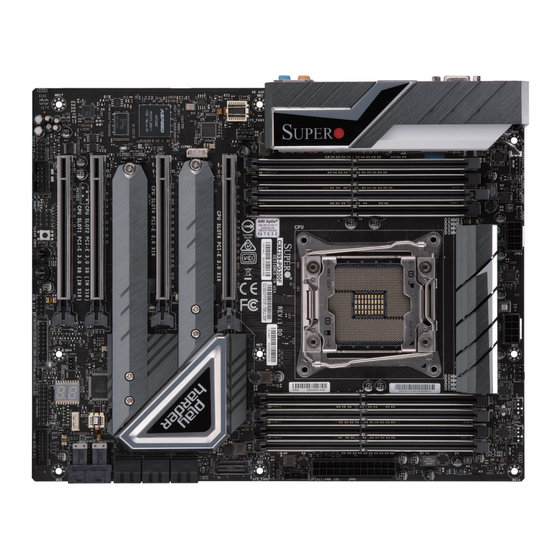
C9X299-PG300F
USER'S MANUAL
Revision 1.0a
Table of
Contents
Previous
Page
Next
Page
1
2
3
4
5
Advertisement
Table of Contents
Need help?
Do you have a question about the C9X299 and is the answer not in the manual?
Ask a question
Questions and answers
Related Manuals for Supermicro C9X299
Motherboard Supermicro C9X299-PG300 User Manual
(111 pages)
Motherboard Supermicro Supero C9X299-PG300 Quick Reference Manual
(26 pages)
Motherboard Supermicro C9Z390-PGW User Manual
(129 pages)
Motherboard Supermicro Supero C9Z390-PGW Quick Reference Manual
(34 pages)
Motherboard Supermicro Supero C9Z390-CG-IW Quick Reference Manual
(34 pages)
Motherboard Supermicro Supero C9X299-PG300F Quick Reference Manual
(28 pages)
Motherboard Supermicro C9Z490-PG User Manual
(142 pages)
Motherboard Supermicro SUPERO C9Z490-PG Quick Reference Manual
(28 pages)
Motherboard Supermicro Supero C9Z390-CGW Quick Reference Manual
(34 pages)
Motherboard Supermicro SuperO C9X299-PGF-L Quick Reference Manual
(11 pages)
Motherboard Supermicro C9X299-PGF-L User Manual
(129 pages)
Motherboard Supermicro C9Z790-CG User Manual
(139 pages)
Motherboard Supermicro C9Z890-MW User Manual
(163 pages)
Motherboard Supermicro C7Z270-CG Quick Reference Manual
(25 pages)
Motherboard Supermicro C7B250-CB-ML Quick Reference Manual
(25 pages)
Motherboard Supermicro C7Z170-M User Manual
(139 pages)
This manual is also suitable for:
Pg300f
Table of Contents
Print
Rename the bookmark
Delete bookmark?
Delete from my manuals?
Login
Sign In
OR
Sign in with Facebook
Sign in with Google
Upload manual
Upload from disk
Upload from URL


Need help?
Do you have a question about the C9X299 and is the answer not in the manual?
Questions and answers