Table of Contents
Advertisement
Advertisement
Table of Contents

Related Manuals for Supermicro C9Z390-PGW


Summary of Contents for Supermicro C9Z390-PGW
- Page 1 C9Z390-PGW USER’S MANUAL Revision 1.0...
- Page 2 This product, including software and documenta- tion, is the property of Supermicro and/or its licensors, and is supplied only under a license. Any use or reproduction of this product is not allowed, except as expressly permitted by the terms of said license.
- Page 3 This manual is written for system integrators, PC technicians and knowledgeable PC users. It provides information for the installation and use of the C9Z390-PGW motherboard. Manual Organization Chapter 1 describes the features, specifications and performance of the motherboard, and provides detailed information on the Intel Z390 chipset.
- Page 4 Supermicro C9Z390-PGW Motherboard User’s Manual Checklist Congratulations on purchasing your computer motherboard from an ac- knowledged leader in the industry. Supermicro boards are designed with the utmost attention to detail to provide you with the highest standards in quality and performance.
- Page 5 The following statements are industry-standard warnings, provided to warn the user of situations which have the potential for bodily injury. Should you have questions or experience difficulty, contact Supermicro's Technical Support department for assistance. Only certified technicians should attempt to install or configure components.
- Page 6 Supermicro C9Z390-PGW Motherboard User’s Manual ¡Advertencia! Existe peligro de explosión si la batería se reemplaza de manera incor- recta. Reemplazar la batería exclusivamente con el mismo tipo o el equivalente recomendado por el fabricante. Desechar las baterías gasta- das según las instrucciones del fabricante.
- Page 7 Standardized Warning Statements 製品の廃棄 この製品を廃棄処分する場合、 国の関係する全ての法律 ・ 条例に従い処理する必要が あります。 警告 本产品的废弃处理应根据所有国家的法律和规章进行。 警告 本產品的廢棄處理應根據所有國家的法律和規章進行。 Warnung Die Entsorgung dieses Produkts sollte gemäß allen Bestimmungen und Gesetzen des Landes erfolgen. ¡Advertencia! Al deshacerse por completo de este producto debe seguir todas las leyes y reglamentos nacionales.
- Page 8 Supermicro C9Z390-PGW Motherboard User’s Manual Contacting Supermicro Headquarters Address: Super Micro Computer, Inc. 980 Rock Ave. San Jose, CA 95131 U.S.A. Tel: +1 (408) 503-8000 Fax: +1 (408) 503-8008 Email: marketing@supermicro.com (General Information) support@supermicro.com (Technical Support) Website: www.supermicro.com Europe Address: Super Micro Computer B.V.
- Page 9 Contacting Supermicro Where to Find More Information For your system to work properly, please follow the links below to download all necessary drivers/utilities and the user's manual for your motherboard. Supermicro product manuals: http://www.supermicro.com/support/ manuals/ Product Drivers and utilities: https://www.supermicro.com/wftp/driver/...
-
Page 10: Table Of Contents
Supermicro C9Z390-PGW Motherboard User’s Manual Table of Contents Preface Chapter 1 Introduction Overview ................1-1 About this Motherboard ............1-1 Chipset Overview ..............1-1 Intel Z390 Chipset Features ............ 1-1 1-3 Motherboard Features ............... 1-2 Special Features ..............1-4 Recovery from AC Power Loss ..........1-4 PC Health Monitoring .............. - Page 11 Table of Contents Connectors/IO Ports ............. 2-14 Back I/O Panel ..............2-14 Universal Serial Bus (USB) ..........2-15 Back Panel High Definition Audio (HD Audio) ...... 2-17 ATX PS/2 Keyboard/Mouse Ports ........2-18 VESA® DisplayPort™ ............2-18 HDMI Port ............... 2-18 Ethernet Port ..............
- Page 12 Supermicro C9Z390-PGW Motherboard User’s Manual 2-9 Onboard Indicators ..............2-34 LAN LEDs ................ 2-34 Onboard Power LED (LED1) ..........2-34 Status Display (LED4) ............. 2-35 2-10 Hard Drive Connections ............2-36 SATA Connections (I-SATA0-I-SATA2) ......... 2-36 U.2 SSD Connectors ............2-36 Chapter 3 Troubleshooting Troubleshooting Procedures .............
-
Page 13: Chapter 1 Introduction
The C9Z390-PGW motherboard supports a single 8th Generation Intel® Core™ i9/i7/i5/i3 and 9000 series processor in an LGA 1151 (H4) socket. With the Intel® Z390 Express chipset built in, the C9Z390-PGW moth- erboard offers substantial system performance and storage capability for overclocking platforms in a sleek package. -
Page 14: Motherboard Features
Supermicro C9Z390-PGW Motherboard User’s Manual 1-3 Motherboard Features Single Intel® Core™ 8th Generation i9/i7/i5/i3 and 9000 series processor in an LGA 1151 (H4) type socket Four (4) slots support up to 64GB of unbuffered, non- Memory ECC, 2666/2400 MHz or 4000+MHz (OC) DDR4 memory... - Page 15 Chapter 1: Introduction Two (2) DisplayPort 1.2 One (1) HDMI 2.0 Port One (1) Serial Port header (COM1) Audio One (1) High Definition Audio 7.1 channel connector supported by Realtek ALC1220 on the back panel One (1) Front Panel Audio Header One (1) S/PDIF Out on the rear side of the chassis Super I/O Nuvoton NCT6792D-B...
-
Page 16: Special Features
Supermicro C9Z390-PGW Motherboard User’s Manual 1-4 Special Features Recovery from AC Power Loss Basic I/O System (BIOS) provides a setting for you to determine how the system will respond when AC power is lost and then restored to the system. You can choose for the system to remain powered off, (in which case you must press the power switch to turn it back on), or for it to automatically return to a power-on state. -
Page 17: System Resource Alert
Chapter 1: Introduction System Resource Alert This feature is available when the system is used with SuperDoctor 6 in the Windows and Linux operating systems. SuperDoctor is used to notify the user of certain system events. For example, you can also configure SuperDoctor to provide you with warnings when the system temperature, CPU temperatures, voltages and fan speeds go beyond predefined thresholds. -
Page 18: Power Supply
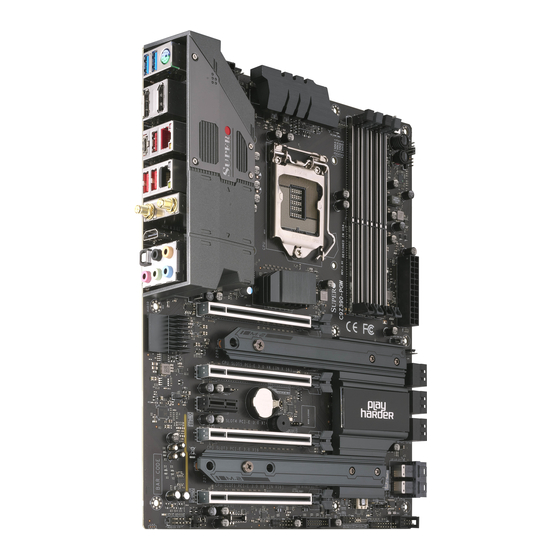
Supermicro C9Z390-PGW Motherboard User’s Manual 1-7 Power Supply As with all computer products, a stable power source is necessary for proper and reliable operation. It is even more important for processors that have high CPU clock rates. This motherboard accommodate a 24-pin ATX power supply. Although most power supplies generally meet the specifications required by the CPU, some are inadequate. - Page 19 Chapter 1: Introduction C9Z390-PGW Motherboard Image Note: All graphics shown in this manual were based upon the latest PCB Revision available at the time of publishing of the manual. The motherboard you've received may or may not look exactly the same...
- Page 20 Supermicro C9Z390-PGW Motherboard User’s Manual C9Z390-PGW Motherboard Layout MAC CODE MAC CODE DP1/2 HD AUDIO KB/MOUSE USB 2/3(3.0) HDMI LAN2 LAN1 SYS_FAN3 USB 4/5 (3.1) USB 6/7 (3.1) JI2C2 BAR CODE JI2C1/JI2C2 JPAC1:AUDIO MH10 WIFI+BT ON :ENABLE 1-2:ENABLE OFF:DISABLE 2-3:DISABLE...
- Page 21 Chapter 1: Introduction C9Z390-PGW Block Diagram PCIe3.0_x8 PCIe x16 SLOT #7 8.0GT/s PCIe3.0_x8 8.0GT/s SVID PCIe3.0_x8 IMVP8 PCIe x 8 (in x16) SLOT #5 PCIe3.0_x8 PCIe3.0_x16 8.0GT/s ASMedia Switch PLX8747 ASM1480 8.0GT/s 8.0GT/s INTEL LGA1151 DDR4 (CHA) DDI1 DIMMA0 Display Port...
- Page 22 Supermicro C9Z390-PGW Motherboard User’s Manual C9Z390-PGW Quick Reference MAC CODE MAC CODE DP1/2 HD AUDIO KB/MOUSE USB 2/3(3.0) HDMI LAN2 LAN1 SYS_FAN3 USB 4/5 (3.1) USB 6/7 (3.1) JI2C2 BAR CODE JI2C1/JI2C2 JPAC1:AUDIO MH10 WIFI+BT ON :ENABLE 1-2:ENABLE OFF:DISABLE 2-3:DISABLE...
- Page 23 Chapter 1: Introduction Connector Description 12V PUMP PWR1 12V 4-pin power connector for CPU pump of liquid cooling AUDIO FP Front Panel Audio Header Onboard Battery COM1 COM1 Header CPU SLOT1, 5 PCI Express x16 Slots (PCI-E 3.0 x8 link ) CPU SLOT3, 7 PCI Express x16 Slots (PCI-E 3.0 x16 link) PCH SLOT4...
- Page 24 Supermicro C9Z390-PGW Motherboard User’s Manual PCI-E M.2-M1,M2 PCI-E M.2 Connectors 1 and 2, small form factor devices and other portable devices for high speed NVMe SSDs (M1 shares link with U.2-1 port; M2 shares link with I-SATA4/5 port) System FAN 1,2,3/CPU...
-
Page 25: Chapter 2 Installation
Chapter 2: Installation Chapter 2 Installation 2-1 Installation Components and Tools Needed Screws Phillips-Head Screwdriver Intel LGA 1151 Processor DDR4 DIMMs PC Chassis Heatsink with Fan Power Supply Video Card (Optional) SATA/USB Optical Drive (Optional) SATA Hard Disk Drive... -
Page 26: Static-Sensitive Devices
Supermicro C9Z390-PGW Motherboard User’s Manual 2-2 Static-Sensitive Devices Electrostatic Discharge (ESD) can damage electronic com ponents. To avoid damaging your system board, it is important to handle it very carefully. The following measures are generally sufficient to protect your equipment from ESD. -
Page 27: Processor And Heatsink Installation
CPU socket cap is in place and none of the socket pins are bent; otherwise, contact your retailer immediately. Refer to the Supermicro website for updates on CPU support. Installing the LGA1151 Processor 1. Press the load lever to release the load plate, which covers the CPU socket, from its locking position. - Page 28 Supermicro C9Z390-PGW Motherboard User’s Manual 2. Gently lift the load lever to open the load plate. Remove the plas- tic cap. 3. Use your thumb and your index finger to hold the CPU at the North center edge and the South center edge of the CPU.
- Page 29 Chapter 2: Installation 5. Do not rub the CPU against the surface or against any pins of the socket to avoid damaging the CPU or the socket.) 6. With the CPU inside the socket, inspect the four corners of the CPU to make sure that the CPU is properly installed.
-
Page 30: Installing An Active Cpu Heatsink With Fan
Supermicro C9Z390-PGW Motherboard User’s Manual Installing an Active CPU Heatsink with Fan 1. Apply the proper amount of thermal grease to the heatsink. 2. Place the heatsink on top of the CPU so that the four mount- ing holes on the heatsink are aligned with those on the retention mechanism. -
Page 31: Removing An Active Cpu Heatsink With Fan
Chapter 2: Installation Removing an Active CPU Heatsink with Fan Warning: We do not recommend that the CPU or heatsink be removed. However, if you do need to remove the heatsink, please follow the instruc- tion below to uninstall the heatsink to avoid damaging the CPU or other components. -
Page 32: Installing Ddr4 Memory
Supermicro C9Z390-PGW Motherboard User’s Manual 2-4 Installing DDR4 Memory Note: Check the Supermicro website for recommended memory modules. Attention! Exercise extreme care when installing or removing DIMM modules to prevent any possible damage. DIMM Installation 1. Insert the desired number of... -
Page 33: Memory Support
SATA DOM PWR JSD1 BUTTON BUTTON JPW1 SYS_FAN2 The C9Z390-PGW supports up to 64GB of Unbuffered (UDIMM) non-ECC CLEAR CMOS DDR4 memory, up to 2666/2400MHz or 4000+MHz (OC) in four 288-pin I-SATA0 SYS_FAN1 I-SATA1 memory slots. Populating these DIMM modules with a pair of memory modules of the same type and size will result in interleaved memory, which will improve memory performance. -
Page 34: Memory Population Guidelines
Supermicro C9Z390-PGW Motherboard User’s Manual Memory Population Guidelines When installing memory modules, the DIMM slots should be populated in the following order: DIMMA2, DIMMB2, then DIMMA1, DIMMB1. • Always use DDR4 DIMM modules of the same size and speed. •... -
Page 35: Installation (Optional)
Chapter 2: Installation 2-4 M.2 Installation (optional) Two M.2 (M-key) connectors are supported by the C9Z390-PGW. M.2 devices are used for solid state storage and internal expansion. Follow the steps below in order to install an M.2 device. 1. Locate and remove the retaining screws on the M.2 heatsink. -
Page 36: Motherboard Installation
Supermicro C9Z390-PGW Motherboard User’s Manual 2-5 Motherboard Installation All motherboards have standard mounting holes to fit different types of chassis. Make sure that the locations of all the mounting holes for both motherboard and chassis match. Although a chassis may have both plas- tic and metal mounting fasteners, metal ones are highly recommended because they ground the motherboard to the chassis. -
Page 37: Installing The Motherboard
Chapter 2: Installation Installing the Motherboard 1. Install the I/O shield into the back of the chassis. 2. Locate the mounting holes on the motherboard. (See the previous page.) 3. Locate the matching mounting holes on the chassis. Align the mounting holes on the motherboard against the mounting holes on the chassis. -
Page 38: Connectors/Io Ports
Supermicro C9Z390-PGW Motherboard User’s Manual 2-6 Connectors/IO Ports The I/O ports are color coded in conformance with the industry standards. See the figure below for the colors and locations of the various I/O ports. Back I/O Panel MAC CODE MAC CODE... -
Page 39: Universal Serial Bus (Usb)
2260 JSTBY1 BIOS LICENSE PCIE M.2-M2 LED3 JL1: CHASSIS INTRUSION DIMMA1 PCIE M.2-M1 DIMMA2 JTPM1: TPM/PORT80 DIMMB1 C9Z390-PGW DIMMB2 REV:1.01A DESIGNED IN USA CPU LED DIMM LED VGA LED BOOT LED LED4 POWER RESET JSD1: SATA DOM PWR JSD1 BUTTON... - Page 40 Supermicro C9Z390-PGW Motherboard User’s Manual Front Panel USB (3.1 Gen 2 Type-C) Header #8 Pin Definitions Pin# Definition Pin# Definition Pin# Definition VBUS RX2+ TX1+ SBU1 RX2- TX1- SBU2 VBUS RX1+ TX2+ RX1- TX2- VBUS A. USB8 MAC CODE MAC CODE...
-
Page 41: Back Panel High Definition Audio (Hd Audio)
Chapter 2: Installation Back Panel High Definition Audio (HD Audio) This motherboard features a 7.1+2 Channel High Definition Audio (HDA) codec that provides 10 DAC channels. The HD Audio connections simul- taneously supports multiple-streaming 7.1 sound playback with 2 chan- nels of independent stereo output through the front panel stereo out for front, rear, center and subwoofer speakers. -
Page 42: Atx Ps/2 Keyboard/Mouse Ports
Supermicro C9Z390-PGW Motherboard User’s Manual ATX PS/2 Keyboard/Mouse Port The ATX PS/2 keyboard and PS/2 mouse are located above Back Panel USB Ports 2/3 on the motherboard. VESA® DisplayPort™ DisplayPort, develped by the VESA consortium, delivers digital display at a fast refresh rate. It can connect to virtually any display device using a DisplayPort adapter for devices such as VGA, DVI, or HDMI. -
Page 43: Front Control Panel
JF1 contains header pins for various buttons and indicators that are normally located on a control panel at the front of the chassis. These connectors are designed specifically for use with Supermicro chassis. See the figure below for the descriptions of the front control panel buttons and LED indicators. -
Page 44: Front Control Panel Pin Definitions
Supermicro C9Z390-PGW Motherboard User’s Manual Front Control Panel Pin Definitions Power LED Power LED Pin Definitions (JF1) The Power LED connection is located on Pin# Definition pins 15 and 16 of JF1. Refer to the table on the right for pin definitions. -
Page 45: Reset Button
Chapter 2: Installation Reset Button The Reset Button connection is located Reset Button Pin Definitions (JF1) on pins 3 and 4 of JF1. Attach it to a Pin# Definition hardware reset switch on the computer Reset Button case to reset the system. Refer to the Ground table on the right for pin definitions. -
Page 46: Connecting Cables
Supermicro C9Z390-PGW Motherboard User’s Manual 2-7 Connecting Cables This section provides brief descriptions and pinout definitions for onboard headers and connectors. Be sure to use the correct cable for each header or connector. ATX Main PWR & CPU PWR ATX Power 24-pin Connector Connectors (JPW1 &... -
Page 47: Fan Headers (Fan1-5)
2260 JSTBY1 BIOS LICENSE PCIE M.2-M2 LED3 JL1: CHASSIS INTRUSION DIMMA1 PCIE M.2-M1 DIMMA2 JTPM1: TPM/PORT80 DIMMB1 C9Z390-PGW DIMMB2 REV:1.01A DESIGNED IN USA CPU LED DIMM LED VGA LED BOOT LED LED4 POWER RESET JSD1: SATA DOM PWR JSD1 BUTTON... -
Page 48: Speaker (Jd1)
1-4 with a cable. Refer to the table on the right for pin definitions. Pump Power Header 12V_PUMP_PWR1 Pin Definitions The C9Z390-PGW has one +12V header Definition for optional CPU liquid cooling systems. Ground (Black) When using a liquid cooling system, at-... -
Page 49: Onboard Power Led (Jled1)
2260 JSTBY1 BIOS LICENSE PCIE M.2-M2 LED3 JL1: CHASSIS DIMMA1 INTRUSION PCIE M.2-M1 DIMMA2 JTPM1: TPM/PORT80 DIMMB1 C9Z390-PGW DIMMB2 REV:1.01A DESIGNED IN USA CPU LED DIMM LED VGA LED BOOT LED LED4 POWER RESET JSD1: SATA DOM PWR JSD1 BUTTON... -
Page 50: Dom Pwr Connector (Jsd1)
Supermicro C9Z390-PGW Motherboard User’s Manual DOM PWR Connector (JSD1) DOM PWR Pin Definitions The Disk-On-Module (DOM) power con- Pin# Definition nector, located at JSD1, provides 5V power to a solid state DOM storage Ground device connected to one of the SATA Ground ports. -
Page 51: Standby Power Header (Jstby1)
2260 JSTBY1 BIOS LICENSE PCIE M.2-M2 LED3 JL1: CHASSIS DIMMA1 INTRUSION PCIE M.2-M1 DIMMA2 JTPM1: TPM/PORT80 DIMMB1 C9Z390-PGW DIMMB2 REV:1.01A DESIGNED IN USA CPU LED DIMM LED VGA LED BOOT LED LED4 POWER RESET JSD1: SATA DOM PWR JSD1 BUTTON... -
Page 52: Front Panel Audio Header (Audio Fp)
Supermicro C9Z390-PGW Motherboard User’s Manual Front Panel Audio Header (AUDIO 10-in Audio Pin Definitions Pin# Signal A 10-pin Audio header is supported on Microphone_Left the motherboard. This header allows you Audio_Ground to connect the motherboard to a front Microphone_Right panel audio control panel, if needed. -
Page 53: Battery Connector
2260 JSTBY1 BIOS LICENSE PCIE M.2-M2 LED3 JL1: CHASSIS DIMMA1 INTRUSION PCIE M.2-M1 DIMMA2 JTPM1: TPM/PORT80 DIMMB1 C9Z390-PGW DIMMB2 REV:1.01A DESIGNED IN USA CPU LED DIMM LED VGA LED BOOT LED LED4 POWER RESET JSD1: SATA DOM PWR JSD1 BUTTON... -
Page 54: Jumper Settings
Supermicro C9Z390-PGW Motherboard User’s Manual 2-8 Jumper Settings Explanation of Jumpers To modify the operation of the mother- board, jumpers can be used to choose between optional settings. Jumpers create shorts between two pins to change the function of the connector. -
Page 55: Pci Slot Smb Enable (I C1/I C2)
2260 JSTBY1 BIOS LICENSE PCIE M.2-M2 LED3 JL1: CHASSIS DIMMA1 INTRUSION PCIE M.2-M1 DIMMA2 JTPM1: TPM/PORT80 DIMMB1 C9Z390-PGW DIMMB2 REV:1.01A DESIGNED IN USA CPU LED DIMM LED VGA LED BOOT LED LED4 POWER RESET JSD1: SATA DOM PWR JSD1 BUTTON... -
Page 56: Manufacturing Mode (Jpme2)
Supermicro C9Z390-PGW Motherboard User’s Manual Manufacturing Mode (JPME2) Manufacture Mode (JPME2) Close pins 2 and 3 of jumper JPME2 Jumper Settings to bypass SPI flash security and force Pin# Definition the system to operate in Manufacturing Normal (Default) Mode, allowing the user to flash the sys-... -
Page 57: Power Button
2260 JSTBY1 BIOS LICENSE PCIE M.2-M2 LED3 JL1: CHASSIS DIMMA1 INTRUSION PCIE M.2-M1 DIMMA2 JTPM1: TPM/PORT80 DIMMB1 C9Z390-PGW DIMMB2 REV:1.01A DESIGNED IN USA CPU LED DIMM LED VGA LED BOOT LED LED4 POWER RESET JSD1: SATA DOM PWR JSD1 BUTTON... -
Page 58: Onboard Indicators
Supermicro C9Z390-PGW Motherboard User’s Manual 2-9 Onboard Indicators LAN LEDs Two LAN ports are located on the I/O back Link Activity panel of the motherboard. This Ethernet LAN port has two LEDs (Light Emitting Diode). The yellow LED indicates activity, while the Link... -
Page 59: Status Display (Led4)
2260 JSTBY1 BIOS LICENSE PCIE M.2-M2 LED3 JL1: CHASSIS DIMMA1 INTRUSION PCIE M.2-M1 DIMMA2 JTPM1: TPM/PORT80 DIMMB1 C9Z390-PGW DIMMB2 REV:1.01A DESIGNED IN USA CPU LED DIMM LED VGA LED BOOT LED LED4 POWER RESET JSD1: SATA DOM PWR JSD1 BUTTON... -
Page 60: Hard Drive Connections
Supermicro C9Z390-PGW Motherboard User’s Manual 2-10 Hard Drive Connections SATA Connections (I-SATA0-I-SATA5) SATA 2.0/3.0 Connectors Pin Definitions Six Serial ATA (SATA) 3.0 connectors (I-SATA Pin# Signal 0-5) are supported on the board. These I-SA- Ground TA 3.0 ports are supported by the Intel Z390 SATA_TXP PCH chip (supports RAID 0, 1, 5, 10). -
Page 61: Chapter 3 Troubleshooting
Chapter 3: Troubleshooting Chapter 3 Troubleshooting 3-1 Troubleshooting Procedures Use the following procedures to troubleshoot your system. If you have followed all of the procedures below and still need assistance, refer to the ‘Technical Support Procedures’ and/or ‘Returning Merchandise for Service’ section(s) in this chapter. - Page 62 Supermicro C9Z390-PGW Motherboard User’s Manual No Video 1. If the power is on, but you have no video--in this case, you will need to remove all the add-on cards and cables first. 2. Use the speaker to determine if any beep codes exist. (Refer to Ap- pendix A for details on beep codes.)
-
Page 63: Technical Support Procedures
Before contacting Technical Support, please make sure that you have followed all the steps listed below. Also, note that as a motherboard manufacturer, Supermicro does not sell directly to end users, so it is best to first check with your distributor or reseller for troubleshooting services. -
Page 64: Frequently Asked Questions
Note: Always use the file named “ami.bat” to update the BIOS, and insert a space between "ami.bat" and the filename. The BIOS-ROM-filename will bear the motherboard name (i.e., C9Z390-PGW) and build version as the extension. For example, "C7Z390-PGW.115". When completed, your system will auto- matically reboot. -
Page 65: Battery Removal And Installation
Chapter 3: Troubleshooting Question: I think my BIOS is corrupted. How can I recover my BIOS? Answer: Please see Appendix C-BIOS Recovery for detailed instructions. 3-4 Battery Removal and Installation Battery Removal To remove the onboard battery, follow the steps below: 1. -
Page 66: Returning Motherboard For Service
Supermicro C9Z390-PGW Motherboard User’s Manual Battery Installation 1. To install an onboard battery, follow the steps 1 & 2 above and continue below: 2. Identify the battery's polarity. The positive (+) side should be fac- ing up. 3. Insert the battery into the battery holder and push it down until you hear a click to ensure that the battery is securely locked. -
Page 67: Chapter 4 Bios
BIOS 4-1 Introduction This chapter describes the AMI BIOS Setup Utility for the C9Z390-PGW. The ROM BIOS is stored in a Flash EEPROM and can be easily updated. This chapter describes the basic navigation of the AMI BIOS Setup Util- ity setup screens. - Page 68 Supermicro C9Z390-PGW Motherboard User’s Manual The AMI BIOS GUI Setup Utility uses a mouse pointer navigation system similar to standard graphical user interfaces. Hover and click an icon to select a section, click a down arrow to select from an options list.
-
Page 69: Ez Mode
Chapter 4: AMI BIOS 4-2 EZ Mode While in EZ Mode, the following information will be displayed: BIOS Version - The current BIOS version CPU Information - The model, speed, and voltage of installed CPU Memory Frequency - The frequency of installed memory System Temp - Displays CPU and PCH temperatures CPU Profile - Allows changing of the CPU profile by clicking the left or right arrows... - Page 70 Supermicro C9Z390-PGW Motherboard User’s Manual Intel Rapid Storage Technology - Allows for enabling Intel Rapid Storage Technology Fan Profile - Displays current fan speeds...
-
Page 71: Overclocking
Chapter 4: AMI BIOS 4-3 Overclocking CPU Overclocking CPU Profile This feature allows for preset CPU overclocking profiles to be selected. The options are Stable, Default, and Performance. Advanced CPU OC Setting This feature controls the CPU overclocking settings. The options are Manual, 4.3GHz, 4.4GHz, 4.5GHz, 4.6GHz, 4.7GHz, 4.8GHz, 4.9GHz, 5.0GHz, 5.1GHz, 5.2GHz, 5.3GHz, 5.4GHz, and 5.5GHz. - Page 72 Supermicro C9Z390-PGW Motherboard User’s Manual FCLK Frequency for Early Power On Select the FCLK frequency for early power on. The options are Normal (800MHz), 1GHz, 400MHz, and Auto. BCLK Aware Adaptive Voltage This feature enables BCLK Aware Adaptive Voltage, which helps avoid high voltage overrides by forcing pcode to be aware of the BCLK frequency when making calculations.
- Page 73 Chapter 4: AMI BIOS TVB Voltage Optimizations This feature enables thermal base voltage optimizations for processors that implement Intel Thermal Velocity Boost (TVB). The options are Disabled or Enabled. CPU feature Hyper-Threading This feature enables hyper-threading, which is a software method to control logical processor threads.
- Page 74 Supermicro C9Z390-PGW Motherboard User’s Manual Ring Ring Max OC Ratio Enter a value for the maximum overclock ratio for CPU Ring. The default is 0. Ring Down Bin This feature enables Ring Down Bin. If set to Enabled, the maximum ring ratio will not be observed.
- Page 75 Chapter 4: AMI BIOS Acoustic Noise Settings Acoustic Noise Mitigation This feature enables Acoustic Noise Mitigation, which mitigates acoustic noise on certain CPUs when they are in deep C-states. If set to Enabled, the following features may be configured: Pre-Wake Time Ramp Up Time Ramp Down Time Enter a value for the desired feature.
- Page 76 Supermicro C9Z390-PGW Motherboard User’s Manual PS Current Threshold1 Enter a value for PS Current Threshold1. The range is 0-512. The default is 80. PS Current Threshold2 Enter a value for PS Current Threshold2. The range is 0-512. The default is 20.
- Page 77 Chapter 4: AMI BIOS TDC Enable This feature enables TDC. The options are Disabled or Enabled. TDC Current Limit Enter a value for the TDC Current Limit, with each whole number equating to 1/8A (i.e. 1000 = 125A). The range is 0-32767. The default is 800.
- Page 78 Supermicro C9Z390-PGW Motherboard User’s Manual PS3 Enable This feature enables PS3. The options are Disabled or Enabled. PS4 Enable This feature enables PS4. The options are Disabled or Enabled. IMON Slope Enter a value for IMON Slope. The range is 0-200. The default is 0.
- Page 79 Chapter 4: AMI BIOS TDC Lock This feature enables TDC Lock. The options are Disabled or Enabled. Intersil VR Command This feature enables Intersil VR Command to fix VR C-state issues. The options are Disabled, Send for IA/GT rails, and Send for IA/ GT/SA rails.
- Page 80 Supermicro C9Z390-PGW Motherboard User’s Manual Memory Ratio This feature controls the memory ratio. The memory frequency is equal to the memory ratio times the ference clock. Memory Voltage Enter a value for the memory voltage override. The default is 1200.
- Page 81 Chapter 4: AMI BIOS ODT RTT WR(CHA) This feature controls ODT RTT WR(CHA). The options are Auto, 0, 80, 120, 240, and 255. ODT RTT PARK(CHA) This feature controls ODT RTT PARK(CHA). The options are Auto, 0, 34, 40, 48, 60, 80, 120, and 240. ODT RTT NOM(CHA) This feature controls ODT RTT NOM(CHA).
- Page 82 Supermicro C9Z390-PGW Motherboard User’s Manual Graphics OverClocking GT OverClocking Frequency Enter a value for the overclocked RP0 frequency (in multiples of 50 MHz) in the GT domain. The default is 0. GT Voltage Mode This feature controls the voltage mode in the GT domain. The options are Adaptive or Override.
- Page 83 Chapter 4: AMI BIOS GTU Voltage Offset Enter a value for the offset voltage (in mV) that will be applied to the GT domain. The default is 0. Offset Prefix Use this feature to set the prefix value as a positive (+) or a negative (-).
- Page 84 Supermicro C9Z390-PGW Motherboard User’s Manual PCH Voltage Enter a value for the PCH voltage override. The default is 1010. PCH 1.8 Voltage Enter a value for the PCH 1.8 voltage override. The default is 1800. CPU PLL Voltage Enter a value for the CPU PLL voltage override. The default is 1200.
- Page 85 Chapter 4: AMI BIOS System Agent PLL Voltage Offset Enter a value for the System Agent PLL voltage offset, with each whole number equating to 17.5 mV. The range is 0-63. The default is 0. Memory Controller PLL Voltage Offset Enter a value for the Memory Controller PLL voltage offset, with each whole number equating to 17.5 mV.
-
Page 86: Cpu
Supermicro C9Z390-PGW Motherboard User’s Manual 4-4 CPU The following information is displayed in this section: • Type - the brand, model name, model number of the CPU, and its rated clock speed • Speed - the detected CPU speed •... - Page 87 Chapter 4: AMI BIOS CPU Configuration The following CPU information will be displayed: • Type - the brand, model name, model number of the CPU, and its rated clock speed • ID - the unique CPU ID • Speed - the detected CPU speed •...
- Page 88 Supermicro C9Z390-PGW Motherboard User’s Manual Adjacent Cache Line Prefetch (Available when supported by the CPU) Select Enabled for the CPU to prefetch both cache lines for 128 bytes as comprised. Select Disabled for the CPU to prefetch both cache lines for 64 bytes.
- Page 89 Chapter 4: AMI BIOS TXT support (when supported by the CPU) Intel TXT (Trusted Execution Technology) helps protect against software-based attacks and ensures protection, confidentiality and integrity of data stored or created on the system. The options are Disabled or Enabled. Reset AUX Content (when supported by the CPU) Use this feature to reset the TPM Auxiliary content.
- Page 90 Supermicro C9Z390-PGW Motherboard User’s Manual Enhanced C-states This feature enables Enhanced C1 Power State to lower system energy consumption while all cores are in C-State. The options are Disabled or Enabled. C-State Auto Demotion When this feature is enabled, the CPU will conditionally demote C- State based on un-cored auto-demote information.
- Page 91 Chapter 4: AMI BIOS GT - Power Management Control RC6 (Render Standby) Use this feature enable Render Standby support. The options are Disabled or Enabled. Maximum GT Frequency This feature defines the Maximum GT Frequency. Choose between 100MHz (RPN) and 1200MHz (RP0). Any value beyond this range will be clipped to its min/max supported by the CPU.
-
Page 92: Memory
Supermicro C9Z390-PGW Motherboard User’s Manual 4-5 Memory The following information is displayed: • Memory RC Version • Memory Frequency • Memory Timings (tCL-tRCD-tRP-tRAS) • DIMM#A1 ~ DIMM#B2 Maximum Memory Frequency This feature selects the type/speed of the memory installed. The options are 1333, 1600, 1867, 2133, 2400, and 2667. - Page 93 Chapter 4: AMI BIOS Force Single Rank When enabled, only Rank0 will be use in each DIMM. The settings are Disabled or Enabled. Memory Remap PCI memory resources will overlap with the total physical memory if 4GB of memory (or above) is installed on the motherboard. When this oc- curs, Enable this function to reallocate the overlapped physical memory to a location above the total physical memory to resolve the memory overlapping situation.
-
Page 94: Advanced
Supermicro C9Z390-PGW Motherboard User’s Manual 4-6 Advanced Setup Mode This feature sets the default mode to start in after entering BIOS. The options are EZ Mode or Advanced Mode. Boot Feature Fast Boot This feature enables the system to boot with a minimal set of required devices to launch. - Page 95 Chapter 4: AMI BIOS Wait For "F1" If Error Use this feature to force the system to wait until the "F1" key is pressed if an error occurs. The options are Disabled or Enabled. Re-try Boot If this feature is enabled, the BIOS will automatically reboot the system from a specified boot device after its initial boot failure.
- Page 96 Supermicro C9Z390-PGW Motherboard User’s Manual RGB Led Control This feature enables RGB LED controls. The options are Disabled or Enabled. NCT6792D Super IO Configuration Super IO Chip - NCT6792D Serial Port 1 Configuration Serial Port This feature will Enable or Disable Serial Port 1 (COM1). Check the box to enable Serial Port 1.
- Page 97 Chapter 4: AMI BIOS COM1 Bits per second Use this feature to set the transmission speed for a serial port used in Console Redirection. Make sure that the same speed is used in the host computer and the client computer. A lower transmission speed may be required for long and busy lines.
- Page 98 Supermicro C9Z390-PGW Motherboard User’s Manual COM1 Resolution 100x31 Select Enabled for extended-terminal resolution support. The options are Disabled or Enabled. COM1 Legacy OS Redirection Resolution Use this feature to select the number of rows and columns used in Console Redirection for legacy OS support. The options are 80x24 or 80x25.
- Page 99 Chapter 4: AMI BIOS EMS Bits per second This feature sets the transmission speed for a serial port used in Con- sole Redirection. Make sure that the same speed is used in both host computer and the client computer. A lower transmission speed may be required for long and busy lines.
- Page 100 Supermicro C9Z390-PGW Motherboard User’s Manual GNA Device (B0:D8:F0) This feature enables the SA GNA device. The options are Disabled or Enabled. X2APIC Opt Out This feature enables X2APIC Opt Out. The options are Disabled or Enabled. Graphics Configuration Graphics Turbo IMON Current Enter a value for the graphics turbo IMON current.
- Page 101 Chapter 4: AMI BIOS Primary PCIE This feature controls the primary PCIE device. The options are Auto or PCH SLOT4 PCI-E 3.0 X1. Internal Graphics This feature enables internal graphics support, based on the setup op- tions. The options are Auto, Disabled, and Enabled. GTT Size This feature controls the memory allocation size for the graphics transla- tion table (GTT).
- Page 102 Supermicro C9Z390-PGW Motherboard User’s Manual Graphics Clock Frequency This feature controls the graphics clock frequency. Select the highest clock frequency supported by the platform. The options are 337.5 Mhz, 450 Mhz, 540 Mhz, and 675 Mhz. Skip CD Clock Init in S3 resume This feature enables skipping the full CD clock initialization.
- Page 103 Chapter 4: AMI BIOS M.2-M2 L1 Substates This features configures the L1 substate for M.2-M2. The options are Disabled, L1.1, and L1.1 & L1.2. M.2-M1 ASPM This feature configures the ASPM (Active State Power Management) set- tings for M.2-M1. The options are Disabled, L0s, L1, L0sL1, and Auto. M.2-M1 L1 Substates This features configures the L1 substate for M.2-M1.
- Page 104 Supermicro C9Z390-PGW Motherboard User’s Manual Serial ATA Port0~5 Hot Plug This feature designates the port specified for hot plugging. Set this item to Enabled for hot-plugging support, which will allow the user to replace a SATA disk drive without shutting down the system. The options are Disabled or Enabled.
- Page 105 Chapter 4: AMI BIOS USB Mass Storage Driver Support This feature enables USB mass storage driver support. The options are Disabled or Enabled. Port 60/64 Emulation This feature enables I/O port 60h/64h emulation for legacy USB keyboard support on non-USB aware operating systems. The options are Disabled or Enabled.
- Page 106 Supermicro C9Z390-PGW Motherboard User’s Manual Onboard LAN2 SUPPORT Use this feature to enable the onboard LAN2 device. The options are Disabled or Enabled. Onboard LAN Option ROM Type Use this feature to select the type of option ROM installed. The options are EFI or Legacy.
- Page 107 Chapter 4: AMI BIOS Ipv6 HTTP Support Use this feature to enable IPv6 HTTP boot support. The options are Disabled or Enabled. IPSEC Certificate This feature enables IPSEC certificate for Ikev. The options are Disabled or Enabled. PXE boot wait time Enter a value for the wait time (in seconds) to press the ESC key to abort the PXE boot.
- Page 108 Supermicro C9Z390-PGW Motherboard User’s Manual Platform Hierarchy This feature enables Platform Hierarchy. The options are Disabled or Enabled. Storage Hierarchy This feature enables Storage Hierarchy. The options are Disabled or Enabled. Endorsement Hierarchy This feature enables Endorsement Hierarchy. The options are Disabled or Enabled.
- Page 109 Chapter 4: AMI BIOS Secure Boot The following information will be displayed: • System Mode • Secure Boot Attempt Secure Boot Select Enabled for Secure Boot flow control. This feature is available when the platform key (PK) is pre-registered, the platform operates in the user mode, and CSM is disabled in the Setup utility.
- Page 110 Supermicro C9Z390-PGW Motherboard User’s Manual Restore DB defaults This feature restores DB variables to their factory defaults. Click Yes or No. Platform Key (PK) This item uploads and installs a secure Platform Key. You may insert a factory default key or load from a file. When prompted, select "Yes"...
- Page 111 Chapter 4: AMI BIOS Input the description Enter a name for Http boot option. Boot URI Enter a value for a new Boot Option to be created according to this Boot URI. The default is 0. Network Configuration This submenu becomes configurable when the "Onboard LAN Option ROM Type"...
- Page 112 Supermicro C9Z390-PGW Motherboard User’s Manual NIC Configuration Link Speed This feature controls the port speed used for the selected boot protocol. The options are Auto Negotiated, 10 Mbps Half, 10 Mbps Full, 100 Mbps Half, and 100 Mbps Full. Wake On LAN This feature enables the system to be powered on using an in-band packet.
-
Page 113: H/W Monitor
Chapter 4: AMI BIOS 4-7 H/W Monitor System Temperature The following items will be displayed: • CPU Temperature - the CPU temperature detected by PECI • System Temperature - the system internal temperature • Peripheral Temperature - the detected peripheral device tempera- ture •... - Page 114 Supermicro C9Z390-PGW Motherboard User’s Manual • 5VCC • VDIMM • VCPU_IO • PCH 1.0V • 3.3V_DL • • 3.3VCC • VBAT • VCPU_STPLL Fan Control Fan Speed Control Mode This feature allows the user to decide how the system controls the speeds of the onboard fans.
-
Page 115: Save & Exit
Chapter 4: AMI BIOS 4-8 Save & Exit Boot mode select Use this item to select the type of device to be used for system boot. The options are Legacy, UEFI, and Dual. FIXED BOOT ORDER Priorities This option prioritizes the order of bootable devices from which the system will boot. - Page 116 Supermicro C9Z390-PGW Motherboard User’s Manual Delete Boot Option Removes an EFI boot option from the boot order. UEFI Application Boot Priorities Specifies the Boot Application Priority sequence from available UEFI Ap- plications. NETWORK Drive BBS Priorities Specifies the Boot Device Priority sequence from available Network Drives.
-
Page 117: Bios Update
Chapter 4: AMI BIOS 4-9 BIOS Update The following items will be displayed: BIOS Version BIOS Tag Date Time Start Update Use this utility to prepare BIOS Update with ME. 1. Click "Start Update" enter the SuperFlash utility. 2. At the prompt, select "Yes" to reboot and configure the system to Flash mode. - Page 118 Supermicro C9Z390-PGW Motherboard User’s Manual 6. Select "Start Flash" to flash the BIOS. A pop-up message will ap- pear to show the progress of the BIOS flash. 7. If the flash is successful, a pop-up message will indicate the result.
-
Page 119: Appendix A Bios Error Beep Codes
Appendix A: POST Error Beep Codes Appendix A BIOS Error Beep Codes During the POST (Power-On Self-Test) routines, which are performed each time the system is powered on, errors may occur. Non-fatal errors are those which, in most cases, allow the system to continue with bootup. - Page 120 Supermicro C9Z390-PGW Motherboard User’s Manual Notes...
-
Page 121: Appendix B Software Installation Instructions
(Note: To install the Windows Operating System, please refer to the instructions posted on our website at http://www.supermicro.com/support/manuals/.) Driver/Tool Installation Display Screen Note 1. Click the icons showing a hand writing on the paper to view the readme files for each item. -
Page 122: Configuring Superdoctor ® 5
Supermicro C9Z390-PGW Motherboard User’s Manual ® B-2 Configuring SuperDoctor The SuperDoctor 5 program is a Web-based management tool that supports remote management capability. It includes Remote and Local Management tools. The local management tool is called the SD 5 Client. - Page 123 Appendix B: Software Installation Instructions Note: The SuperDoctor 5 software and manual may be downloaded from our Website at: https://www.supermicro.com/Products/nfo/SMS_SD5.cfm...
- Page 124 Supermicro C9Z390-PGW Motherboard User’s Manual Notes...
-
Page 125: Appendix C Uefi Bios Recovery Instructions
Attention! Do not upgrade the BIOS unless your system has a BIOS-related issue. Flashing the wrong BIOS can cause irreparable damage to the system. In no event shall Supermicro be liable for direct, indirect, special, incidental, or consequential damages aris- ing from a BIOS update. -
Page 126: To Recover The Main Bios Block Using A Usb-Attached Device
Supermicro C7Z390-PGW Motherboard User’s Manual C-3 To Recover the Main BIOS Block Using a USB- Attached Device This feature allows the user to recover a BIOS image using a USB- attached device without additional utilities used. A USB flash device such as a USB Flash Drive, or a USB CD/DVD ROM/RW device can be used for this purpose. - Page 127 Appendix C: UEFI BIOS Recovery 4. After locating the new BIOS binary image, the system will enter the BIOS Recovery menu as shown below. Note: At this point, you may decide if you want to start with BIOS Recovery. If you decide to proceed with BIOS Recovery, follow the procedures below.
- Page 128 Supermicro C7Z390-PGW Motherboard User’s Manual Notes...
- Page 129 (Disclaimer Continued) The products sold by Supermicro are not intended for and will not be used in life support systems, medical equipment, nuclear facilities or systems, aircraft, aircraft devices, aircraft/emergency com- munication devices or other critical systems whose failure to perform be reasonably expected to result in significant injury or loss of life or catastrophic property damage.
Need help?
Do you have a question about the C9Z390-PGW and is the answer not in the manual?
Questions and answers