
Subscribe to Our Youtube Channel
Related Manuals for Pavone Systems DAT11


Summary of Contents for Pavone Systems DAT11
- Page 1 TECHNICAL MANUAL DAT11 Serial and analog weighing Indicator/Trasnmitter Software version P33301 PAVONESYSTEMS...
- Page 2 Page II...
-
Page 3: Table Of Contents
TABLE OF CONTENTS WARNINGS ....................Page INTRODUCTION ................... Page TECHNICAL FEATURES ................... Page INSTALLATION ....................Page FRONT PANEL ....................Page 13 USING THE KEYBOARD ................. Page 14 DISPLAY INDICATIONS ................... Page 17 OPERATING FUNCTIONS ................Page 18 SET-UP ......................Page 22 DIAGRAM OF THE MENU ................ -
Page 4: Warnings
WARNINGS READ this manual BEFORE operating or servicing on the instrument. FOLLOW these instructions carefully. SAVE this manual for future use. CAUTION The installation and maintenance of this instrument must be allowed to qualified personnel only. Be careful when you perform inspections, testing and adjustment with the instrument swithced on. -
Page 5: Introduction
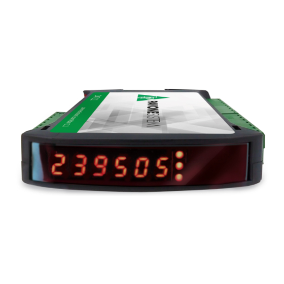
INTRODUCTION The DAT11 is a weight transmitter to be matched to the load cells to detect the weight in every situation. The module is easy to install and can be mounted on 35 mm DIN rail. The display allows easy reading of the weight, the configuration parameters and errors. -
Page 6: Technical Features
0 ÷ 4 decimal places Calibration of zero and full scale From the buttons. Check of load cell cable interruption Always present Logic outputs (DAT11/A) 2 relay outputs with No contact(0,1A, 24 Vdc/Vca) Logic Inputs (DAT11/A) No. 2 opto-isolated Serial ports... -
Page 7: Installation
The DAT11 consists of a motherboard, to which are added the options available, accommodated in a plastic enclosure for DIN rail 35mm. The DAT11 should not be immersed in water, subjected to jets of water and cleaned or wa- shed with solvents. - Page 8 LOAD CELL CONNECTIONS The cable of the load cell (or load cells) should not be channeled with other cables, but has to follow its own path. The instrument can be connected up to maximum 4 load cells of 350 ohm in parallel. The supply voltage of the load cells is 4 Vdc and is protected by temporary short circuit.
- Page 9 15 meters (EIA RS-232-C), beyond which you should take the optional RS485 interface. RS485: The RS485 serial port (2-wire) is only present in the model DAT11/ RS485. Rx/Tx+ To achieve the serial connection use a suitable shielded cable and...
- Page 10 DAT11/A TRANSMITTER ANALOG OUTPUT The instrument provides an analog output in current and voltage. Analog voltage output: range from -10 to +10 V or -5 to +5 volts, 10K ohm minimum load. A GND V OUT+ Analog current output: range from 0 to 20 mA or 4 to 20 mA. The I OUT + maximum load is 300Ω.
- Page 11 To connect to the MASTER, use a standard twisted pair Ethernet DESCRIPTION cable with RJ45 connector. The RJ45 Ethernet connection cable has a variable maximum length, depending on the type of cable. A common Cat5 shielded cable can have a maximum length of about 180 m. •...
- Page 12 IN and OUT. Putting more DAT11 instruments in series, the MASTER will be con- nected to the IN connector of the first DAT11, whose OUT connector will be connected to the IN connector of the next etc ...
- Page 13 PROFIBUS DP CONNECTION Signal Description B line +RxD/+TxD, level RS485 Request to send Ground (isolated) + 5V Bus Output +5V termination (isolated) A line -RxD/-TxD, level RS485 Housing Cable shield Internally connected to protective earth according to Profibus specification For connection to the Profibus Master, use a standard Profibus cable. The typical impedance of the cable should be between 100 and 130 Ohms (f>...
- Page 14 CANOPEN CONNECTION Signal Description CAN_L CAN low bus line CAN_GND CAN_H CAN high bus line CANopen is an higher-layer communication protocols based on a CAN seria bus system. For the connection using a cable with a twisted pair differential and common return in accordance with ISO 11898.
-
Page 15: Front Panel
FRONT PANEL The DAT11 transmitter has a front door that protects the 6 digits display, the 2 status LEDs and the three front keys. In operating mode the display shows the weight and the LEDs indicate the status of weight (net-gross). -
Page 16: Using The Keyboard
USING THE KEYBOARD The instrument is programmed and controlled through the 3 keys keyboard, with the following functions SYMBOL DESCRIPTION Short press on the single key. Long press on a single key. OPERATION FUNCTIONS DURING WEIGHT DISPLAY Access to the set points value programming menu Display selection (gross weight, net weight). - Page 17 FUNCTION DURING SETTING OF THE NUMERICAL VALUES It increases the value of the selected digit. It decreases the value of the selected digit. It selects the most-right digit. It resets all the digits. It ends composition and saves the value. It exits without saving the changes.
- Page 18 EXITING THE CONFIGURATION MENU Press the key to return to the main menu. Press the key again “StorE?”is displayed. Keep the key pressed until the message “sEtUP” appears. Press the key. to return to the weight display. Page 16...
-
Page 19: Display Indications
DISPLAY INFO When the instrument is switched ON, a display test is run followed by the identifica- P33301 tion code and then the version of the software, in that order. These codes are to be cited when requesting assistance When is not in progress a programming procedure, the display shows the weight measured in kilograms. Under certain conditions, the following messages are reported: NOTIFICATION OF ERRORS In operating mode, the following error codes may appear on the display. -
Page 20: Operating Functions
OPERATING FUNCTIONS Once calibrated, the display shows the current weight whenever it is switched on. The following are the possible operations that can be carried out from the keyboard when viewing the weight of the instrument. OPERATION FUNCTION Display of Gross Weight to Net Weight. Display of the peak. - Page 21 When the instrument is in the “Gross” operating mode (“NET” LED off) the DOWN key , hold down for few seconds, performs the gross weight resetting function. ZERO SETTING The reset command of the gross weight is used to correct for small zero shifts of the weighing system during normal operation.
- Page 22 PEAK FUNCTION The instrument continuously memorises the peak value of the gross weight. This function is available only if the peak calculation function is enabled via the corresponding parameter in the set-up menu of the instrument. The peak display is shown by the letter P on the left of the display. The peak value is detectedat the same frequency of acquisition of the weight (see table on filters).
- Page 23 PROGRAMMING THE WEIGHT SET-POINTS The set-points are compared with the weight to drive the relative logic output. The comparison criterionis defined during set-up of the logic inputs/outputs (see the relevant section). To access the Set points setting, press the SET key while viewing the weight MENU MESSAGE DESCRIPTION...
- Page 24 With the first field installation some parameters have to be changed in order to obtain a correct indica- tion of the displayed weight (Theoretical calibration). This may be required when you first purchase the DAT11. The settings of the setup menu can be changed using the keys on the front or the “OPTIMATION”utility software provided.
- Page 25 FUNCTION WHILE SETTING SUGGESTED VALUES It selects the next value. It selects the previous value. It confirms and stores the displayed value. It exits without saving the changes. CHANGING AND ENTERING THE PARAMETERS: The procedure for accessing the menu depends on the operating mode selected: FREE or METRIC. MENU ACCESS IN FREE OPERATION MODE.
-
Page 26: Setup
The second menu is that of tEst concerning procedures for functional testing of the instrument. The third is that of SEtup which allows you to program the parameters which determine the operation of the instrument To access the setup menu, press the PRG key and then the SET key and hold them down simultaneously for 3 seconds or press and hold the PRG key for at least 6 seconds . - Page 27 TEST MENU MENU MESSAGE NAME DESCRIPTION TYPE Display of the signal in mV/V in input to the Cell signal Vis. S1GnAL instrument Display of the weight with a resolution 10 Resolution x10 Vis. H1 rES. times greater than that set Display of the supply voltage measured by Power supply voltage Vis.
-
Page 28: Diagram Of The Menu
DIAGRAM OF THE MENU Page 26... -
Page 29: Configuration Parameters
CONFIGURATION PARAMETERS All the parameters that can be set are described in the following pages. At the end of each parameter description, where present, the fieldbus address corresponding to the parameter is shown. If the pa- rameter is the selectable type, the value to be entered in the register for the desired selection is shown between “[ ]”. - Page 30 SySt. F S CAPACITY OF THE WEIGHING SYSTEM [1301-1302] Programming the useful capacity (net) of the weighing system. Values: from 0 to Load Cell Capacity Default: 0 dEAd L. FIXED TARE OF WEIGHING SYSTEM [1106-1107] Programming the fixed tare value of the weighing system Values: from 0 to Capacity Value Default: 00000 CAL.
- Page 31 CONFIGURATION/CALIBRATION EXAMPLE Set the parameters listed above to perform theoretical calibration of the Full Scale of the DAT 11. This procedure must be completed with calibration of the zero-point as described later on. The procedure ensures good precision of the system (maximum error <1% FS) when there are no mechanical problems. When you change the rESOLU selection, calibration of the full-scale is automatically recalculated.
- Page 32 CALIBRATION OF SAMPLE WEIGHTS The calibration procedure described below should be carried out using sample weights and/or a sample product pre-weighed on a weighing system. Before proceeding with calibration of the full scale, always perform zero calibration. During the calibration phase, the weight is shown on the display in alternation with the text CAL. WARNING: Switching off the instrument without exiting the set-up menu cancels any changes made during the programming process.
- Page 33 The linearisation points are automatically reset by any change of the theoretical calibration data or if a full-scale calibration is performed. TABLE CALIBRATION It allows you to manually program up to five calibration points, in addition to zero. The values corre- sponding to those resulting from the linearisation procedure with sample weights.
-
Page 34: Analog Parameters
ANALOG - ANALOG OUTPUT PARAMETERS (OPTIONAL) rAnGE. . ANALOG OUTPUT RANGE [1506] Select the analogue output range. Selectable setting: 0÷10 Vdc [0] 0÷5 Vdc [1] 4÷20 mA [2] 0÷20 mA [3] Default: 0÷10 Vdc NodE. . ANALOG OUTPUT OPERATION MODE [1505] Selection of the value to be associated to the analogue output, corresponding to the net weight, gross weight or peak value. - Page 35 FS. A dJ. . FULL SCALE OFFSET REGULATION Measure the analogue output value with a multimeter to perform the full scale (FS) calibration. Use the keys to regulate the analogue output. Hold the key for a quick change. Press key to go back to the ANALOG menu.
-
Page 36: Serial Parameters
SERIAL COMMUNICATIONS PARAMETERS This menu makes it possible to configure the COM1 and COM2 serial ports and the communication param- eters. The instrument has two independent serial ports: COM1 always with interface RS232 ; COM2 can be fitted with either of the following interfaces: RS485, ETHERCAT, ETHERNET, ETHERNET IP, PROFINET. - Page 37 C1baud. COM1 BAUD RATE Defines the baud rate of serial port RS232. The value must be set at the same value as PC/PLC or remote display. Values that can be selected: 1200 2400 4800 9600 19200 38400 57600 115200 Default: 9600 C1ForN COM1 PROTOCOL Type of frame.
- Page 38 COM 2 PARAMETERS WHEN PRESENT RS485 C2 Nod. . COM2 OUTPUT MODE Selecting the value transmitted on output RS 485. Values that can be selected: GroSS PEAk Default: nEt C2Prot. . . COM2 PROTOCOL It defines how to use the RS485 serial port: Values that can be selected: None: Serial communication OFF Contin: Continuous transmission of the weight string.
- Page 39 C2ForN COM2 PROTOCOL Type of frame. For the SLAVE or MODBUS protocol you cannot select 7-bit data format (E-7-1 e O-7-1): Values that can be selected: n-8-1 n-8-2 E-7-2 E-8-1 o-7-2 o-8-1 Default: n-8-1 C2Addr. COM2 ADDRESS Communication address of the serial port: Values from 1 to 32 Default: 1 Page 37...
- Page 40 COM 2 PARAMETERS WHEN PROFINET / ETHERCAT IS PRESENT En. F buS. FIELDBUS ENABLING Enabling PROFINET / ETHERCAT fieldbus, if OFF error messages concerning FIELDBUS communication are never displayed: Values that can be selected: Default: OFF InP. r EG. . INPUT AREA DIMENSION Input area dimension for fieldbus (value expressed in Bytes).
- Page 41 PARAMETERS COM 2 WHEN ETHERNET IP IS PRESENT En. F buS. FIELDBUS ENABLING Enabling ETHERNET IP fieldbus, if OFF error messages concerning Fieldbus communication are never displayed: Values that can be selected: Default: OFF IP ADDRESS ETHERNET IP protocol address Values from 0.0.0.0 to 255.255.255.255 Default: 0.0.0.0 SubnEt...
- Page 42 COM 2 PARAMETERS WHEN ETHERNET IS PRESENT IP ADDRESS ETHERNET protocol IP address Values from 0.0.0.0 to 255.255.255.255 Default: 192.168.0.201 SubnEt SUBNET MASK ETHERNET protocol Subnet Mask. Values from 0.0.0.0 to 255.255.255.255 Default: 255.255.255.0 GatE GATEWAY ETHERNET protocol gateway. Values from 0.0.0.0 to 255.255.255.255 Default: 192.168.0.1 Port PORT...
- Page 43 Eth. P ro. . ETHERNET COMMUNICATION PROTOCOL Selecting communication type for Ethernet protocol. Values that can be selected: None: Serial communication OFF Contin: Continuous transmission of the weight string. It can be used, for example, to drive a weight repeater. See details in the relevant section. on deM: When the Operator presses the relative button on the front or uses Input 2, a weight string is sent.
- Page 44 COM 2 PARAMETERS WHEN PROFIBUS DP IS PRESENT En. F buS. FIELDBUS ENABLING Enabling PROFIBUS DP fieldbus, if OFF error messages concerning Fieldbus communication are never displayed: Values that can be selected: Default: OFF Addr. P r PROFIBUS ADDRESS Programming the address used in the PROFIBUS protocol. Values: from 0 to 126 Default: 01 InP.
- Page 45 COM 2 PARAMETERS WHEN CANOPEN IS PRESENT En. F buS. FIELDBUS ENABLING Enabling CANOPEN fieldbus, if OFF error messages concerning Fieldbus communication are never displayed: Values that can be selected: Default: OFF Addr. C o CANOPEN ADDRESS Programming the address used in the CANOPEN protocol. Values: from 0 to 126 Default: 1 Baud.
-
Page 46: Input/Output Parameters
INPUT/OUTPUT PARAMETERS FUn. 1 n. 1 INPUT 1 FUNCTION Selecting the function associated with input 1. [1401] Values that can be selected: Zero: It calibrates to zero. [0] Tare: It executes the automatic tare. [1] Del.Tar: It cancels the tare. [2] Peak: Reset of the peal function. - Page 47 Select if positive or negative values have to be compared. [1405] PoSIt.. The output is operative with positive weight. [0] nEGAt. The output is operative with negative weight. [1] ALL: The output is operative both with positive and negative weight. [2] Default: PoSIt Select whether only stable weight values are to be compared or also unstable: [1406] norMAL...
- Page 48 Selecting the output status if normally open or closed: [1411] n. oPEn. Relay 2 is normally open. [0] n.CLoSE Relay 2 is normally closed. [1] Defaul: n. oPEn. Select if positive or negative values have to be compared. [1412] PoSIt.. The output is operative with positive weight.
-
Page 49: Weighing Parameters
WEIGHING PARAMETERS The parameters in this menu permit adjustment of the times for acquisition and updating of the display and manual or automatic resetting by the transmitter. INSTRUMENT OPERATION Selecting the operation of the instrument. In case of a change from FREE operation to METRIC opera- tion, to confirm the setting authentication is required through the password of authorised personnel. - Page 50 0-trAC ZERO TRACKING [1306] This function allows you to perform temporary zero calibration compensating for the temperature drift of the weight. Switching off the transmitter automatically restores the previous zero calibration. The maximum weight that can be reset by this parameter is 2% of the capacity of the system. To disable this function, set the value 0.
-
Page 51: Filter - Setting Filter Parameters
FILTER - SETTING FILTER PARAMETERS d1G. b An. WEIGHT FILTER VALUE [1201] This parameter adjusts not only the refresh rate of the display, but specially the serial and analogue output. The maximum refresh rate of the display is limited to 25 Hz High filter values speed up the weight update. - Page 52 AJErAG. NUMBER OF READINGS ON AVERAGE [1203] With this parameter you set the number of readings that the filter will use to establish the average weight value. Values: from 0 to 50. Nonot. MONOTONY TIME [1204 Parameter used to stabilize the weight when continuous variation of the last digit is detected. Normally used in case of resolution of the weight exceeding 10,000 divisions or with low sensitivity of the input signal.
-
Page 53: Setting Functional Features
SETTING FUNCTIONAL FEATURES Std. by. STAND BY [1001] Idle time beyond which the instrument automatically assumes a low brightness status and keypad lock. 0 = deactivated function. Values: from 0 to 999. Default: 0 LoCk. KEYPAD LOCK [1002] Set of 4 binary values that correspond to the 4 keys. 0 —>... - Page 54 DISPLAYED PARAMETERS ONLY IF OPTIONAL MEMORY INSTALLED dAt. L oG. DATALOGGER [1005] Allows you to save the weight and I/O status in the optional memory in Excel format. The logging can be a single measurement or a continuous series of measurements from the start of storage (max 1000 measurements).
- Page 55 LoGdnL. DOWNLOAD LOG Log download function, the records are transmitted through the USB key of the instrument. This function can be interrupted at any time by pressing the key. At the end of the transmission you are prompted to delete the log, confirm by pressing PRG or cancel by pressing the weight key.
-
Page 56: Upload/Download Function
UPLOAD/DOWNLOAD FUNCTION The TESTER 1008 must be connected to the serial COM1 (RS232) of the instrument. This feature allows you to download or upload the setup configuration and calibration data stored in the instrument. • Download function: The instrument setup parameters are stored in a file. •... -
Page 57: Alibi Memory
ALIBI MEMORY CONSULTATION This menu only appears in case of METRIC functioning. SUB MENU MESSAGGE NAME DESCRIZIPTION TYPE RANGE Aliby Procedure for consulting weigh memory 0÷959999 ALi. N EN SEE. N EN. stored in aliby memory. consultation In case of METRIC functioning and with aliby memory enabled: •... -
Page 58: Serial Communication Protocols
SERIAL COMMUNICATION PROTOCOLS CONTINUOUS, AUTOMATIC AND MANUAL ASCII PROTOCOLS The continuous transmission is carried out at the refresh rate of the weight, consistent with the serial transmission baud rate. In case of communication on the ethernet port, the continuous transmission frequency is limited to 12.5 Hz. - Page 59 SLAVE TRANSMISSION PROTOCOL LIST OF THE CONTROLS AVAILABLE: 1. Request for the net and gross weight and current peak. 2. Execution weghing command 3. Autotare command 4. Zero command 5. Peak reset command 6. Programming two weight setpoints 7. Requesting the programmed setpoints. 8.
- Page 60 3 AUTO-TARE COMMAND Master: <Addr> “A” EOT DAT 11: <Addr> “A” ACK EOT or <Addr> NAK EOT 4. SEMI-AUTOMATIC ZERO COMMAND Master: <Addr> “Z” EOT DAT 11: <Addr> “Z” ACK EOT or <Addr> NAK EOT 5. PEAK VALUE RESET COMMAND Master: <Addr>...
- Page 61 13. DELETE TARE COMMAND MASTER: <Addr> “DT” EOT DAT 11: <Addr> “D” ACK EOT or <Addr> NAK EOT 14. REQUEST FOR NET WEIGHT (used for repeater program PDAT06) MASTER: <Addr> “W” “N” EOT DAT 11: <Addr> “W” <rip status> <net> ETX <csum> EOT or <Addr> NAK EOT 15.
- Page 62 PRINTER PROTOCOL Data transmission protocol to Plus Printer Printing can be started by pressing a key (see section FUNCTION OPERATIONAL) or by input (see paragraph SETTING I/O). Here is an example of printer. 216/06/16 15:32 209.0 kg Gross 211.5 kg Tare 2.5 kg Peak...
- Page 63 MODBUS RTU PROTOCOL The addresses set out in the tables follow the standard routing specified in the reference guide of Modicom PI-MBUS-300 an extract of which is provided below to help the user communicate with the instrument. “All data addresses in Modbus messages are referenced to zero. The first occurrence of a data item is addressed as item number zero.
- Page 64 LIST OF THE MODBUS PROTOCOL HOLDING REGISTERS The instrument parameters that can be read or programmed via the communication interfaces available on the instrument, depending on the hardware configuration, are listed in the following table. R type registers are readable while W type are writeable. In case of Modbus TCP protocol, the address of the instrument (the “Unit Identifier”...
- Page 65 1109 Gravity Calibration (LSB) (*) R/W INT. value - Less significant word 1110 Gravity zone of use (MSB) (*) R/W INT. value - Most significant word 1111 Gravity zone of use (LSB) (*) R/W INT. value - Less significant word 1151 Cal.
- Page 66 1409 Delay output 1 R/W Valore INT. 1410 Output mode 2—F unction R/W See correspondence on page 45 1411 Output mode 2— Logic R/W See correspondence on page 46 1412 Output mode 2— Polarity R/W See correspondence on page 46 1413 Output mode 2 —...
- Page 67 TABLE D - DECIMALS AND DIVISION VALUE CODING ADDRESS DESCRIPTION ACCEPTED VALUES 1104 Division value 1 - 2 - 5 - 10 - 20 - 50 1105 Number of decimals 0 - 1 - 2 - 3 - 4 TABLE E - DATA REGISTER / COMMAND REGISTER CODING REGISTER COMMAND REGISTER FUNCTION FUNCTION DATA REGISTER...
- Page 68 To permanentely store in the memory the new value, write hexadecimal value 0007 in Command Register (0503). FIELDBUS LINEARIZATION PROCEDURE The linearization procedure remotely replicates the operations that can be performed from the keyboard as described in the manual for the dead weight calibration: •...
-
Page 69: Fieldbus Protocol
FIELDBUS PROTOCOL The following table lists the registers of the input area (produced from the instrument and read by the master), common to all PROFIBUS, PROFINET, ETHERCAT, ETHERNET/IP fieldbuses. The registers are 16 bit in size. The input area is updated at a fixed frequency of 125 Hz (80 Hz in case of PROFIBUS). - Page 70 71-72 Monotony Time INT. value 73-74 Oscillations Time INT. value 75-76 Oscillations Range INT. value 77-78 Full Scale (MSB) INT. value - Most significant word 79-80 Full Scale (LSB) INT. value - Less significant word 81-82 Weight stability See correspondence on page 46 Auto zero when switching on 83-84 INT.
- Page 71 The following table lists the registers of the output area (written by the master and acquired by the instrument), common to all PROFIBUS, PROFINET, ETHERCAT, ETHERNET / IP Fieldbuses. The registers are 16 bit in size. The registers written by the master in the output area, are read by the instrument at a fixed frequency of 125 Hz.
- Page 72 77-78 Input 1 mode —Logic See correspondence on page 45 79-80 Input 1 mode —Polarity See correspondence on page 45 81-82 Input 1 mode —Stability See correspondence on page 45 83-84 Hysteresis input 1 INT. value 85-86 Timing input 1 INT.
- Page 73 CANOPEN - DESCRIPTION The protocol supports the CiA DS301 “communication profile area”. Network Management (NMT) manages Pre-Operational, Operational, Stopped, Reset and Reset Com- munication states with its protocols. The Heartbeat protocol is supported, setted by default at 1 second, and can be switched off by pro- gramming at 0 the intervention time.
- Page 74 SPECIFICATION NMT slave Error Log Heartbeat producer Boot-up Range ID nodo 1 - 127 CANopen bit-rates 10 – 1000 kbit/sec Numero di PDO 1 TPDO Modalità PDO Event-triggered (timer) Synchronous (cyclic) Synchronous (acyclic) Mappatura PDO Si (6 obj/PDO) Emergency message Si (Producer) Numero di SDO 1 SDO server (“expedited”...
- Page 75 CANOPEN - OBJECT DICTIONARY - COMMUNICATION PROFILE AREA GENERIC PARAMETERS Index Sub-Index Name Description Type Attribute 1000h DEV_TYPE Device type information (*) 1001h ERR_REG Error log 1005h COB_ID SYNC COB_ID Sync message (80h) Sub-index number(4) Store all parameters (**) 1010h STORE_PAR Store communication parameters (**) U32 Store application parameters (**)
- Page 76 T_PDO COMMUNICATION PARAMETERS Index Sub-Index Name Description Type Attribute Sub-index number(5) COB_ID used from PDO (180h + Node_ID ) Transmission type PDO (*) 1800h AI_T_PDO_CPAR Inhibition time (0) Reserved Event timer (expressed in ms, default 8 ms) (*) PDO Transmission type: 00h = synchronous acyclic (PDO is transmitted following the receipt of SYNC, but only if a new mea- surement has been acquired).
- Page 77 T_PDO COMMUNICATION PARAMETERS Index Sub-Index Name Description Type Attribute Sub-index number(5) COB_ID used from PDO (180h + Node_ID ) Transmission type PDO (*) 1801h AI_T_PDO_CPAR2 Inhibition time (0) Reserved Event timer (expressed in ms, default 8 ms) (*) PDO Transmission type: 00h = synchronous acyclic (PDO is transmitted following the receipt of SYNC, but only if a new mea- surement has been acquired).
- Page 78 PARAMETERS DEFINED BY THE MANUFACTURER Index Sub-Index Name Description Type Attribute Sub-index number(1) 2000h UD_STATUS Status Register Sub-index number(1) 2001h UD_LORDO Gross weight Sub-index number(1) 2002h UD_NETTO Net weight Sub-index number(1) 2003h UD_PICCO Peak Sub-index number(1) 2004h UD_IN Digital input Sub-index number(1) 2005h UD_OUT...
- Page 79 Index Sub-Index Name Description Type Attribute Sub-index number (1) 2011h UD_DEC Decimal Sub-index number (1) 2012h UD_TARA_F Fixed tare Sub-index number (1) 2013h UD_STAND_B Stand by function Sub-index number (1) 2014h UD_BLOCCO_T Keypad lock function Sub-index number (1) 2015h UD_PASS Password function Sub-index number (1) 2016h...
- Page 80 Index Sub-Index Name Description Tipo Attributo Sub-index number (1) 2022h UD_FUN_IN1 Input 1 function Sub-index number (1) 2023h UD_FUN_IN2 Input 2 function Sub-index number (1) 2024h UD_FUN_OUT1 Output mode 1— Function Sub-index number (1) 2025h UD_LOG_OUT1 Output mode 1— Logic Sub-index number (1) 2026h UD_POL_OUT1...
-
Page 81: Troubleshooting
TROUBLESHOOTING PROBLEM POSSIBLE CAUSE SOLUTION The weight cannot be detected The display shows the because the cell is not available or Check the connections of the cells. O-L message has been connected incorrectly. The acquired weight cannot be The hyphen is shown shown because it exceeds the Configure setup parameters that are in the top display. - Page 82 EU Declaration of conformity (DoC) Pavone Sistemi S.r.l. Via Tiberio Bianchi, 11/13/15 20863 Concorezzo, MB declare that the DoC issued under our sole responsibility and belongs to the following product: Apparatus model/Product: DAT 11 Type: Weighing instrument The object of the declaration described above used as indicated in the installation manual and use, is in conformity with the relevant Union harmonisation legislation: Directive EMC 2014/30/EU Electromagnetic Compatibility The following harmonized standards and technical specification have been applied:...
- Page 83 Page 81...
- Page 84 PAVONE SISTEMI S.R.L. Via Tiberio Bianchi, 11/13/15, 20863 Concorezzo (MB) T 039 9162656 F 039 9162675 W en.pavonesistemi.com Industrial Electronic Weighing Systems since 1963...
Need help?
Do you have a question about the DAT11 and is the answer not in the manual?
Questions and answers