Table of Contents
Advertisement
Quick Links
Advertisement
Table of Contents

Related Manuals for insys icom MRX


Summary of Contents for insys icom MRX
- Page 1 Installation and User Manual...
- Page 3 Copyright © June 2021 INSYS MICROELECTRONICS GmbH Any duplication of this manual is prohibited. All rights on this documentation and the devices are with INSYS MICROELECTRONICS GmbH Regensburg. Trademarks The use of a trademark not shown below is not an indication that it is freely availa- ble for use.
- Page 4 Content Preface ....................7 Defects Liability Terms ..................7 Applicability ......................7 Feedback ......................7 Marking of Warnings and Notes ................8 Symbols and the Formatting in this Manual ............9 Safety ....................10 Intended Use ..................... 10 Permissible Technical Limits................11 Responsibilities of the Operator .................
-
Page 5: Table Of Contents
Contents MRcard PL ......................33 7.3.1 Technical Data ..................33 7.3.2 Connections as well as display and control elements ......35 7.3.3 Antennas ....................38 MRcard PD......................39 7.4.1 Technical Data ..................39 7.4.2 Connections as well as display and control elements ......40 MRcard SI ...................... - Page 6 Content Maintenance, Troubleshooting and Repair ........... 88 12.1 Maintenance ..................... 88 12.2 Troubleshooting ....................88 12.3 Repair ....................... 88 Waste Disposal ..................89 13.1 Repurchasing of Legacy Systems ..............89 Declaration of Conformity ..............90 14.1 Devices with Radio Technology ................. 90 14.2 Devices without Radio Technology ..............
- Page 7 We are looking forward to any of your feed- back. Please send an e-mail to support@insys-icom.de. We'd like to know your applications. Please send us a few headwords that we know the applications you solve using products of INSYS icom.
- Page 8 Preface Marking of Warnings and Notes Symbols and Key Words Danger! Risk of severe or fatal injury One of these symbols in conjunction with the key word Danger indicates an imminent danger. It will cause death or severe injuries if not avoided. Warning! Personal injury This symbol in conjunction with the key word Warning...
- Page 9 Preface Symbols and the Formatting in this Manual This section describes the definition, formatting and symbols used in this manual. The various symbols are meant to help you read and find the information relevant to you. The following text is structured like a typical operating instruction of this manual.
- Page 10 Safety Safety The Safety section provides an overview about the safety instructions, which must be observed for the operation of the product. The product is constructed according to the currently valid state-of-the-art technol- ogy and reliable in operation. It has been checked and left the factory in flawless condition concerning safety.
- Page 11 Safety Permissible Technical Limits The product is only intended for the use within the permissible technical limits specified in the data sheets. The following permissible limits must be observed: The ambient temperature limits must not be fallen below or exceeded. The supply voltage range must not be fallen below or exceeded.
- Page 12 Safety Markings on the Product The identification plate of the product is either a print or a label on a face of the product. Amongst other things, it can contain the following markings, which are explained in detail here. Observe manual This symbol indicates that the manual of the product contains essential safety instructions that must be followed implicitly.
- Page 13 Safety Safety Instructions for Electrical Installation The electrical connection must only be made by authorised expert personnel ac- cording to the wiring diagrams. The notes to the electrical connection in the manual must be observed. Otherwise, the protection category might be affected. The safe disconnection of circuits, which are hazardous when touched, is only en- sured if the connected devices meet the requirements of VDE T.101 (Basic require- ments for safe disconnection).
- Page 14 Safety General Safety Instructions Caution! Electrostatic discharges may damage the product! Damage of the product. Observe the general safety precautions when handling electrostatic-discharge-sensitive parts. Caution! Incomplete voltage isolation! Damage of the product. To isolate the voltage from the device, disconnect any supply circuit with its respective isolation device if a redundant power supply is used.
- Page 15 Safety Caution! Short circuits and damage due to improper repairs and modifications as well as opening of maintenance areas! Fire hazard and damage of the product. It is not permitted to open the product for repair or modification exceeding the removal or installation of the designated plug-in cards.
- Page 16 Safety 2.10 IT Security Note Insecure configured router may compromise applications relevant to security! Follow the information in our IT Security Guide for protecting your router: https://docs.insys-icom.de/itsec/en_itsec_guide.html...
- Page 17 Using Open Source Software General Information Our product MRX contains, amongst others, so-called open-source software that is provided by third parties and has been published for free public use. The open- source software is subject to special open-source software licenses and the copy- right of third parties.
- Page 18 Using Open Source Software Special Liability Regulations We do not assume any warranty or liability, if the open-source software programs contained in our product are used by the customer in a manner that does not com- ply any more with the purpose of the contract, which is the basis of the acquisition of our product.
- Page 19 Version History Version History Version Modification Release Update for firmware 1.1; changes in profile handling Update for firmware 1.2; changes in profile handling Adaptation of the product names DSL variants added New behaviour of the Power LED with icom OS 3.2 Addition of Mrcard PLS and Mrcard IO Addition of Mrcard Fiber and notes regarding cellular variants Update for firmware 4.4...
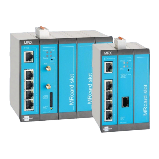
- Page 20 Figure 2: MRX5 Basic Variants The basic variants of the industrial router series MRX have in common that the two left slots are preallocated by a base card with integrated switch as well as a power supply card or a communication card with integrated power supply. The following...
- Page 21 Device Variants Plug-in Cards (MRcards) The MRcards allow a flexible extension of your router to a tailor-made device fpr your application. The left slot is always reserved for the base card with integrated 4+1 port switch that is already present in all basic variants. Depending on the basic variant, the second slot from the left is taken by a power supply card or a commu- nications card with integrated power supply.
- Page 22 Device Variants Figure 12: MRcard Fiber ▪ 2 SFP ports ▪ 2 digital inputs...
- Page 23 • Industrial Router • Quick Installation Guide • Safety Instructions The scope of delivery does not include optional accessories. The following parts are available from your distributor or INSYS icom: • Cellular antennas • Antenna extensions • Din rail power supply units •...
- Page 24 Technical Information Technical Information Basic Variants The following specifications apply to the basic variants MRX3/5 LAN, DSL and LTE. If these variants differ, the different values will be indicated separately. The specifi- cations of the MRcards can be found subsequently. 7.1.1 Technical Data 7.1.1.1 Physical Features All specified data was measured with nominal input voltage, at full load, and an...
- Page 25 MRX DSL 0 °C … 55 °C -25 … 60 °C MRX DSL + MRcard PD / PL / PLS / Fiber 0 °C … 60 °C -25 … 60 °C Table 2: MRX3/5 – physical features – temperature range ...
- Page 26 Technical Information 7.1.1.2 Technological Features Technological Feature Description 4+1-port Ethernet switch 10/100 Mbit/s full/half duplex auto sense; automatic detection of "crossover" or "patch" wiring. Isolation voltage 1.5 kV Table 3: MRX3/5 – technological features The specifications of the cellular engine can be found in the section of the MRcards PL and PLS.
- Page 27 3 W plus 0.5 W per inserted SFP module Table 5: Power consumption estimation Add the values from above table of the MRcards installed in your MRX to the value of the base card (incl. 5+1-port switch). Don't forget to consider the MRcard (PM, PL or PD) already contained in the basic variants.
- Page 28 Technical Information 7.1.5 Connecting the connectors 7.1.5.1 Connectors at the top The connectors are delivered encoded and cannot be interchanged between differ- ent MRcards. The wires are contacted maintenance-free in the connector via a spring clip. Rigid wires (stripped) or stranded wires with end sleeves are only in- serted into the connectors to clamp them.
- Page 29 Technical Information 7.1.6 Certifications The router provides the following certifications: • EMC, Emission: EN 61000-6-3, EN 55032 Class B • EMC, Immunity: EN 61000-6-2, EN 55024 • Product safety: EN 60950-1, IEC/EN 62368-1 The conformity of the whole device depends on the used plug-in cards and corre- sponds to the “least common denominator”...
- Page 30 Technical Information MRcard PM 7.2.1 Technical Data The MRcard PM is integral part of the MRX3/5 LAN and contains the power supply of the MRX. Physical Feature Value Weight 65 g Dimensions (Width x Depth x Height) 27 x 81 x 117 mm Table 9: MRcard PM –...
- Page 31 Technical Information Colour Function blinking 1x during soft reset green via V+ Power Supply 3x during reset to orange via V+ default settings green WAN chain inactive establishing established orange Profile active saved ≠ Info Boot process not Failure Reset completed Table 10: MRcard PM –...
- Page 32 Technical Information 7.2.2.2 Digital inputs The card provides two different digital inputs. Input IN1 is low-active, i.e. active, if connected to GND. Input IN2 is high-active and based on the electrical requirements of the PLC standard DIN EN 61131-2 for digital inputs type 1. You'll find more infor- mation under Technical Data in Table 1.
-
Page 33: Mrcard Pl
The MRcard PL is a plug-in card for extending the basic variants by an LTE cellular modem with integrated power supply. The MRcard PL is already contained in the basic variant MRX LTE. The technical data of the basic variant MRX LAN are ex- tended by the following data with inserted MRcard PL. - Page 34 Technical Information 7.3.1.2 Technological Features Technological Feature Description GSM/GPRS frequencies (2G) 900, 1800 MHz UMTS/HSPA frequencies (3G) 900, 1800, 2100 MHz LTE frequencies (4G) 800, 900, 1800, 2100, 2600 MHz SIM card reader Support for 1.8 V and 3.0 V SIM cards Format: Mini-SIM (2FF), locked Dispatch / receipt GPRS...
-
Page 35: Connections As Well As Display And Control Elements
Technical Information 7.3.2 Connections as well as display and control elements LTE/4G 1 (Primary) cellular antenna 1 (SMA socket) LTE/4G 2 (Secondary) cellular antenna 2 for diversity/MIMO (SMA socket) Figure 17: MRcard PL – connections as well as display and control elements at the front ... - Page 36 Technical Information The LEDs WAN and Info are only active for cards in slot #2 and indicate there the status for the whole device. The function of the Info LED described here corresponds with the default setting, but can be configured differently. Blinking interval LED signal Signal quality 900 ms on, 100 ms off...
- Page 37 Technical Information 7.3.2.2 Digital inputs The card provides two different digital inputs. Input IN1 is low-active, i.e. active, if connected to GND. Input IN2 is high-active and based on the electrical requirements of the PLC standard DIN EN 61131-2 for digital inputs type 1. You'll find more infor- mation under Technical Data in Table 1.
-
Page 38: Antennas
Technical Information 7.3.3 Antennas As per EN 2014/53/EU, the operator of a radio equipment must comply with the harmonisation legislation. This includes in particular the selection and utilisation of suitable antenna systems. It must be ensured in particular that devices with radio technology are not operated without a suitable antenna system for an extended period. -
Page 39: Mrcard Pd
The MRcard PD is already contained in the basic variant MRX DSL. The technical data of the basic variant MRX LAN are ex- tended by the following data with inserted MRcard PD. The MRcard PD is available in two variants, MRcard PD-A and MRcard PD-B, that only differ in the supported DSL standards. -
Page 40: Connections As Well As Display And Control Elements
Technical Information 7.4.1.2 Technological Features Technological Feature Description Supported standards VDSL2 G.993.2 Profile 8a, 8b, 8c, 8d, 12a, 12b, MRcard PD-A 17a. 30a VDSL2 Vectoring G.993.5 ADSL G.992.1 Annex A, G.992.3. Annex A/L/M, G.992.5 Annex A and M, T1.413 Supported standards VDSL2 G.993.2 Profile 8a, 8b, 8c, 8d, 12a, 12b, MRcard PD-B 17a. - Page 41 Technical Information Colour Function blinking 1x during soft re- green via V+ Power Supply 3x during reset to orange via V+ default settings green WAN chain inactive establishing established establishing established green (handshake / (showtime) DSL connec- no con- training) tion nection orange...
- Page 42 Technical Information not connected not connected not connected DSL line connection wire b DSL line connection wire a not connected not connected not connected Figure 21: MRcard PD – DSL socket definition A splitter must be connected upstream when connecting to DSL lines in telephone networks like Annex A or Annex B.
-
Page 43: Mrcard Si
Technical Information MRcard SI The MRcard SI is a plug-in card for extending the basic variants and contains two digital inputs, two digital outputs (changeover relays), a USB connection, a serial RS232 interface as well as a serial RS485 interface. The technical data of the basic variants are extended by the following data with inserted MRcard SI. -
Page 44: Connections And Display Elements
Technical Information 7.5.2 Connections and display elements USB 2.0 interface (socket type A) RS232 Serial RS232 interface (D-Sub connector, V.28) RS485 Serial RS485 interface (EIA-485) Figure 23: MRcard SI – connections and display elements at the front Colour Function green Input 1 not active (LOW) active (HIGH) - Page 45 Technical Information Digital output 2 normally closed (opening contact, NC) – Digital output 2 common contact (COM) – Digital output 2 normally open (closing contact, NO) – Ground Digital input 2 Digital output 1 normally closed (opening contact, NC) – Digital output 1 common contact (COM) –...
- Page 46 Technical Information 7.5.2.2 Digital outputs Both outputs are implemented as change-over relays. The figure below shows an ex- emplary connection. Figure 26: MRcard SI – Digital outputs – connection example 7.5.2.3 USB interface The USB interface is not yet supported by the firmware. The USB interface is designed as USB 2.0 host.
- Page 47 Technical Information 7.5.2.5 RS485 interface Description Common (frame GND) Data line positive Data line negative Table 23: Description of the pin allocation of the RS485 interface The properties of the RS485 interface are configured using a 4-pole DIP switch on the circuit board.
-
Page 48: Mrcard Es
Technical Information MRcard ES The MRcard ES is a plug-in card for extending the basic variants by a 4-port switch. The technical data of the basic variants are extended by the following data with in- serted MRcard ES. 7.6.1 Technical Data 7.6.1.1 Physical Features Physical Feature Value... -
Page 49: Connections And Display Elements
Technical Information 7.6.2 Connections and display elements ETH 1 Ethernet port 1 (RJ45, 10/100 BT) ETH 2 Ethernet port 3 (RJ45, 10/100 BT) ETH 3 Ethernet port 4 (RJ45, 10/100 BT) ETH 4 Ethernet port 5 (RJ45, 10/100 BT) Figure 29: MRcard ES – connections and display elements at the front Each switch port has a green and a yellow LED. - Page 50 Technical Information Physical Feature Value Power consumption Typ. 2.5 W, max. 5 W Level input IN1 HIGH level = 2 ... 24 V LOW level = 0 ... 1 V Contact open condition: HIGH Current consumption input IN1 at LOW Typ.
- Page 51 Technical Information 7.7.1.2 Technological Features Technological Feature Description GSM/GPRS frequencies (2G) 900, 1800 MHz 850, 900, 1800, 1900 MHz (US) UMTS/HSPA frequencies (3G) 900, 1800, 2100 MHz 850, 1700/2100 (AWS), 1900 MHz (US variant) LTE frequencies (4G) 800, 900, 1800, 2100, 2600 MHz 700, 850, 1700/2100 (AWS), 1900 MHz (US variant) SIM card reader...
-
Page 52: Connections As Well As Display And Control Elements
Technical Information 7.7.2 Connections as well as display and control elements RS232 Serial RS232 interface (D-Sub connector, V.28) LTE/4G 1 (Primary) cellular antenna 1 (SMA socket) LTE/4G 2 (Secondary) cellular antenna 2 for diversity/MIMO (SMA socket) Figure 30: MRcard PLS – connections as well as display and control elements at the front ... - Page 53 Technical Information The LEDs WAN and Info are only active for cards in slot #2 and indicate there the status for the whole device. The function of the Info LED described here corresponds with the default setting, but can be configured differently. Blinking interval LED signal Signal quality 900 ms on, 100 ms off...
- Page 54 Technical Information 7.7.2.1 RS232 interface Ring Indication Clear To Send Request To Send Data Set Ready Ground Data Terminal Ready Transmit Data Receive Data Data Carrier Detect Figure 32: RS232 interface The RS232 interface conforms to the layout as DTE (Data Terminal Equipment) 7.7.2.2 Power supply The description of the power supply can be found in the basic variant section.
-
Page 55: Antennas For Mimo / Rx Diversity
Technical Information 7.7.2.4 Digital output The router provides a digital output that is designed as open collector output. You'll find more information in Table 28. The figure below shows two examples for the connection of the output, the connection of a relay on the left and the connection of an LED on the right. - Page 56 Technical Information Physical Feature Value Level inputs Level HIGH = 12 … 24 V Level LOW = 0 … 5 V Contact open condition: LOW Current consumption input at HIGH Max. 2 mA at 24 V DC potential Digital output (relay), max. switch 30 V (DC) / 42 V (AC) voltage Digital output (relay), max.
-
Page 57: Connections And Display Elements
Technical Information 7.8.2 Connections and display elements AI 1 Analogue input 1 AI 2 Analogue input 2 AI 3 Analogue input 3 AO 1 Analogue output 1 Figure 35: MRcard IO – connections and display elements at the front Colour Function green blinks upon DI change... - Page 58 Technical Information Digital input – common contact Digital input 4 Digital input 3 Digital input 2 Digital input 1 Digital output 4 – normally open Digital output 3 – normally open (closing contact) Digital output – common contact Digital output 2 – normally open (closing contact) Digital output 1 –...
-
Page 59: Mrcard Fiber
Technical Information 7.8.2.2 Digital outputs The digital outputs are implemented as normally open relays. The figure below shows an exemplary connection. Figure 38: MRcard IO – Digital outputs – connection example 7.8.2.3 Analogue inputs Description Voltage input (0-10 V) Common – common contact Current input (0-20 mA) Table 36: MRcard IO –... -
Page 60: Technical Data
(refer to Basic Variants also) -30 °C … 55 °C with additionally inserted MRcard PD or when operating in MRX DSL Table 38: MRcard Fiber – physical features The specifications for the power supply can be found in the basic variant section. -
Page 61: Connections As Well As Display And Control Elements
Technical Information 7.9.2 Connections as well as display and control elements SFP1 SFP cage 1 SFP2 SFP cage 2 Figure 39: MRcard Fiber – connections, display and control elements at the front Colour Function blinking 1x for soft reset green via V+ Power Supply... - Page 62 Technical Information The WAN LED is only active for cards in slot #2 and indicates there the status for the whole device. Designation Operation Meaning Reset Press once for a short time. Resets the software and restarts it. (Soft reset) Press at least 3 seconds.
- Page 63 Technical Information 7.9.2.2 Digital inputs The card provides two different digital inputs. Input IN1 is low-active, i.e. active, if connected to GND. Input IN2 is high-active and based on the electrical requirements of the PLC standard DIN EN 61131-2 for digital inputs type 1. You'll find more infor- mation under Technical Data in Table 1.
-
Page 64: Mrcard Installation
MRcard Installation MRcard Installation The industrial router MRX is available in different basic variants and allows a flexi- ble extension of these basic variants with the additionally available MRcards. Pro- ceed as follows to remove or install an MRcard. Caution! The MRX and the MRcards contain electrostatic-discharge- sensitive parts. -
Page 65: Positions And Combinations Of Mrcards
MRcard Installation Positions and Combinations of MRcards The slots in the MRX are enumerated from the left with #1-#3 (MRX3) or . #1-#5 (MRX5). This enumeration is also visible at the base PCB if individual MRcards or front covers are removed. -
Page 66: Slot For Power Supply
MRcard Installation 8.1.2 Slot for power supply Each MRX must be equipped with at least one MRcard PM or MRcard PL in the second slot from the left (#2) which are also contained in the basic variants. If a basic variant that is equipped with an MRcard PM will be upgraded with an MRcard PL, the MRcard PM can be replaced by the MRcard PL, if the additional two supply connections are not required due to reasons of redundancy. -
Page 67: Slots For Extensions
MRcard Installation 8.1.3 Slots for extensions Any other MRcard can be inserted in the third slot (#3) of the MRX3. Any combination of MRcards can be inserted in the other slots (#3-#5) of the MRX5. However, no more than two cellular radio cards like MRcard PL must be in- stalled. -
Page 68: Removal Of An Mrcard
The connectors are disconnected. The MRX is not connected to the power supply. Insert the ball-pen as shown in the following figure vertically from above in the snap-in recess (red arrow) and press it down slightly to release the MRcard or front cover. Repeat the procedure at the bottom. -
Page 69: Installation Of An Mrcard
The connectors are disconnected. The MRX is not connected to the power supply. Place the MRX with its back onto the desktop. Insert the card with the board in the guides or the front cover from above into the slot from above. -
Page 70: Removal Of A Terminal Cover
Removal of a terminal cover Depending on the MRcard to be installed, it might be necessary to remove one or two terminal covers at the top of the MRX to provide an opening for the terminal connectors to the MRcard. -
Page 71: Installation Of A Terminal Cover
When you have removed an MRcard with terminal connector or replaced it by one without terminal connector, you need to insert the terminal cover(s) at the top of the MRX again to re-establish the integrity of the housing. How to install a terminal cover. -
Page 72: Device Label
MRcard Installation Device Label The devices of the industrial router series MRX in their basic variants have a device label attached to one side face that contains various information, which specify the device at hand exactly and also meet legal requirements. If a basic variant will be extended by one or more MRcards, this device label must also be modified accord- ingly. -
Page 73: Assembly
Assembly Assembly This section describes how to mount the MRX to a DIN rail, connect the power supply and uninstall it again. Observe the instructions in the "Safety" section of this manual, in particular the "Safety Instructions for Electrical Installation" for that purpose unconditionally. - Page 74 Assembly Mounting the device to the DIN rail How to mount the router to a DIN rail: Position the device at the DIN rail as seen in the following diagram. There are two snap-in hooks at the upper DIN rail groove. Hook them into place behind the upper edge of the DIN rail when connecting the device.
- Page 75 Assembly Connecting the power supply The device has already been mounted to the DIN rail. The power supply is connected and switched off. Remove the terminal connector from the MRXcard responsible for power supply. Connect the ground lead of the power supply to the terminal "GND" of the terminal connector.
- Page 76 Assembly Removing the device from the DIN rail How to uninstall the router from a DIN rail in a switch cabinet: You will need a flat-blade screwdriver (max. 3.5 mm width). The power supply of the switch cabinet is switched off and secured against being switched on accidentally.
- Page 77 Assembly The plastic spring of the snap-in hook is stretched. While you hold the plastic spring apart with the lower snap-in hook, pull the device away from the DIN rail. Un-hook the device and take it off perpendicularly to the DIN rail. ...
-
Page 78: Commissioning
Commissioning Commissioning This chapter describes how to activate the MRX, i.e. how to connect it to a PC, and how to prepare it for the configuration. Inserting the SIM card (only MRX LTE or MRX LAN with MRcard PL, for MRcard PLS, refer to MRO manual). - Page 79 Locate the RJ-45 socket of the network card at the PC. Plug one end of the network cable into the RJ45 socket of the PC, and the other end into the ETH 1 socket in the left slot of the MRX. ...
- Page 80 Commissioning You should now see the start page of the web interface. The MRX is installed successfully and ready for configuration.
-
Page 81: Operating Principle
Operating Principle Operating Principle This chapter describes how to operate and configure the router. There are different options for configuration and operation: • Via a web-based interface (web interface). The web interface itself is displayed and operated using a web browser. Operation via web interface and access via HTTPS protocol are described in the following. - Page 82 Operating Principle Access to the Web Interface How to access the web interface basically. The device is ready for operation and you have access to it (refer to Commissioning section). Start the web browser and enter the IP address into the address bar. ...
-
Page 83: Authentication To The Router
Operating Principle A session will also be terminated after 15 minutes of inactivity (default setting) due to security reasons. 11.2 Authentication to the Router No authentication is configured in default settings. Access to the web interface is possible without login. Changes can be made. However, the changes can only be activated, after an authentication has been configured. -
Page 84: Authentication Via An Own Certificate Structure
Operating Principle If INSYS MICROELECTRONICS is stored as certification authority in your browser and you access the device again via the HTTPS protocol, the browser indicates again that an invalid security certificate is used. The certificate is not trusted, because the Common Name of the certificate differs from your input in the address bar of the browser. -
Page 85: Profiles And Profile Handling
Operating Principle 11.4 Profiles and Profile Handling The configuration of the router is called profile. Several profiles can be stored on one device so that the configuration of a device can be changed quickly. 11.4.1 Term definitions The following terms or conditions are to be distinguished for profiles: •... -
Page 86: Using Several Profiles
Operating Principle 11.4.3 Using several profiles The versatile possible applications of the router suggest the use of several profiles. The following sections describe the profile handling. 11.4.3.1 Storing a profile Settings made in the opened profile are stored in this profile with a click on the but- ton "OK". -
Page 87: Ascii Configuration
Operating Principle 11.4.3.6 Importing a profile Profiles (in binary format) or ASCII configuration files can be uploaded to the router in the "Administration" menu on the Profiles" page. “ You need to locate the respective file on the computer under "Import profile or ASCII configuration file"... -
Page 88: Maintenance, Troubleshooting And Repair
If a failure occurs during the operation of the product, you will find troubleshooting tips on our support page (https://www.insys-icom.com/en/help/). If you need fur- ther support, please contact your reseller or INSYS icom. You can contact our sup- port team via e-mail under support@insys-icom.de. -
Page 89: Waste Disposal
Waste Disposal Waste Disposal 13.1 Repurchasing of Legacy Systems According to the new WEEE guidelines, the repurchasing and recycling of legacy systems for our clients is regulated as follows: Please send those legacy systems to the following address, carriage prepaid: Frankenberg-Metalle Gaertnersleite 8 D-96450 Coburg... -
Page 90: Declaration Of Conformity
Declaration of Conformity 14.1 Devices with Radio Technology Hereby, INSYS Microelectronics GmbH declares that the device type MRX is in compliance with Directives 2014/53/EU and 2011/65/EU. The full text of the EC Declaration of Conformity is available under the following Internet address: www.insys-icom.com/manual... -
Page 91: Fcc Statement
FCC Statement FCC Statement Note: Certain variants of this device comply with part 15 of the FCC Rules (this is indicated by the FCC symbol on the label). Operation is subject to the following two conditions: (1) This device may not cause harmful interference, and (2) this device must accept any interference received, including interference that may cause unde- sired operation. -
Page 92: Export Restriction
Export Restriction Export Restriction The chip sets for analogue modems and cellular radio adapters used by INSYS Mi- croelectronics GmbH are subject to export restrictions as per US ECCN classifica- tion (5A991). Therefore, it is not allowed to export these communication devices into the follow- ing countries (at the time when this publication has been issued): Cuba, Iran, North Korea, Sudan, Syria The currently effective country list can be found in section „Country Group E“... -
Page 93: Glossary
Glossary Glossary This describes the most important terms and abbreviations of this manual. APN: Access Point Name, computer name that provides cellular subscribers of the GPRS network with Internet access. AT command: Commands to devices such as modems to set up this device. Broadcast: Data packet that is sent to all participants of a network. - Page 94 Glossary GSM: Global System for Mobile communications; cellular network for voice and data transmission. ICMP: Internet Control Message Protocol; protocol that is often used to con- trol a network. The program "ping" uses ICMP for example. Interface: A network device that can transport IP connections. IP address: Internet Protocol address;...
- Page 95 Glossary PPP: Point to Point Protocol; a protocol, which connects two machines via a serial line to enable the exchange of TCP/IP packets between those two machines. PPPoE: Point to Point Protocol over Ethernet; a protocol, which connects two devices via an Ethernet line to enable the exchange of TCP/IP packets between those two machines.
- Page 96 Glossary VPN: Virtual Private Network; logical connections (so-called tunnels) are es- tablished via existing unsafe connections. The end points of these con- nections (tunnel ends) and the devices behind can be considered as an independent logical network. A very high degree of tap- and tamper- resistance can be achieved with the encryption of the data transmis- sion via the tunnels and the previous two-way authentication of the partcipants at this logical network.
-
Page 97: Tables And Diagrams
Tables and Diagrams Tables and Diagrams 18.1 List of Tables Table 1: MRX3/5 – physical features ............... 25 Table 1: MRX3/5 – physical features – temperature range ........25 Table 2: MRX3/5 – technological features ............... 26 Table 3: Basic variants – meaning of the display elements ........26 Table 4: Power consumption estimation .............. - Page 98 Tables and Diagrams Table 34: MRcard IO – meaning of the display elements ........57 Table 35: MRcard IO – Description of the pin allocation of the analogue inputs ..59 Table 36: MRcard IO – Description of the pin allocation of the analogue outputs .. 59 Table 37: MRcard Fiber –...
-
Page 99: List Of Diagrams
18.2 List of Diagrams Figure 1: MRX3 ....................... 20 Figure 2: MRX5 ....................... 20 Figure 3: MRX LAN ....................20 Figure 4: MRX LTE ....................20 Figure 5: MRX DSL....................20 Figure 6: MRcard SI ....................21 Figure 7: MRcard PL ....................21 Figure 8: MRcard ES .................... - Page 100 Figure 47: Terminal cover – Removal ..............70 Figure 48: Terminal cover – Installation ..............71 Figure 49: Example for MRX device label ............... 72 Figure 50: Example for label supplement of an MRcard ......... 72 Figure 51: MRX – dimensions ................. 73 Figure 52: Profile handling –...
-
Page 101: Index
Index Index Access Point Name ......93 Electrical installation......13 Accessories ........23 Environment ......14, 73 Additional information ....... 9 Environmental Protection ....12 AI1 LED ........... 57 Ethernet port ......26, 49 AI2 LED ........... 57 Explosive atmosphere ..... 10 AI3 LED ........... - Page 102 Index MSN ..........94 Safety ..........10 Net address ........94 SCN ..........95 Netmask .......... 94 Scope of Delivery ......23 Network card ........79 Serial interface ......44, 52 Network patch cable ....... 79 Server ..........95 Network rules ........94 Service Center Number ....
Need help?
Do you have a question about the MRX and is the answer not in the manual?
Questions and answers