Table of Contents
Advertisement
Quick Links
Advertisement
Table of Contents

Related Manuals for insys icom MIRO


Summary of Contents for insys icom MIRO
- Page 1 MIRO / MIROdul Installation and User Manual...
- Page 3 Copyright © September 2021 INSYS MICROELECTRONICS GmbH Any duplication of this manual is prohibited. All rights on this documentation and the devices are with INSYS MICROELECTRONICS GmbH Regensburg. Trademarks and logos The use of a trademark or logo not shown below does not indicate that it is freely available for use.
-
Page 4: Table Of Contents
Content Preface ....................6 Defects Liability Terms ..................6 Applicability ......................6 Feedback ......................6 Marking of Warnings and Notes ................7 Meaning of the Symbols and the Formatting in this Manual ........ 8 Security ....................9 Usage According to the Regulations ..............9 Permissible Technical Limits................ - Page 5 Contents Mounting ..................... 26 DIN rail mounting ....................27 7.1.1 DIN rail mounting with integrated adapter ..........27 7.1.2 DIN rail mounting with accessory adapter ..........29 Screw mounting ....................32 Connecting the power supply ................34 Commissioning ..................35 Operating Principle ................
-
Page 6: Preface
We are looking forward to any of your feed- back. Please send an e-mail to support@insys-icom.de. We'd like to know your applications. Please send us a few headwords that we know the applications you solve using products of INSYS icom. -
Page 7: Marking Of Warnings And Notes
MIRO Preface Marking of Warnings and Notes Symbols and Key Words Danger! Risk of severe or fatal injury One of this symbols in conjunction with the key word Danger indicates an imminent danger. It will cause death or severe injuries if not avoided. -
Page 8: Meaning Of The Symbols And The Formatting In This Manual
Preface MIRO Meaning of the Symbols and the Formatting in this Manual This section describes the definition, formatting and symbols used in this manual. The various symbols are meant to help you read and find the information relevant to you. The following text is structured like a typical operating instruction of this manual. -
Page 9: Security
MIRO Security Security The Safety section provides an overview about the safety instructions, which must be observed for the operation of the product. The product is constructed according to the currently valid state-of-the-art technol- ogy and reliable in operation. It has been checked and left the factory in flawless condition concerning safety. -
Page 10: Permissible Technical Limits
Security MIRO Permissible Technical Limits The product is only intended for the use within the permissible technical limits specified in the data sheets. The following permissible limits must be observed: The ambient temperature limits must not be fallen below or exceeded. -
Page 11: Markings On The Product
MIRO Security Markings on the Product The identification plate of the product is either a print or a label on a face of the product. Amongst other things, it can contain the following markings, which are explained in detail here. -
Page 12: Safety Instructions For Electrical Installation
Security MIRO Safety Instructions for Electrical Installation The electrical connection must only be made by authorised expert personnel ac- cording to the wiring diagrams. The notes to the electrical connection in the manual must be observed. Otherwise, the protection category might be affected. -
Page 13: General Safety Instructions
MIRO Security General Safety Instructions Caution! Electrostatic discharges may damage the product! Damage of the product. Observe the general safety precautions when handling electrostatic-discharge-sensitive parts. Caution! Incomplete voltage isolation! Damage of the product. To isolate the voltage from the device, disconnect any supply circuit with its respective isolation device if a redundant power supply is used. - Page 14 Security MIRO Caution! Short circuits and damage due to improper repairs and modifications as well as opening of maintenance areas! Fire hazard and damage of the product. It is not permitted to open the product for repair or modification. Caution! Overvoltage and voltage peaks from the mains supply! Fire hazard and damage of the product due to overvoltage.
-
Page 15: Using Open Source Software
Using Open Source Software General Information Our product MIRO contains, amongst others, so-called open-source software that is provided by third parties and has been published for free public use. The open- source software is subject to special open-source software licenses and the copy- right of third parties. -
Page 16: Special Liability Regulations
Using Open Source Software MIRO Special Liability Regulations We do not assume any warranty or liability, if the open-source software programs contained in our product are used by the customer in a manner that does not com- ply any more with the purpose of the contract, which is the basis of the acquisition of our product. -
Page 17: Version History
MIRO Version History Version History Version Modification Release... -
Page 18: Device Variants
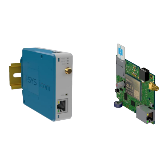
Device Variants This manual describes different variants of the industrial router MIRO and the in- dustrial router module MIROdul of INSYS icom. The routers are referred to as MIRO or MIROdul in this manual. These are: • MIRO-L100 (router with cellular frequency bands for Europe, Middle East, Africa and partly Asia-Pacific region, Australia and South America) •... -
Page 19: Scope Of Delivery
If a part is missing or damaged, please contact your distributor. • Industrial Routers • Quick Installation Guide (MIRO only, 1 per packing unit) • Safety Warnings (MIRO only, 1 per packing unit) The scope of delivery does not include optional accessories. Among other things, the following parts are available from your distributor or INSYS icom: •... -
Page 20: Technical Data
Weight 95 g (MIRO) 40 g (MIROdul) Dimensions (width x height x depth) 26 mm x 77 mm x 99 mm (MIRO) 82 mm x 70 mm x 17 mm (MIROdul) Depth on DIN rail 92 mm (MIRO) Horizontal pitch on DIN rail 1.5 TE (MIRO) -
Page 21: Technological Features
• PS2 classified as per IEC62368-1 • Short-circuit current < 8 A The MIRO can also be mounted transverse in a small distribution box with a width of 4.5 TE using a DIN rail holder that is available as an accessory. -
Page 22: Connections, Display And Control Elements
M2M SIM cards. Compared to standard SIM cards, M2M SIM cards provide significantly increased write cycles and support frequent transitions with this, which may occur in M2M or IoT applications. Connections, display and control elements Figure 1: MIRO / MIROdul – connections, display and control elements Connection Description ETH 1 Ethernet port 1 (RJ45, 10/100 BT) ANT. - Page 23 (Hard reset) Press three times for a Deletes all settings and resets short time within 2 sec- the device to the factory de- onds. faults. Table 7: MIRO – description of the functions and meaning of the control elements...
-
Page 24: Digital Input/Output
The router provides the following certifications: • EMC, Emission: EN 61000-6-3, EN 55032 Class B • EMC, Immunity: EN 61000-6-2, EN 55024 • Product safety: IEC/EN 62368-1 • CE (MIRO-L100, MIROdul-L100) • FCC Part 15 Class B, IC (MIRO-L110, MIROdul-L110) -
Page 25: Antennas
MIRO Scope of Delivery Antennas As per EN 2014/53/EU, the operator of a radio equipment must comply with the harmonisation legislation. This includes in particular the selection and utilisation of suitable antenna systems. It must be ensured in particular that devices with radio technology are not operated without a suitable antenna system for an extended period. -
Page 26: Mounting
Mounting MIRO 7 Mounting The router MIRO can be mounted in two different ways: • DIN rail mounting • Screw mounting The router module MIROdul can only be mounted via screw mounting. This section describes how you can install the router, connect the power supply and demount it again. -
Page 27: Din Rail Mounting
7.1.1 DIN rail mounting with integrated adapter A DIN rail adapter is provided on the MIRO router for DIN rail mounting. Mounting the device to the DIN rail How to mount the router to a DIN rail: Place the device at the DIN rail Hook the upper DIN rail groove into place behind the upper edge of the DIN rail. - Page 28 Mounting MIRO Removing the device from the DIN rail How to remove the router from a DIN rail: The power supply of the switch cabinet is switched off and secured against being switched on accidentally. All connectors at the device are disconnected.
-
Page 29: Din Rail Mounting With Accessory Adapter
Mounting 7.1.2 DIN rail mounting with accessory adapter The MIRO can also be mounted transverse with a significantly smaller installation depth using a DIN rail adapter that is available as an accessory. To do this, the adapter must be mounted to the front of the housing beforehand. - Page 30 Mounting MIRO Mounting the device to the DIN rail How to mount the router to a DIN rail: Place the device at the DIN rail Hook the upper DIN rail groove into place behind the upper edge of the DIN rail.
- Page 31 MIRO Mounting Removing the device from the DIN rail How to remove the router from a DIN rail: The power supply of the switch cabinet is switched off and secured against being switched on accidentally. All connectors at the device are disconnected.
-
Page 32: Screw Mounting
The mounting material is not included and must be selected ac- cording to the underground. The MIRO router must be mounted with two screws (max. Ø 4 mm) to ensure se- cure mounting. The MIROdul router module is to be mounted with three screws (max. Ø 3 mm), whereby only the three holes in the board dimensioned in Figure 8 may be used for mounting. - Page 33 MIRO Mounting Figure 8: Screw mounting – dimensions...
-
Page 34: Connecting The Power Supply
Mounting MIRO Connecting the power supply Connecting the power supply The device is already mounted. The power supply is connected and switched off. Connect the ground lead of the power supply to the terminal "V-”. Connect the positive lead of the power supply to the terminal "V+”. -
Page 35: Commissioning
How to connect the device to a cellular antenna. The power supply is disabled. You will need a suitable cellular antenna (available from INSYS icom). When selecting and mounting the antenna, make sure to comply with CE conformity. - Page 36 Commissioning MIRO Connecting a PC How to connect the router to a PC via a network cable. The power supply is disabled. You will need a Cat 5 network patch cable You will need a network card in the PC.
-
Page 37: Operating Principle
MIRO Operating Principle Operating Principle This chapter describes how to operate and configure the router. There are different options for configuration and operation: • Via a web-based interface (web interface). The web interface itself is displayed and operated using a web browser. Operation via web interface and access via HTTPS protocol are described in the following. - Page 38 Operating Principle MIRO Enter the required settings. Click on the OK button on the according configuration page to save the settings in the profile subsequently. Consider the information in the profile section about the effectivity of configurations made. ...
-
Page 39: Access Via Https Protocol
MIRO Operating Principle Access via HTTPS Protocol The web interface only allows secure configuration using the HTTPS protocol in default settings. The HTTPS protocol allows an authentication of the server (i.e. the router) as well as an encryption of the data transmission. It is not recommended to enable access via the HTTP protocol. -
Page 40: Authentication Via An Own Certificate Structure
Operating Principle MIRO 9.2.2 Authentication via an own certificate structure Alternatively, it is also possible to use an own certificate structure and upload a self-generated certificate/key combination to the router to use this for the access via an HTTPS connection. -
Page 41: Profiles And Profile Handling
MIRO Operating Principle Profiles and Profile Handling The configuration of the router is called profile. Several profiles can be stored on one device so that the configuration of a device can be changed quickly. 9.3.1 Term definitions The following terms or conditions are to be distinguished for profiles: •... -
Page 42: Using Several Profiles
Operating Principle MIRO 9.3.3 Using several profiles The versatile possible applications of the router suggest the use of several profiles. The following sections describe the profile handling. 9.3.3.1 Storing a profile Settings made in the opened profile are stored in this profile with a click on the but- ton "OK". -
Page 43: Ascii Configuration
MIRO Operating Principle 9.3.3.6 Importing a profile Profiles (in binary format) or ASCII configuration files can be uploaded to the router in the "Administration" menu on the “Profiles" page. You need to locate the respective file on the computer under "Import profile or ASCII configuration file"... -
Page 44: Maintenance, Repair And Troubleshooting
Repair Send defect devices with detailed failure description to the source of supply of your device. If you have purchased the device directly from INSYS icom, send the device to: INSYS MICROELECTRONICS GmbH, Hermann-Köhl-Str. 22, 93049 Regensburg. Before dispatching the device: •... -
Page 45: Waste Disposal
MIRO Waste Disposal Waste Disposal 11.1 Repurchasing of legacy systems According to the new WEEE guidelines, the repurchasing and recycling of INSYS legacy devices for our clients is regulated as follows: Please send your legacy devices to the following address: Frankenberg-Metalle Gärtnersleite 8... -
Page 46: Declaration Of Conformity
Declaration of Conformity MIRO Declaration of Conformity Hereby, INSYS Microelectronics GmbH declares that the device types MIRO and MIROdul are in compliance with Directives 2014/53/EU and 2011/65/EU. The full text of the EC Declaration of Conformity is available under the following Internet address: www.insys-icom.com/manual... -
Page 47: Fcc Statement
MIRO FCC Statement FCC Statement Note: Certain variants of this device comply with part 15 of the FCC Rules (this is indicated by the FCC symbol on the label). Operation is subject to the following two conditions: (1) This device may not cause harmful interference, and (2) this device must accept any interference received, including interference that may cause unde- sired operation. -
Page 48: Export Restriction
Export Restriction MIRO Export Restriction The chip sets for analogue modems and cellular radio adapters used by INSYS Mi- croelectronics GmbH are subject to export restrictions as per US ECCN classifica- tion (5A991). Therefore, it is not allowed to export these communication devices into the follow-... -
Page 49: Glossary
MIRO Glossary Glossary This describes the most important terms and abbreviations of this manual. APN: Access Point Name, computer name that provides cellular subscribers of the GPRS network with Internet access. AT command: Commands to devices such as modems to set up this device. - Page 50 Glossary MIRO GSM: Global System for Mobile communications; cellular network for voice and data transmission. ICMP: Internet Control Message Protocol; protocol that is often used to con- trol a network. The program "ping" uses ICMP for example. Interface: A network device that can transport IP connections.
- Page 51 MIRO Glossary PPP: Point to Point Protocol; a protocol, which connects two machines via a serial line to enable the exchange of TCP/IP packets between those two machines. PPPoE: Point to Point Protocol over Ethernet; a protocol, which connects two devices via an Ethernet line to enable the exchange of TCP/IP packets between those two machines.
- Page 52 Glossary MIRO VPN: Virtual Private Network; logical connections (so-called tunnels) are es- tablished via existing unsafe connections. The end points of these con- nections (tunnel ends) and the devices behind can be considered as an independent logical network. A very high degree of tap- and tamper-...
-
Page 53: Tables And Diagrams
Table 5: MIRO – meaning of the display elements ..........23 Table 6: Blinking code of the signal LED ..............23 Table 7: MIRO – description of the functions and meaning of the control elements ..........................23 Table 8: Permissible wire cross-sections for connectors ........24 Table 9: Permissible line lengths ................ -
Page 54: Index
Index MIRO Index Access Point Name ......49 General safety instructions ....13 Accessories ........19 GPRS ..........49 Additional information ....... 8 Ground ..........22 Alternative results ......8 GSM ..........50 APN ..........49 Housing ........... 14 Assembly ......... 26 HTTPS .......... - Page 55 MIRO Index Permissible limit ......10 Service Center Number ....51 Personnel ........10 Short-cut ........14, 44 PIN ..........35 SIG LED ........... 23 Port ..........50 SIM card .......... 35 Port forwarding ....... 50 SIM card reader ....... 21 Power consumption ......
Need help?
Do you have a question about the MIRO and is the answer not in the manual?
Questions and answers