Table of Contents
Advertisement
Quick Links
Advertisement
Table of Contents

Related Manuals for insys icom GPRS 5.1


Summary of Contents for insys icom GPRS 5.1
- Page 1 INSYS GPRS 5.1 Ethernet...
- Page 3 Copyright © July 11 INSYS MICROELECTRONICS GmbH Any duplication of this manual is prohibited. All rights on this documentation and the devices are with INSYS MICROELECTRONICS GmbH Regensburg. Trademarks The use of a trademark not shown below is not an indication that it is freely avail- able for use.
-
Page 4: Table Of Contents
Contents Preface......................... 6 Defects Liability Terms .......................6 Marking of Warnings and Notes ..................7 1.2.1 Symbols and Key Words ....................7 Symbols and the Formatting in this Manual ..............8 Safety ........................9 Usage According to the Regulations ..................9 Permissible Technical Limits.....................10 Responsibilities of the Operator..................10 Qualification of the Personnel ..................10 Instructions for Transport and Storage................10 Markings on the Product ....................11... - Page 5 Contents Functions ......................36 12.1 Status ..........................36 12.2 GSM/GPRS.........................37 12.2.1 Establishment of the WAN Connection ..............37 12.2.2 Mobile Radio Parameters....................37 12.2.3 Periodic Logout/Login and Periodic Restart ............. 39 12.2.4 Internet Connection Check................... 39 12.3 LAN ............................40 12.3.1 LAN Settings ........................40 12.4 NAT............................41 12.4.1 NAT Settings ........................
-
Page 6: Preface
Preface INSYS GPRS 5.1 Preface This manual allows fort he safe and efficient use of the product. The manual is part of the product and must always be stored accessible for installation, commissioning and operating personnel. Defects Liability Terms A usage not according to the intended purpose, an ignorance of this documentation, the use of insufficiently qualified personnel as well as unauthorised modifications exclude the liability of the manufacturer for damages resulting from this. -
Page 7: Marking Of Warnings And Notes
INSYS GPRS 5.1 Preface Marking of Warnings and Notes 1.2.1 Symbols and Key Words Danger! Risk of severe or fatal injury One of these symbols in conjunction with the key word Danger indicates an imminent danger. It will cause death or severe in- juries if not avoided. -
Page 8: Symbols And The Formatting In This Manual
Preface INSYS GPRS 5.1 Symbols and the Formatting in this Manual This section describes the definition, formatting and symbols used in this manual. The various symbols are meant to help you read and find the information relevant to you. The following text is structured like a typical operating instruction of this manual. -
Page 9: Safety
INSYS GPRS 5.1 Safety Safety The Safety section provides an overview about the safety instructions, which must be observed for the operation of the product. The product is constructed according to the currently valid state-of-the-art technology and reliable in operation. It has been checked and left the factory in flawless condition concerning safety. -
Page 10: Permissible Technical Limits
Safety INSYS GPRS 5.1 Permissible Technical Limits The product is only intended for the use within the permissible technical limits specified in the data sheets. The following permissible limits must be observed: The ambient temperature limits must not be fallen below or exceeded. -
Page 11: Markings On The Product
INSYS GPRS 5.1 Safety Markings on the Product The identification plate of the product is either a print or a label on a face of the product. Amongst other things, it contains the following markings, which are explained in detail here. -
Page 12: General Safety Instructions
Safety INSYS GPRS 5.1 General Safety Instructions Caution! Moisture and liquids from the environment may seep into the interior of the product! Fire hazard and damage of the product. The product must not be used in wet or damp environments, or in the direct vicinity of water. - Page 13 INSYS GPRS 5.1 Safety Caution! Distance from antennas to persons! A too low distance from GSM antennas to persons can affect the health. Please observe to keep a minimum distance of 20 cm between the GSM antenna and persons during operation.
-
Page 14: Scope Of Delivery
INSYS GPRS 5.1 Scope of Delivery The scope of delivery for the INSYS GPRS 5.1 Ethernet includes all accessories listed be- low. Please check if all accessories are included in the box. If a part is missing or dam- aged, please contact your distributor. -
Page 15: Further Information
Basic information about topics, like mobile radio and network technology that may be helpful when integrating the product of INSYS icom into your application, can be found in our Knowledge Base that will be continuously updated. You can find the Knowledge Base under http://www.insys-icom.com/knowledge/... -
Page 16: Technical Data
Technical Data INSYS GPRS 5.1 Technical Data Physical Features Caution! Overvoltage and voltage peaks from the mains supply! Fire hazard and damage of the product due to overvoltage. Install suitable overvoltage protection. All specified data was measured with nominal input voltage, at full load, and an ambient temperature of 25°C. -
Page 17: Technological Features
INSYS GPRS 5.1 Technical Data Technological Features Technological Feature Description GSM frequencies (2G) 850, 900, 1800, 1900 MHz SIM card reader Support for 1.8 V and 3.3 V SIM cards SMS dispatch; incoming SMS can be received, but cannot be accessed via the web interface. -
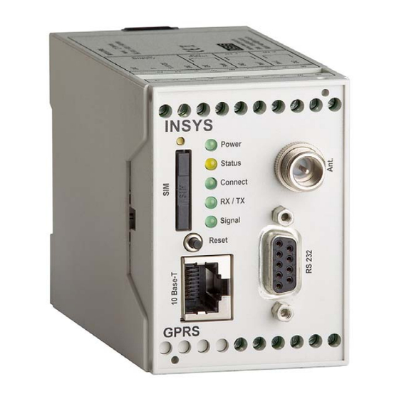
Page 18: Display And Control Elements
Display and Control Elements INSYS GPRS 5.1 Display and Control Elements Figure 1: Display and control elements on the front of the device Position Description Reset key SIM card holder SIM card eject button Power LED Status LED Connect LED... -
Page 19: Meaning Of The Displays
Description Operation Meaning Reset key Press for at least 1 second. Resets the hardware and restarts the INSYS GPRS 5.1 Ethernet. (Hard reset) Press five times for a short Deletes all settings of the time within 10 seconds. INSYS GPRS 5.1 Ethernet and resets the device to the fac- tory defaults. -
Page 20: Connections
Connections INSYS GPRS 5.1 Connections Front Panel Connections Figure 2: Connections on the front panel of the device Position Description Ethernet port (RJ45) Serial interface (without function) GSM antenna connection (FME socket) Table 7: Description of the connections on the front panel of the device... -
Page 21: Terminal Connections On The Top
INSYS GPRS 5.1 Connections Terminal Connections on the Top Figure 3: Connections on the top of the device Terminal Description Description Ground reserved 10 ... 60 VDC Power supply 10 V – 60 V DC Ground Ground Reset Reset input... -
Page 22: Terminal Connections On The Bottom
Connections INSYS GPRS 5.1 Terminal Connections on the Bottom Figure 4: Connections on the bottom of the device Terminal Description Description Out 1-NC Output 1 normally closed Out 1 Output 1 Out 1-NO Output 1 normally open Out 2-NC Output 2 normally closed... -
Page 23: Lan Connection
INSYS GPRS 5.1 Connections LAN Connection Table 10: RJ45 connector Ethernet cable Signal Description Receive positive Receive negative Transmit positive Not connected Not connected Transmit negative Not connected Not connected Table 11: Description of the pin allocation of the RJ45 connector... -
Page 24: Function Overview
The INSYS GPRS 5.1 Ethernet provides you with the following functions: Configuration via web interface All functions of the INSYS GPRS 5.1 Ethernet can be configured and set via a web interface. The access to the web interface is protected with a user name and password query. - Page 25 The assigned IP address can be deposited at a dynamic DNS service (e.g. DynDNS) after the set-up of a PPPoE connection to an internet service pro- vider . The INSYS GPRS 5.1 Ethernet can be contacted out of the Internet. Firmware update via web interface The firmware of the INSYS GPRS 5.1 Ethernet can be updated via the web...
-
Page 26: Mounting
INSYS GPRS 5.1 Mounting This section describes how to mount the INSYS GPRS 5.1 Ethernet to a DIN rail, con- nect the power supply and uninstall it again. Observe the instructions in the "Safety" section of this manual, in particular the "Safety Instructions for Electrical Installation"... - Page 27 INSYS GPRS 5.1 Ethernet. Hook the upper one into place behind the upper edge of the DIN rail. Lift the INSYS GPRS 5.1 Ethernet perpendicular to the DIN rail until the two lower, flexible snap-in hooks engage in the DIN rail.
- Page 28 The INSYS GPRS 5.1 Ethernet is disconnected from the power supply. Uninstalling the device from the DIN rail How to uninstall the INSYS GPRS 5.1 Ethernet from a DIN rail in a switch cabinet: You will need a Phillips screwdriver with a 4.5 mm blade.
- Page 29 The plastic spring of the snap-in hook is stretched. While you hold the plastic spring apart with the lower snap-in hooks, pull the INSYS GPRS 5.1 Ethernet away from the DIN rail. Un-hook the INSYS GPRS 5.1 Ethernet and take it off perpendicularly to the DIN rail. ...
-
Page 30: Commissioning
This chapter describes how to activate the INSYS GPRS 5.1 Ethernet, i.e. how to connect the INSYS GPRS 5.1 Ethernet to a PC, and how to prepare it for the configuration. Connecting the INSYS GPRS 5.1 Ethernet to a GSM antenna and a PC How to connect the INSYS GPRS 5.1 Ethernet to a GSM antenna and, via a... - Page 31 Check, whether your INSYS GPRS 5.1 Ethernet is supplied with power. If yes, most probably a wrong IP address is configured in the INSYS GPRS 5.1 Ethernet. Press the reset key at the INSYS GPRS 5.1 Et hernet five times within 10 seconds and repeat this instruc- tion from step 2.
- Page 32 You have entered the associated PIN into the INSYS GPRS 5.1 Ethernet. If no or a wrong PIN is entered into the INSYS GPRS 5.1 Ethernet, the SIM card will be locked by an automated, repeated handover of the wr ong PIN! ...
- Page 33 Enable the power supply of the INSYS GPRS 5.1 Ethernet again. The INSYS GPRS 5.1 Ethernet is ready for operation with this. As soon as the Status LED is illuminated permanently, the INSYS GPRS 5.1 Ethernet is ready for routing.
-
Page 34: Operating Principle
The web interface allows easy configuration of the INSYS GPRS 5.1 Ethernet using a web browser. All functions of the INSYS GPRS 5.1 Ethernet can be configured via the interface. The interface is bilingual (German/English) and can be switched using the "DE"... - Page 35 INSYS GPRS 5.1 Operating Principle Enter the required settings. Click on the Sa ve button on the according configuration page to save the settings. After yo u completed the co nfiguration changes, always click the button Save . Otherwise the settin gs will be lost as soon as you change to another page or close the browser.
-
Page 36: Functions
Under "Primary DNS Server", the first DNS server provided by the provider is displayed. Under "Secondary DNS Server", the second DNS server provided by the provider is dis- played. Under "LAN IP Address", the currently configured IP address of the INSYS GPRS 5.1 Ethernet on the locale side is displayed. -
Page 37: Gsm/Gprs
The INSYS GPRS 5.1 Ethernet will need the PIN of the inserted SIM card (if the SIM card is protected by a PIN) to register with the mobile network and establish CSD or IP connec- tions. - Page 38 In order to select the network selection, use the radio buttons to choose if th INSYS GPRS 5.1 Ethernet should log into the strongest network, to a preferred provider and its network, or exclusively into the network of a provider deter- mined by you.
-
Page 39: Periodic Logout/Login And Periodic Restart
Functions 12.2.3 Periodic Logout/Login and Periodic Restart The INSYS GPRS 5.1 Ethernet can logout from the mobile network and login again (after one minute) or perform a restart. Using periodic logout and log in or a restart, you will increase the availability of the INSYS GPRS 5.1 Ethernet, which may otherwise be im- paired by several circumstanc es, which require a re-login into the network, e.g. -
Page 40: Lan
Output 2 remains enabled as long as the LAN connection is established. If input 2 is opened again, the LAN interface will be disabled again. It must be possible to access the INSYS GPRS 5.1 Ethernet in the LAN under a certa in IP address. -
Page 41: Nat
Only the p ublic IP address of the INSYS GPRS 5.1 Ethernet can be reached in the Internet. This IP add ress can still be used to access the local end terminals in the network of the INSYS GPR S 5.1 Ethernet from the Internet, if NAT and port forwarding are used. - Page 42 In order to create a new static NAT entry, enter under "New static NAT-Entry" the port on the WAN side of the INSYS GPRS 5.1 Ethernet, at which IP packets are to be accepted, into the "WAN Port" field, the IP address of the destination computer in the local network into the "L...
-
Page 43: Dyndns
Internet, also for dynamically allocate IP addresses (if the allocated IP address for incoming connections is not protected). The INSYS GPRS 5.1 Ethernet will update the IP address connected to the domain name at the DynDNS provider during each dial-up. For... -
Page 44: Administration
Restart and Resetting the Default Settings You can reset the INSYS GPRS 5.1 Ethernet via the web interface or by pressing the reset key on the front of the device. You can simply restart your device or reset all settings to factory defaults. -
Page 45: Firmware Update
The firmware of the INSYS GPRS 5.1 Ethernet can be updated on the "FW-Update" page. 12.7.1 Updating the Firmware You can update the firmware of the INSYS GPRS 5.1 Ethernet. The firmware is a comb ina- tion of operating system and programs, in which the functions of the {{PRO- DUKTBEZEICHNUNG}}} are implem ented. -
Page 46: Maintenance, Repair And Troubleshooting
+49 941 58692-0. Repair Send defect devices with detailed failure description to the source of supply of your de- ice. If you have purchased the device directly from INSYS icom, send the device to: INSYS ICROELECTRONICS GmbH, Waffnergasse 8, 93047 Regensburg. Caution! Short circuits and damage due to improper repairs and modifi- cations as well as opening of products. -
Page 47: Waste Disposal
INSYS GPRS 5.1 Waste Disposal Waste Disposal 14.1 Repurchasing of Legacy Systems According to the new WEEE guidelines, th e repurchasing and recycling of legacy systems for our clie nts is regulated as follows: Please send those legacy systems to the following address, carriage prepaid:... -
Page 48: Declaration Of Conformity
Declaration of Conformity INSYS GPRS 5.1 Declaration of Conformity This device complies with the requirements set out in the Council Directive on the Ap- proximation of the Laws of the Member States relating to Electromagnetic Compatibility 2004/10 8/EC and the Council Directive relating to Low Voltage 2006/95/EC as well as he Council Directive R&TTE 1999/5/EC. -
Page 49: Export Regulation
INSYS GPRS 5.1 Export Regulation Export Regulation US American export regulations apply to the chip sets used by INSYS Microelectronics GmbH for analogue modems and cellular radio adapters according to ECCN classificati 5A991. At the t ime of publicat ion of this docume t, it is thus not allowed o export these com-... -
Page 50: Gprs Dial-Up Parameters
GPRS Dial-Up Parameters INSYS GPRS 5.1 GPRS Dial-Up Parameters Here is an overview of network providers for German speaking countries (D, A, CH). Ac- cess data of further European network providers is available under http://www.insys- tec.de/en/content/knowledge-base/mobile/apn/ Network provider User name... -
Page 51: Faq - Frequently Asked Questions
FAQ – Frequently Asked Questions You ca n find a selection of frequently asked questions in conjunction with the commi sioning and operation of the INSYS GPRS 5.1 Ethernet and possible solutions here. Problem Possible cause Remedy The INSYS GPRS 5.1... -
Page 52: International Safety Instructions
International Safety Instructions INSYS GPRS 5.1 International Safety Instructions The following safety instruction of Cinterion is valid for the used GPRS engine TC63i or EDGE engine MC75i. Following US FCC specifications, each device must have a sticker with a note referring to the “FCC ID” attached. - Page 53 INSYS GPRS 5.1 International Safety Instructions IMPORTANT! Cellular terminals or mobiles operate using radio signals and cellular networks. Be- cause of this, connection cannot be guaranteed at all times under all conditions. Therefore, you should never rely solely upon any wireless device for essential com unications, for example emergency calls.
-
Page 54: Glossary
Glossary INSYS GPRS 5.1 Glossary The most imp ortant terms and abbreviations used in the manual are shortly described below. APN: The Access Point Name is the name of the processor offering internet ac- cess to the mobile subscribers of GPRS... - Page 55 INSYS GPRS 5.1 Glossary ICMP: The Internet Control Message Protocol is a protocol which is often used f the control of a network. The progr am “ping” for example uses ICMP. IP-Addres The Internet Protocol Address is the IP address of a device inside a network at which it can be reached.
- Page 56 Glossary INSYS GPRS 5.1 Socket: Data connections coming about by ->TCP or ->UDP work with sockets for addressing. A socket consists of an IP address and of a port (cp. Address: Street Name and Street Numb Switch: A device which can connect several machines to the Ethernet. Contrary to a hub the switch is „intelligent“, i.e.
-
Page 57: Tables And Diagrams
INSYS GPRS 5.1 Tables and Diagrams Tables and Diagrams 21.1 List of Tables Table 1: Physical Features ........................16 Table 2: Technological Features ......................17 Table 3: Description of the display and con trol e lements on the front panel of the device ................. -
Page 58: Index
Index INSYS GPRS 5.1 Index Access data ..........33, 50 Ethernet cable..........15 Accessories ...........15 Ethernet port..........21 Additional information ....... 9 Explosive atmosphere .......10 Alternative results ........9 Field strength ..........38 APN ..........33, 39, 50, 54 Fire hazard ............13 AT command..........54 Firewall ............54... - Page 59 INSYS GPRS 5.1 Index Moisture ..........12, 27 Responsibilities of the operator....11 Mounting ............27 Restart.............40, 44 MSN ..............55 RJ45 connector Ethernet cable....24 AT ............25, 42 Roaming............38 NAT table ............42 Router.............55 Net mask ............55 RX/TX LED............19 Network address.........55 RX/TX LED............20 Network patch cable........32...
- Page 60 Index INSYS GPRS 5.1 WAN ............25, 56 Water spray ...........12, 27 WAN connection........39, 41 Web interface ....25, 26, 36, 38, 44...
Need help?
Do you have a question about the GPRS 5.1 and is the answer not in the manual?
Questions and answers