
Related Manuals for Extron electronics FOX3 SR 20


Summary of Contents for Extron electronics FOX3 SR 20
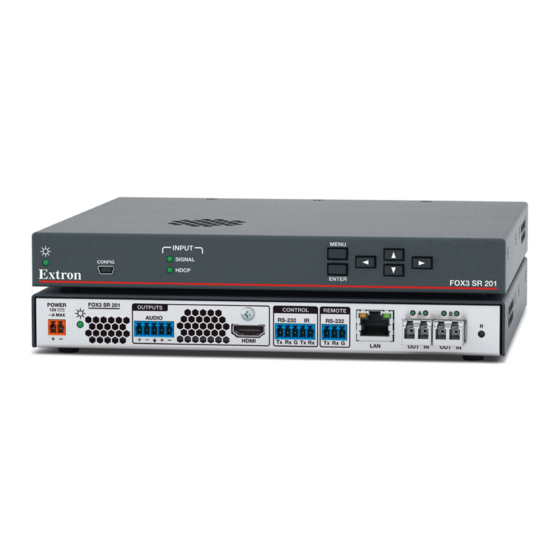
- Page 1 User Guide Fiber Optic Extender FOX3 SR 201 Fiber Optic HDMI Scaling Receiver 68-2888-01 Rev. A 05 21...
- Page 2 Safety Instructions...
- Page 3 Copyright © 2021 Extron. All rights reserved. www.extron.com Trademarks All trademarks mentioned in this guide are the properties of their respective owners. The following registered trademarks ( ® ), registered service marks ( ), and trademarks ( ) are the property of RGB Systems, Inc. or Extron (see the current list of trademarks on the Terms of Use page at www.extron.com):...
- Page 4 FCC Class A Notice This equipment has been tested and found to comply with the limits for a Class A digital device, pursuant to part 15 of the FCC rules. The Class A limits provide reasonable protection against harmful interference when the equipment is operated in a commercial environment.
- Page 5 Conventions Used in this Guide Notifications The following notifications are used in this guide: WARNING: Potential risk of severe injury or death. AVERTISSEMENT : Risque potentiel de blessure grave ou de mort. Risk of minor personal injury. CAUTION: ATTENTION : Risque de blessure mineure.
-
Page 7: Table Of Contents
Contents Introduction ..........1 SIS Configuration and Control ....21 About this Guide ..........1 Host Control Ports ..........21 Product Description ..........1 Rear Panel RS-232 Port ........ 21 Fiber Cable Transmission Modes ..... 2 Front Panel Configuration USB Port ....21 Extron LinkLicense........... - Page 8 Equipment Mounting ......... 47 Mounting the Scaling Receiver......47 Tabletop Use ..........47 Mounting kits ..........47 UL Rack-Mounting Guidelines ....... 47 FOX3 SR 201 Scaling Receiver • Contents viii...
-
Page 9: Introduction
Introduction WARNING: The FOX3 SR 201 output continuous invisible light (Class 1 rated), which may be harmful to the eyes; use with caution. AVERTISSEMENT : Le FOX3 SR 201 émet une lumière invisible en continu (conforme à la classe 1) qui peut être dangereux pour les yeux, à utiliser avec précaution. •... -
Page 10: Fiber Cable Transmission Modes
Fiber Cable Transmission Modes The receiver is further categorized by the type of fiber optic cable, multimode or singlemode, which define the effective range of transmission: Multimode — Long distance, up to 500 m (1640 feet) (depending on the fiber cable) Singlemode —... -
Page 11: Extron Linklicense
Extron LinkLicense An Extron LinkLicense unlocks features that add convenience, expand system options, and enhance the capabilities of Extron products. Each LinkLicense can be purchased separately from the FOX3 device and activated as the need arises (A LinkLicense can be uploaded using Extron Toolbelt software and the Toolbelt Help File. - Page 12 Aspect ratio control — The aspect ratio of the video output can be controlled by • selecting a FILL mode, which provides a full screen output, or a FOLLOW mode, which preserves the original aspect ratio of the input signal. •...
-
Page 13: Installation
Installation This section details the installation of the FOX3 SR 201 receiver, including: Installation Overview • • Rear Panel Features • Connector and Cable Details Installation Overview Follow these steps to install and set up an Extron FOX3 SR 201 receiver for operation: Turn off all of the equipment. Ensure that the video source and the output display are all turned off and disconnected from the power source. - Page 14 Power LED — The lit LED indicates power is applied. Audio output — This 5-pole, captive screw port outputs the transmitted, unamplified, Analog Audio Connector line level analog audio (see on page 9 to wire this connector). NOTE: If embedded digital audio is present on the HDMI output, this analog audio connector outputs audio unless embedded audio is in multi-ch format.
- Page 15 — (see figure 2) SFP module and LEDs WARNING: The devices output continuous invisible light (Class 1 rated), which may be harmful to the eyes; use with caution. Plug the attached dust cap into the optical transceiver when the fiber optic cable is unplugged. AVERTISSEMENT : Le produit émet une lumière invisible en continu (conforme à...
-
Page 16: Connector And Cable Details
Connector and Cable Details HDMI Connectors HDMI signals run at a very high frequency and are especially prone to errors caused by bad video connections, too many adapters, or excessive cable length. To avoid the loss of an image or jitter, follow these guidelines: Limit or avoid the use of adapters. -
Page 17: Analog Audio Connector
Analog Audio Connector See figure 5 to wire the connector for the analog audio. Connectors are included with the Ring Sleeve Sleeves receiver, but you must supply the audio cable. Use the supplied tie-wraps to strap the cable Sleeve Ring to the extended tail of the connectors. Unbalanced Stereo Input Balanced Stereo Input No Ground Here... - Page 18 ATTENTION: • The length of the exposed wires in the stripping process is important. The ideal length is 3/16 inches (5 mm). Any longer and the exposed wires may touch, causing a short circuit between them. Any shorter and the wires can be easily pulled out even if tightly fastened by the captive screws.
-
Page 19: And Ir Connectors
RS-232 and IR Connectors Figure 6 shows how to wire the Control (RS-232 and IR) and Remote (RS-232) connectors. IR Device CONTROL RS-232 Device Figure 6. Control and Sync Connectors Wiring NOTES: • The IR Tx and Rx line pair and the RS-232 Tx and Rx line pair must each cross once between this connector and the source or destination. -
Page 20: Operation
Operation This section details the operation of the FOX3 SR 201 scaling receiver, including: Front Panel Features • • Operations • Using the On-Screen Menu System Reset Modes • • Front Panel Lockout (Executive Mode) Configuration • • Audio Configuration Front Panel Features MENU INPUT CONFIG... -
Page 21: Using The On-Screen Menu System
Using the On-Screen Menu System The OSD menus are used primarily for the initial setup of the device. The on-screen menu presents configuration options on a local monitor and can be adjusted with front panel controls. NOTE: The on-screen menu has a default timeout of 60 seconds. Menu Selection Buttons •... -
Page 22: Using The Menu Screens
Using the Menu Screens To open the on-screen menu: Connect a display device to the HDMI output (see figure 2 page 5). Press the Menu or Enter button to open the on-screen menu. To navigate the on-screen menu: Press the and buttons to move through the submenus (left) panel. -
Page 23: Device Info Submenu
Device Info Submenu Figure 11. Device Info Submenu The read-only Device Info screen is listed first in the submenus (left) panel. This screen contains information about the FOX3 scaling receiver, including unit name, firmware version, internal temperature in Celsius and Fahrenheit, selected input device format and signal information, and output signal information for all outputs. -
Page 24: Reset Modes
• HDMI Format — After selecting HDMI Format press the or buttons to select the output format. The format choices include: Auto (based on the EDID of the sink) (default) • • DVI RGB 444 (no audio, no Infoframe) •... - Page 25 Perform resets of the unit as follows: Mode 1 RESET RESET Press and hold Apply power Release Reset button. the Reset button. to the FOX3. Release, then immediately Mode 4 press and release again. Reset LED flashes twice. Reset LED flashes, then stays on. RESET RESET RESET...
-
Page 26: Front Panel Lockout (Executive Mode)
Front Panel Lockout (Executive Mode) The FOX3 scaling receiver has a front panel security lock that locks out all front panel controls. Executive mode can be enabled via PCS (see the FOX3 SR 201 Using PCS Help File) or via the front panel buttons. To enable or disable front panel lockout via the front panel buttons: •... -
Page 27: Insertion
RS-232 Insertion A user can connect a control system to send and receive RS-232 data over the fiber and the captive screw port of the transmitter and receiver. Captive Screw Insertion A user can connect an RS-232 signal from a control system to an endpoint and pass that signal over the fiber to the connected endpoint. -
Page 28: Audio Configuration
Audio Configuration Audio De-embedding The FOX3 supports a single audio signal to pass LPCM-2CH. When the audio from the transmitter is LPCM-2CH, the HDMI audio signal is output on the HDMI output and the analog audio output. Audio Output Volume Adjust the overall output volume level for the receiver analog audio output as well as the embedded LPCM-2CH audio on the HDMI output via PCS (see the FOX3 SR 201 Help File) or SIS command (see... -
Page 29: Sis Configuration And Control
SIS Configuration and Control This section describes the remote control operation of the FOX3 SR 201 scaling receiver, including: • Host Control Ports • Simple Instruction Set Control • Command and Response Table for SIS Commands The FOX3 receiver can be configured using SIS commands, PCS, or embedded web pages. -
Page 30: Establishing A Connection
Default IP address To access the FOX3 receiver via the LAN port, the IP address, subnet mask, and the gateway address for the devices are needed. If the addresses have not been changed, the factory‑specified defaults are: 192.168.254.254 • IP address Gateway address 0.0.0.0 •... -
Page 31: Simple Instruction Set Control
Simple Instruction Set Control Host-to-Unit Instructions SIS commands consist of one or more characters per field. No special characters are required to begin or end a command character sequence. When a command is valid, the receiver executes the command and sends a response to the host device. All responses from the receiver to the host end with a carriage return and a line feed (CR/LF = ), which signals the end of the response character string. -
Page 32: Using The Command And Response Table
Using the Command and Response Table The command and response table begins below. Symbols are used throughout the table to represent variables in the command and response fields. Command and response examples are shown throughout the table. The ASCII to HEX conversion table below is for use with the command and response table. -
Page 33: Common Symbol Definitions
Common symbol definitions Carriage return/line feed space • } or Carriage return (no line feed) or W = Escape key 0 = Unmute (default) 1 = Mute video only = Video mute 2 = Mute video and sync = Audio output 1 = Digital (Rx HDMI Out) 2 = Analog (Rx Analog Output) 3 = All outputs (digital and analog) - Page 34 SIS Variable ( ) for Selected Output Resolution and Refresh Rate Combinations Resolution 23.98 Hz 24 Hz 25 Hz 29.97 Hz 30 Hz 50 Hz 59.94 Hz 60 Hz 640x180 800x600 1024x768 1280x768 1280x800 1280x1024 1360x768 1366x768 1440x900 1400x1050 1600x900 1680x1050 1600x1200 1920x1200...
-
Page 35: Command And Response Table For Sis Commands
Command and Response Table for SIS Commands SIS Command Response Additional description Command Function (Host to Unit) (Unit to Host) Video mute Mute output video only Vmt1 Mute output video and sync Vmt2 Unmute video and sync Default Vmt0 View mute status Verbose mode 2/3: KEY: = Video mute... - Page 36 SIS Command Response Additional description Command Function (Host to Unit) (Unit to Host) Information requests (continued) X& X2(] Information request SFPALnk SFPBLnk SigI HdcpI HdcpO AudI • • • • • • • Verbose mode 2/3: X& X2(] Inf00*SFPALnk SFPBLnk SigI HdcpI HdcpO...
- Page 37 SIS Command Response Additional description Command Function (Host to Unit) (Unit to Host) IP address E X1! X1!] Set IP address Ipi• X1!] View IP address = IP address KEY: xxx.xxx.xxx.xxx RS-232 COMM settings EX1^ X1%] Set serial port parameters •...
- Page 38 SIS Command Response Additional description Command Function (Host to Unit) (Unit to Host) Output scaler rate E X2$ X2$] Set output rate RATE Rate Set output rate to X2$] View current output rate RATE Verbose mode 2/3 X2$] Rate = Scaler resolution 3‑digit response with padding (see Resolution table...
-
Page 39: Configuration Software
Configuration Software The FOX3 SR 201 scaling receiver can be easily configured using Extron Product Configuration Software (PCS). This section describes the software installation and communication (see the FOX3 SR 201 PCS Help File for detailed control information). The topics covered in this section are: Software/Firmware Installation •... - Page 40 Scroll down to the alphabetic navigation bar (see figure 17). Figure 17. Software Installation Click the appropriate letter to locate the software or firmware. Click Download and follow the on-screen instructions (see figure 18, for PCS). Figure 18. PCS Software Download For Firmware: Figure 19.
-
Page 41: Connecting To Pcs
Connecting to PCS The Extron PCS window opens with the Device Discovery panel open. Connect to the device using the Device Discovery panel or the TCP/IP panel (see figure 20). Device Discovery Panel The Device Discovery panel displays accessible Extron devices connected directly to the PC or to a LAN or WAN. -
Page 42: Tcp/Ip Panel
TCP/IP Panel The TCP/IP panel connects PCS to a specific device through Ethernet or USB over IP. Figure 22. TCP/IP Panel Click the TCP/IP tab (see figure 22, In the IP Address/Hostname field ( ), enter the IP address of the desired device. NOTE: If the IP address has not been changed, it is 192.168.254.254 for the LAN port or 203.0.113.22 for the front panel USB port. -
Page 43: Software Overview
The New Configuration File dialog box opens (see figure 24). Figure 24. New Configuration File Dialog Box Select the desired device model from the Device Models list. Click the Configure button. A new offline device configuration tab opens. Software Overview NOTE: For details about specific software features, see the FOX3 SR 201 PCS Help File. -
Page 44: Software Menu
Software Menu The Software menu (see figure 26) contains options pertaining to PCS settings. Figure 26. PCS Software Menu Show Expanded Device Tabs Selecting Show Expanded Device Tabs from the Software menu displays the device IP address or connection method in the Device tab. Figure 27. - Page 45 About Extron PCS Display information about the current PCS version. From the Software menu, select About Extron PCS. The About - Extron PCS dialog box opens. Figure 29. About - Extron PCS Dialog Box Click the Details button (see figure 29, ) for more information.
-
Page 46: Device Menu
Device Menu The Device menu contains options pertaining to device connection, configuration, and information. For details about all these options, see the FOX3 SR 201 PCS Help File. Figure 31. Device Menu • Disconnect — Disconnect the device from the PCS program and close the Device tab. - Page 47 Update Firmware — Open a submenu to upload firmware from the host device to the • connected device or to multiple devices. NOTE: If necessary, download new firmware from the Extron website (see Software/Firmware Installation on page 31). • Update Firmware to this Device... — Upload firmware from the host device to the connected device only.
-
Page 48: Internal Web Page
Internal Web Page The FOX3 SR 201 scaling receiver features an internal web server, displayed as a web page. Monitor and adjust certain settings of the FOX3 201 via a LAN or WAN connection. Use a web browser to view the pages on a PC connected to the device LAN port or front panel USB port. -
Page 49: Web Page Panels
Web Page Panels The FOX3 SR 201 internal web page (see figure 33) provides an overall, read-only view of the status of the scaling receiver, with some editable fields for the following categories: Device Info Panel Firmware Panel Device Status Panel Roles and Permissions Panel Network Settings Panel LinkLicense Panel The panels that can be edited have an EDIT link to click to access the panel. -
Page 50: Device Status Panel
To change the name: ) in the Device Info panel. The Device Info Click EDIT (see figure 34 [left], Settings panel opens to allow edits (right). Figure 34. Device Info Panel Edit the Device Name as desired. When finished editing, click SAVE to confirm your changes or CANCEL to close the window without making changes. -
Page 51: Network Settings Panel
Network Settings Panel In the Network Settings panel (see figure 33, on page 41), set the IP address, subnet mask, and gateway address for your FOX3, and turn DHCP On and Off. To set the IP addresses: Click EDIT (see figure 36 [left], ) in the Network Settings panel. -
Page 52: Roles And Permissions Panel
NOTE: Firmware files for the FOX3 SR 201 have a .eff extension. Do not attempt to load any other file types. Double-click the firmware file name. The Open window closes, and the selected firmware file name appears in the Update Firmware panel on the web page. Click UPDATE to begin (see figure 38). -
Page 53: Linklicense Panel
When finished, click SAVE to set the passwords. To close the window without saving a password, click CANCEL or the X in the upper-right corner. NOTE: Passwords can be changed but they cannot be removed entirely. The FOX3 must have passwords at all times. -
Page 54: About The Fox3 Sr 201
About the FOX3 SR 201 Click on the ABOUT link (see figure 33, on page 41) to open the About dialog box to view general information about the FOX3 SR 201, such as the firmware version, copyright, part number, licenses, patents and web page version. Click on the View the End User License Agreement link to view the user license. - Page 55 Equipment Mounting This section provides procedures for mounting the FOX3 SR 201 scaling receiver. Mounting the Scaling Receiver ATTENTION: • Installation and service must be performed by authorized personnel only. • L’installation et l’entretien doivent être effectués par le personnel autorisé uniquement.
- Page 56 Extron Warranty Extron warrants this product against defects in materials and workmanship for a period of three years from the date of purchase. In the event of malfunction during the warranty period attributable directly to faulty workmanship and/ or materials, Extron will, at its option, repair or replace said products or components, to whatever extent it shall deem necessary to restore said product to proper operating condition, provided that it is returned within the warranty period, with proof of purchase and description of malfunction to: USA, Canada, South America,...
Need help?
Do you have a question about the FOX3 SR 20 and is the answer not in the manual?
Questions and answers