
Related Manuals for Extron electronics FOX T USB


Summary of Contents for Extron electronics FOX T USB
- Page 1 User Guide USB Extenders USER MANUAL FOX T/R USB Extender Plus Fiber Optic Extenders for USB Peripherals 68-2665-01 Rev. A 11 14...
-
Page 2: Safety Instructions
Safety Instructions Safety Instructions • English Инструкция по технике безопасности • Русский WARNING: This symbol, , when used on the product, is intended to ПРЕДУПРЕЖДЕНИЕ: Данный символ, , если указан alert the user of the presence of uninsulated dangerous voltage within the на... - Page 3 Operation of this equipment in a residential area is likely to cause interference. This interference must be corrected at the expense of the user. Copyright © 2014 Extron Electronics. All rights reserved. Trademarks All trademarks mentioned in this guide are the properties of their respective owners.
- Page 4 The product is intended to be used with the fiber optic cables fully installed. This product meets the applicable requirements of IEC 60825-1, Edition 1 (2007). Any service to this product must be carried out by Extron Electronics and its qualified service personnel.
- Page 5 Conventions Used in this Guide Notifications The following notifications are used in this guide: WARNING: Potential risk of severe injury or death. AVERTISSEMENT : Risque potentiel de blessure grave ou de mort. ATTENTION: • Risk of property damage. • Risque de dommages matériels. NOTE: A note draws attention to important information.
-
Page 7: Table Of Contents
Contents Introduction Remote Configuration and Control ........... 1 ... 16 About this Guide ..........1 SIS Commands ..........16 About the FOX T/R USB Extender Plus ....1 Host-to-Extender Communications ....16 Features ............. 2 Extender-initiated Messages ......17 Application Diagrams .......... 3 Error Responses .......... - Page 8 FOX T/R USB Extender Plus • Contents...
-
Page 9: Introduction
This user guide contains information to install, configure, and operate the Extron FOX T/R USB Extender Plus transmitter and receiver pair. Additional product information can be found on the Extron Electronics website at www.extron.com. In this guide the term “extender” refers to either the transmitter or the receiver. Where differences exist between the transmitter and receiver, they are noted. -
Page 10: Features
The transmitter and receiver are available in singlemode and multimode versions, which are differentiated by the type of fiber optic cable that defines their range of transmission: Singlemode — Up to 30 kilometers (18.6 miles) • • Multimode (OM1, 62.5 µm) — Up to 300 meters (985 feet) •... -
Page 11: Application Diagrams
Application Diagrams Extron FOX R USB Extender Plus Fiber Optic Receiver USB Touchscreen for USB Peripherals Display Extron FOX T USB Extender Plus Fiber Optic Transmitter for USB Peripherals T IC 1 .0 T IC 1 .0 Fiber M OT... - Page 12 AUDIO INPUT OPTICAL POWER 1.0A MAX Extron HOST OPTICAL FOX T USB Extender Plus Fiber Optic Transmitter for USB Peripherals Figure 2. FOX T/R USB Extender Plus Application with an Extron FOX Matrix Switcher FOX T/R USB Extender Plus • Introduction...
-
Page 13: Installation And Operation
Installation and Operation This section describes how to connect and operate the FOX T/R USB Plus Extender. The following topics are covered: • Rear Panel Connections • Cabling and Setup • Front Panel Features • System Operation Troubleshooting • Rear Panel Connections Transmitter Rear Panel The transmitter rear panel has the following connections: E E E D D D... - Page 14 Power connector — Connect a provided 12 VDC external power supply to this 2-pole, 3.5 mm captive screw connector. ATTENTION: • The power supply must not be permanently fixed to the building structure or similar structures. • La source d’alimentation ne devra pas être fixée de façon permanente à une structure de bâtiment ou à...
-
Page 15: Receiver Rear Panel
LC SFP connector — Connect the fiber optic cable pair appropriate for your extender model (singlemode or multimode) from the LC SFP connector of the receiver (see figure ) to this LC SFP connector. WARNING: The FOX T/R USB Extender Plus units output continuous invisible light, which may be harmful to the eyes. - Page 16 Power connector — Connect a provided 12 VDC power supply into this 2-pole, 3.5 mm captive screw connector. ATTENTION: • Do not connect any external power supplies until you have read the Attention notifications on page 6. • Ne branchez pas de sources d’alimentation externes avant d’avoir lu les mises en garde de la page 6.
-
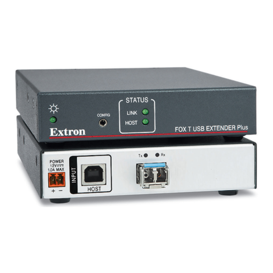
Page 17: Front Panel Features
Front Panel Features Transmitter Front Panel The transmitter has the following indicator LEDs and connector: STATUS LINK CONFIG HOST FOX T USB EXTENDER Plus A A A Power LED Host LED Config port Link LED Figure 5. Transmitter Front Panel Power LED —... -
Page 18: Receiver Front Panel
Receiver Front Panel The receiver has the following indicator LEDs and connector: STATUS LINK CONFIG HOST FOX R USB EXTENDER Plus A A A Power LED Hub LEDs Config port Link LED Host LED Figure 6. Receiver Front Panel Power LED — This green LED lights to indicate that the unit is receiving power. Config port —... -
Page 19: Cabling And Setup
Cabling and Setup Host Computer Keyboard SM or MM Fiber Cable Receiver Transmitter POWER POWER 1.0A MAX. 1.0A MAX. HOST OPTICAL OPTICAL Four female USB 2.0 compatible type A connectors provide +5 VDC at up to 500 mA to connected USB peripherals. Ground Ground +12 VDC... -
Page 20: Connecting The Fiber Optic Cable
Connect the provided external power supplies to the 2-pole captive screw power connectors on the transmitter and receiver. The front panel Power LED and Link LED and the rear panel Tx and Rx LEDs on both units light to indicate power is connected and a proper link cable connection exists between the transmitter and receiver. -
Page 21: Connecting For Serial Communication
Connecting for Serial Communication The front panel Config ports on both the transmitter and the receiver (see figure on page 9 and figure , on page 10) enable communication with a computer via an RS-232 connection. Connect a 9-pin D-to-2.5 mm cable from the host computer serial port to the Config port on either the transmitter or receiver front panel to enable serial communication (commands are sent to both units simultaneously). -
Page 22: Connecting Multiple Extenders To A Fox Matrix Switcher
Connect the LC SFP connector of a receiver to the LC SFP connector of the switcher. STATUS STATUS LINK LINK CONFIG CONFIG HOST HOST FAN ASSIMBLY FOX R USB EXTENDER Plus FOX T USB EXTENDER Plus FOX USB Extender Plus FOX USB Extender Plus Transmitter Receiver STATUS STATUS FAN ASSIMBLY LINK CONFIG LINK... -
Page 23: System Operation
System Operation No drivers are required for a host PC to function with the FOX T/R USB Extender Plus. The transmitter is detected by the operating system and appropriate USB device drivers are loaded. Certain USB peripherals, such as gaming keyboards, USB interactive whiteboards, scanners, printers, and similar devices, require specific drivers installed on the PC. -
Page 24: Remote Configuration And Control
Remote Configuration and Control This section describes the connection through which the FOX T/R USB Extender Plus can be configured and controlled remotely via SIS commands, and describes the commands that are available. The following topics are covered: • SIS Commands Host-to-Extender Communications •... -
Page 25: Extender-Initiated Messages
Extender-initiated Messages The extender sends the following copyright message when it first powers on: © Copyright 20nn, Extron Electronics FOX USB Extender Plus Series, Vn.nn, part number where is the firmware version number and part numbers are: Vn.nn FOX T USB Extender Plus MM — 60-1474-11 FOX T USB Extender Plus SM —... -
Page 26: Symbol Definitions
Symbol Definitions = CR/LF (carriage return and line feed) (hex 0D 0A } or = Soft carriage return (no line feed) ¦ • = Space E or = Escape key (hex = On and off (enable and disable) = Off or disabled = On or enabled = Extender unit part number: Transmitter: 60-1471-12... -
Page 27: Mounting
Mounting The 6 inches (15 cm) deep, 1 inch (2.5 cm) high, quarter-rack wide FOX T/R USB Extender Plus transmitter and receiver can be placed on a tabletop, mounted on a rack shelf, or mounted under a desk or tabletop. See the instructions in the individual mounting kits for installation instructions. - Page 28 Extron Electronics makes no further warranties either expressed or implied with respect to the product and its quality, performance, merchantability, or fitness for any particular use. In no event will Extron Electronics be liable for direct, indirect, or consequential damages resulting from any defect in this product even if Extron Electronics has been advised of such damage.
Need help?
Do you have a question about the FOX T USB and is the answer not in the manual?
Questions and answers