
Related Manuals for Extron electronics FOX T Plus MM


Summary of Contents for Extron electronics FOX T Plus MM
- Page 1 User Guide USB Extenders USER MANUAL FOX T/R USB Extender Plus Fiber Optic Extenders for USB Peripherals 68-2665-01 Rev. E 08 21...
- Page 3 Copyright © 2016-2021 Extron. All rights reserved. www.extron.com Trademarks All trademarks mentioned in this guide are the properties of their respective owners. The following registered trademarks ( ® ), registered service marks ( ), and trademarks ( ) are the property of RGB Systems, Inc. or Extron (see the current list of trademarks on the Terms of Use page at www.extron.com):...
- Page 4 FCC Class A Notice This equipment has been tested and found to comply with the limits for a Class A digital device, pursuant to part 15 of the FCC rules. The Class A limits provide reasonable protection against harmful interference when the equipment is operated in a commercial environment.
- Page 5 Class 1 Laser Product Any service to this product must be carried out by Extron and its qualified service personnel. CAUTION: Using controls, making adjustments, or performing procedures in a manner other than what is specified herein may result in hazardous radiation exposure. NOTE: For more information on safety guidelines, regulatory compliances, EMI/EMF compatibility, accessibility, and related topics, see the “Extron Safety and...
- Page 6 Conventions Used in this Guide Notifications The following notifications are used in this guide: Potential risk of severe injury or death. WARNING: AVERTISSEMENT : Risque potentiel de blessure grave ou de mort. CAUTION: Risk of minor personal injury. ATTENTION : Risque de blessure mineure.
-
Page 7: Table Of Contents
Contents Introduction Remote Configuration ............ 1 and Control ........... 17 About this Guide ..........1 About the FOX T/R USB Extender Plus ....2 SIS Commands ..........17 Host-to-Extender Communications ....17 Features ............. 2 Extender-initiated Messages ......18 USB System Architecture ........3 Error Responses .......... - Page 8 FOX T/R USB Extender Plus • Contents viii...
-
Page 9: Introduction
This user guide contains information needed to install, configure, and operate the Extron FOX T/R USB Extender Plus and the FOX T/R HID Only USB Extender Plus transmitter and receiver pairs. Additional product information can be found on the Extron Electronics website at www.extron.com. -
Page 10: About The Fox T/R Usb Extender Plus
About the FOX T/R USB Extender Plus The FOX T/R USB Extender Plus is a USB transmitter and receiver pair that extends USB signals over fiber optic cabling. It is compatible with USB 3.0, 2.0, 1.1, and 1.0 devices with transfer data rates up to 480 Mbps. -
Page 11: Usb System Architecture
Real-time status LED indicators for troubleshooting and monitoring — Provide • visual confirmation of port activity between an active host and each connected peripheral device. Extron FOX matrix switcher compatibility — Distributes signals up to 1000 x 1000 • and larger. •... - Page 12 Root Hub Tier 1 Built-in Hub Tier 2 Camera Tier 3 Speaker Tier 4 Tier 5 Tier 6 Compound Device = USB hub Keyboard Mouse Tier 7 = USB peripheral device Figure 1. Tiered Star Topology Example for a Computer with Four Monitors NOTE: Some computers include multiple hubs already connected to each other, occupying multiple tiers in the topology.
-
Page 13: Application Diagrams
Application Diagrams Extron FOX R USB Extender Plus Fiber Optic Receiver USB Touchscreen for USB Peripherals Display Extron FOX T USB Extender Plus Fiber Optic Transmitter for USB Peripherals T IC 1 .0 T IC 1 .0 Fiber M OT -2 32 U SB -2 32... - Page 14 Extron Extron FOXBOX SR HDMI FOX T USW 203 Fiber Optic Scaling Fiber Optic Switcher Receiver INPUTS OUTPUTS FOX T USW 203 HDMI OUTPUTS POWER RGB/R-Y, Y, B-Y REMOTE POWER HDMI AUDIO AUDIO AUDIO RS-232 HDMI RS-232 REMOTE 0.8A MAX OVER FIBER ALARM CONTACT...
-
Page 15: Installation And Operation
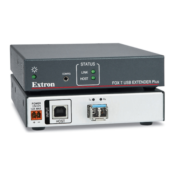
Installation and Operation This section describes how to connect and operate the FOX T/R USB Plus Extender. The following topics are covered: • Rear Panel Connections • Front Panel Features • Cabling and Setup • System Operation Troubleshooting • Rear Panel Features Transmitter Rear Panel The transmitter rear panel contains the following: E E E E E D D D D D... - Page 16 Power connector — Connect a provided 12 VDC external power supply to this 2-pole, 3.5 mm captive screw connector. ATTENTION: • The power supply must not be permanently fixed to the building structure or similar structures. • La source d’alimentation ne devra pas être fixée de façon permanente à une structure de bâtiment ou à...
-
Page 17: Receiver Rear Panel
Rx (link) LED — Lights steadily when a signal is passing between the transmitter Rx port and the receiver Tx port. Tx (link) LED — Lights steadily when a signal is passing between the transmitter Tx port and the receiver Rx port. The green Rx and Tx LEDs light and remain lit while a valid connection exists between the LC SFP connector of the transmitter and receiver and both units have power. -
Page 18: Front Panel Features
Front Panel Features Transmitter Front Panel The transmitter has the following indicator LEDs and connector: D D D STATUS LINK CONFIG HOST Extron FOX T USB EXTENDER Plus A A A A A B B B C C C Power LED Host LED Config port Link LED... -
Page 19: Receiver Front Panel
Receiver Front Panel The receiver has the following indicator LEDs and connector: D D D E E E STATUS LINK CONFIG HOST Extron FOX R USB EXTENDER Plus A A A A A B B B C C C Power LED Host LED Link LED Config port... -
Page 20: Cabling And Setup
Cabling and Setup Host Computer Keyboard SM or MM Fiber Cable Receiver Transmitter POWER POWER 1.0A MAX 1.0A MAX HOST OPTICAL OPTICAL Four female USB 3.0 compatible type A connectors provide +5 VDC at up to 500 mA to connected USB peripherals. Ground Ground +12 VDC... -
Page 21: Connecting The Fiber Optic Cable
Connect the provided external power supplies to the 2-pole captive screw power connectors on the transmitter and receiver. The front panel Power LED and Link LED and the rear panel Tx and Rx LEDs on both units light to indicate power is connected and a proper link cable connection exists between the transmitter and receiver. -
Page 22: Connecting For Serial Communication
Connecting for Serial Communication The front panel Config ports on both the transmitter and the receiver (see figure on page 10 and figure , on page 11) enable communication with a computer via an RS-232 connection. Connect a 9-pin D-to-2.5 mm cable from the host computer serial port to the Config port on either the transmitter or receiver front panel to enable serial communication. -
Page 23: Connecting Multiple Extenders To A Fox Matrix Switcher
Connecting Multiple Extenders to a FOX Matrix Switcher Multiple FOX T/R USB Plus Extenders can be connected to the inputs and outputs of an Extron FOX matrix switcher to route USB signals through the switcher. This connection enables each transmitter that is connected to a switcher input to send signals to one of the receivers that are attached to switcher outputs. -
Page 24: System Operation
System Operation No drivers are required for a host PC to function with the FOX T/R USB Extender Plus. The transmitter is detected by the operating system and appropriate USB device drivers are loaded. Certain USB peripherals, such as gaming keyboards, USB interactive white boards, scanners, printers, and similar devices, require specific drivers installed on the PC. -
Page 25: Remote Configuration And Control
Remote Configuration and Control This section describes the connection through which the FOX T/R USB Extender Plus can be configured and controlled remotely via SIS commands, and describes the commands that are available. The following topics are covered: • SIS Commands Host-to-Extender Communications •... -
Page 26: Extender-Initiated Messages
Extender-initiated Messages The extender sends the following copyright message when it first powers on: (C) Copyright 20nn, Extron Electronics FOX USB Extender Plus Series, Vn.nn, part number where is the year, is the firmware version number, and the are: 20nn Vn.nn... -
Page 27: Symbol Definitions
Symbol Definitions = CR/LF (carriage return and line feed) (hex 0D 0A ¦ } or | = Soft carriage return (no line feed) (hex • = Space E or = Escape key (hex = On and off (enable and disable) = Off or disabled = On or enabled = Extender unit part number:... -
Page 28: Mounting
Mounting The 6 inches (15 cm) deep, 1 inch (2.5 cm) high, quarter-rack wide FOX T/R USB Extender Plus transmitter and receiver can be placed on a tabletop, mounted on a rack shelf, or mounted under a desk or tabletop. See the instructions in the individual mounting kits for installation instructions. - Page 29 Extron Warranty Extron warrants this product against defects in materials and workmanship for a period of three years from the date of purchase. In the event of malfunction during the warranty period attributable directly to faulty workmanship and/ or materials, Extron will, at its option, repair or replace said products or components, to whatever extent it shall deem necessary to restore said product to proper operating condition, provided that it is returned within the warranty period, with proof of purchase and description of malfunction to: USA, Canada, South America,...
Need help?
Do you have a question about the FOX T Plus MM and is the answer not in the manual?
Questions and answers