Advertisement
Table of Contents
DTP HDMI 301 • Setup Guide
This guide provides quick start instructions for an experienced installer to set up and operate
Extron DTP HDMI 301 digital video extender. The DTP 301 transmitter and receiver pair can
extend an HDCP-compliant HDMI signal up to 330 feet (100 m).
Installation
Step 1 — Mounting
Turn off or disconnect all equipment power sources and mount the Tx and Rx units as required.
DTP HDMI 301 Tx Rear Panel
DTP HDMI 301 Tx Rear Panel
INPUTS
POWER
12V
0.6 A MAX
7
1
Step 2 — Connections
a
HDMI Input connector (Tx) — Connect an HDMI cable
between this port and the HDMI output port of the digital
video source.
b
Audio input (Tx) — Connect an unbalanced stereo audio
source to this 3.5 mm mini stereo jack for an analog audio
input.
c
RS-232 and IR connectors — To pass serial or infrared data or control signals, such as
serial control of a projector, connect the master device to the transmitter and the slave
device to the receiver via the RS-232 and IR captive screw connectors on both units.
d
DTP and Analog Audio (Output and Input) RJ-45 connectors — Connect one or
two TP cables between these RJ-45 female connectors on the transmitter and receiver.
Ü
DTP connector (required) — Connect transmitter DTP Out to receiver DTP In.
This cable carries:
TMDS (digital) video
z
Embedded audio
z
Bidirectional RS-232 and IR commands and data
z
Remote power
z
Signal LED — This LED lights when the unit is receiving a TMDS clock signal on the
HDMI input (transmitter) or any valid signal on the DTP In connector (receiver).
Link LED — This LED lights a valid link is established between the units on the DTP
cable.
á
Analog Audio connector (optional) — Connect transmitter Analog Audio Out to receiver Analog Audio In. This cable
carries analog audio only and is not needed for applications that do not require this audio signal.
Terminate all cable ends in accordance with the same standard, either TIA/EIA T 568 A or TIA/EIA T 568 B.
CAUTION:
Do not connect these devices to a computer data or telecommunications network.
NOTES:
•
The DTP and Analog Audio ports are in reverse order on the receiver.
•
You can check the DTP Out to DTP In cable connection as follows:
1. Plug a cable into the DTP jack on the powered unit.
2. Connect the opposite end of the cable into the DTP jack on the unpowered unit.
If the DTP Link LED and the Power LED on the unpowered unit are lit, the connection is correct.
OUT
SIG
LINK
AUDIO
RS-232
DTP OUT
Tx
Rx
ANALOG AUDIO
2
4
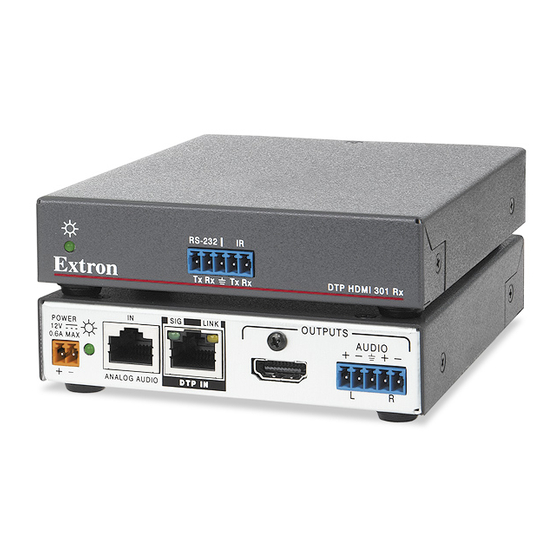
DTP HDMI 301 Rx Rear Panel
DTP HDMI 301 Rx Rear Panel
POWER
12V
0.6 A MAX
IR
Tx
Rx
3
7
INPUTS
IN
SIG
LINK
DTP IN
ANALOG AUDIO
4
5
Front Panel
Front Panel
Front Panel
RS-232
IR
AUDIO
Tx
Rx
Tx
Rx
3
Tx/Rx
Pins
Pins:
12345678
TP Wires
OUTPUTS
AUDIO
L
R
6
DTP HDMI 301 Rx
Connected RS-232
and IR Device Pins
Transmit pin on connected unit
Receive pin on connected unit
Ground
Transmit pin on connected unit
Receive pin on connected unit
TIA/EIA T
TIA/EIA T
568 A
568 B
Pin
Wire color
Wire color
1
White-green
White-orange
Orange
2
Green
3
White-orange
White-green
4
Blue
Blue
5
White-blue
White-blue
Green
6
Orange
7
White-brown
White-brown
8
Brown
Brown
Advertisement
Table of Contents

Related Manuals for Extron electronics DTP HDMI 301


Summary of Contents for Extron electronics DTP HDMI 301
- Page 1 This guide provides quick start instructions for an experienced installer to set up and operate Extron DTP HDMI 301 digital video extender. The DTP 301 transmitter and receiver pair can extend an HDCP-compliant HDMI signal up to 330 feet (100 m).
- Page 2 DTP HDMI 301 • Setup Guide (Continued) HDMI Output connector (Rx) — Connect a display with an HDMI input for display of the OUTPUTS AUDIO transmitted direct digital image. Audio Output connector (Rx) — Connect a balanced or unbalanced stereo or mono audio device to the receiver via the Audio captive screw connector.
Need help?
Do you have a question about the DTP HDMI 301 and is the answer not in the manual?
Questions and answers