Extron electronics FOX3 T 301 User Manual
Fiber optic extenders, fiber optic hdmi transmitters and receivers
Hide thumbs
Also See for FOX3 T 301:
- Setup manual (4 pages) ,
- Setup manual (4 pages) ,
- Setup manual (4 pages)

Related Manuals for Extron electronics FOX3 T 301


Summary of Contents for Extron electronics FOX3 T 301
- Page 1 User Guide Fiber Optic Extenders FOX3 T/R 301 FOX3 T/R 311 Fiber Optic HDMI Transmitters and Receivers 68-2711-01 Rev. A 04 20...
- Page 2 Safety Instructions Safety Instructions • English Istruzioni di sicurezza • Italiano AVVERTENZA: Il simbolo, , se usato sul prodotto, serve ad WARNING This symbol, , when used on the product, is intended avvertire l’utente della presenza di tensione non isolata pericolosa to alert the user of the presence of uninsulated dangerous voltage all’interno del contenitore del prodotto che può...
- Page 3 Copyright © 2020 Extron Electronics. All rights reserved. www.extron.com Trademarks All trademarks mentioned in this guide are the properties of their respective owners. The following registered trademarks ( ® ), registered service marks ( ), and trademarks ( ) are the property of RGB Systems, Inc. or Extron Electronics (see the Terms of Use www.extron.com):...
- Page 4 Débarrassez-vous des piles usagées selon le mode d’emploi. Class 1 Laser Product Any service to this product must be carried out by Extron Electronics and its qualified service personnel. CAUTION: Using controls, making adjustments, or performing procedures in a manner other than what is specified herein may result in hazardous radiation exposure.
- Page 5 Conventions Used in this Guide Notifications The following notifications are used in this guide: DANGER: • Will result in serious injury or death. • Entraînera des blessures graves ou la mort. WARNING: Potential risk of severe injury or death. AVERTISSEMENT : Risque potentiel de blessure grave ou de mort. CAUTION: Risk of minor personal injury.
-
Page 7: Table Of Contents
Contents Introduction ..........1 SIS Configuration and Control ....23 About this Guide ..........1 Host Control Ports ..........23 Product Description ..........1 Rear Panel RS-232 Port ........ 23 Transmitter............3 Front Panel Configuration USB Port ....23 Receiver ............3 Ethernet (LAN) Ports ........ - Page 8 Equipment Mounting ......... 49 Mounting the Transmitter ........49 Tabletop Use ..........49 Mounting kits ..........49 UL Rack-Mounting Guidelines ....... 49 FOX3 T/R 301/311 Transmitters and Receivers • Contents viii...
-
Page 9: Introduction
Introduction The FOX3 T/R 301 and FOX3 T/R 311 output continuous invisible light WARNING: (Class 1 rated), which may be harmful to the eyes; use with caution. AVERTISSEMENT : Le FOX3 T/R 301 et FOX3 T/R 311 émet une lumière invisible en continu (conforme à la classe 1) qui peut être dangereux pour les yeux, à utiliser avec précaution. - Page 10 Extron FOX3 T 301 Fiber Optic Transmitter Ethernet R S- R S- 0. 7A D IO 0- 24 HDMI -6 0 Loop out HDMI Input Up to 20 km (12.43 miles) Singlemode Fiber SM Model Extron XPA 1002 Local Power Ampli er...
-
Page 11: Transmitter
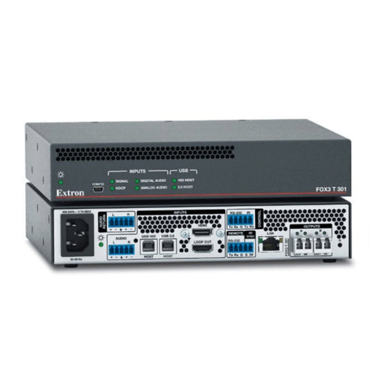
Transmitter The FOX3 T 301 and FOX3 T 311 transmitters accept HDMI video, at a resolution of up to 4K (4096x2160 @ 60 Hz). The video input can also include embedded audio. The transmitter also loops the HDMI input through for a local monitor. The transmitter can accept an analog audio input on a 5-pole captive screw connector. -
Page 12: Fiber Cable Transmission Modes
SFP module, enabling the highest video performance. Features • FOX3 T 301 — Transmits HDMI video, USB HID, USB 2.0, stereo audio, RS-232 control, IR control, and 3D sync signals over fiber optic cabling. • FOX3 T 311 — Transmits HDMI video, USB HID, stereo audio, RS-232 control, IR control, and 3D sync signals over fiber optic cabling. - Page 13 HDMI audio de-embedding with analog stereo outputs (FOX3 receivers) — • Digital HDMI audio is made available as a balanced or unbalanced analog stereo signal on captive screw connectors. • Key Minder continuously verifies HDCP compliance for quick, reliable switching — Authenticates and maintains continuous HDCP encryption between input and output devices to ensure quick and reliable switching in professional AV environments.
- Page 14 Internal color bars test pattern for calibration and setup — Simplifies setup and • installation by providing a video signal when a source is unavailable. Compatible with Extron FOX3 Series matrix switchers — Creates HDCP- • compliant signal distribution systems. •...
-
Page 15: Installation And Operation
Installation and Operation This section details the installation of the FOX3 T/R 301/311 transmitter and receiver system, including: • Installation Overview • Rear Panel Features • Front Panel Features • Connector and Cable Details Operation • Installation Overview Follow these steps to install and set up an Extron FOX3 T/R 301/311 transmitter and receiver system for operation: Turn off all of the equipment. - Page 16 Power inlet (see figure 2 on page 7) — Plug a standard IEC power cord into this connector to connect the unit to a 100 VAC to 240 VAC, 50-60 Hz power source. Power LED — The lit LED indicates power is applied and device is ready to transmit. Audio Return —...
- Page 17 SFP module and LEDs — (see figure 2 on page 7) WARNING: The units output continuous invisible light (Class 1 rated), which may be harmful to the eyes; use with caution. Plug the attached dust cap into the optical transceiver when the fiber optic cable is unplugged. AVERTISSEMENT : Le produit émet une lumière invisible en continu (conforme à...
-
Page 18: Receiver Rear Panel Connections
Receiver Rear Panel Connections NOTE: Figure 4 shows the FOX3 R 301 receiver. The FOX3 R 311 looks similar, with the exception of the USB ports ( ). It has no USB 2.0 port. 100-240V 0.7A MAX OUTPUTS RS-232 DEVICES Tx Rx Tx Rx INPUTS USB HID... - Page 19 Remote RS-232/3D Sync port — (see figure 4 on page 10) • Remote RS-232 port — For serial control of the receiver, connect a host device, such as a computer or touch panel control, via the three left poles (Tx, Rx, and G) of this 5-pole captive screw connector (see RS-232, IR, and Sync Connectors page 14 to wire this connector).
- Page 20 — SFP module and LEDs WARNING: The devices output continuous invisible light (Class 1 rated), which may be harmful to the eyes; use with caution. Plug the attached dust cap into the optical transceiver when the fiber optic cable is unplugged. AVERTISSEMENT : Le produit émet une lumière invisible en continu (conforme à...
-
Page 21: Connector And Cable Details
Connector and Cable Details HDMI Connectors HDMI signals run at a very high frequency and are especially prone to errors caused by bad video connections, too many adapters, or excessive cable length. To avoid the loss of an image or jitter, follow these guidelines: Limit or avoid the use of adapters. -
Page 22: Analog Audio Connectors
Analog Audio Connectors See figure 7 to wire connectors for the appropriate input and output type for the analog audio and audio return audio. Connectors are included with the transmitter and receiver, but you must supply the audio cable. Use the supplied tie-wraps to strap the cable to the extended tail of the connectors. -
Page 23: Tp Cable Termination And Recommendations
TP Cable Termination and Recommendations It is vital that your Ethernet cable be the correct cable type and that it be properly terminated with the correct pinout. Ethernet links use Category (CAT) 3, 5e, or CAT 6, unshielded twisted pair (UTP) or shielded twisted pair (STP) cables, terminated with RJ-45 connectors. Ethernet cables are limited to a length of 328 feet (100 meters). -
Page 24: Usb Hid And Usb 2.0 Connectors
USB HID and USB 2.0 Connectors NOTES: The FOX3 matrix switches the USB HID and USB 2.0 inputs and outputs • independently of the video and each USB connection. • The USB 2.0 port is only available on the FOX3 T/R 301 devices. •... -
Page 25: Front Panel Features
). The FOX3 T/R 311 have no USB 2.0 LEDs. INPUTS DIGITAL AUDIO SIGNAL HID HOST CONFIG HDCP ANALOG AUDIO 2.0 HOST FOX3 T 301 INPUT HOST SIGNAL USB HID CONFIG HDCP USB 2.0 FOX3 R 301 Figure 11. Transmitter and Receiver Front Panel Features Power LED —... -
Page 26: Operation
Operation After the transmitter, receiver, and the connected devices are powered up, the system is fully operational. If any problems are encountered, ensure all cables are routed and connected properly. NOTE: Ensure that the video source and display are properly connected to the FOX3 pair, and power is applied FOX3 pair and the display before power is applied to the video source. - Page 27 Reset Modes Mode Activation Result Purpose and Notes Hold in the recessed rear panel The device reverts to the factory default Use mode 1 to revert to Reset button while applying firmware for a single power cycle. the factory default firmware power to the unit.
-
Page 28: Configuration
Configuration NOTE: Transmitters and receivers can be configured via PCS (see the FOX3 T/R 301 and FOX3 T/R 311 Help File) and SIS commands (see SIS Configuration and Control starting on page 23). Product help files are available in PCS when a device is connected or an offline device is selected. EDID The FOX3 uses EDID Minder, which ensures that a source device connected to the transmitter input continuously sees the EDID of a sink device, even if the sink is not... -
Page 29: Insertion
Tx Rx S 5V 60-60 Hz 100 mA 500 mA HDMI Tx Rx S 5V 60-60 Hz Extron Extron FOX3 T 301 FOX3 R 301 Fiber Optic Transmitters Fiber Optic Receiver RS-232 HDMI Projector RS-232 HDMI Laptop COM 1 COM 2... -
Page 30: Audio Configuration
Audio Configuration Audio Embedding The FOX3 supports a single audio signal to pass LPCM-2CH. • Transmitter — The audio input sent over the fiber output can be configured via PCS (see the FOX3 T/R 301 and FOX3 T/R 311 Help File) or SIS command (see Input audio selection on page 31). -
Page 31: Sis Configuration And Control
SIS Configuration and Control This section describes the remote control operation of the FOX3 T/R 301/311 transmitter and receiver, including: • Host Control Ports • Simple Instruction Set Control • Command and Response Table for SIS Commands The FOX3 transmitters and receivers can be configured using SIS commands, PCS, or embedded web pages. -
Page 32: Ethernet (Lan) Ports
Ethernet (LAN) Ports figure 2 figure 4 The rear panel Ethernet connector (see on page 7 and on page 10) can be connected to an Ethernet LAN or WAN. Communications between the transceiver and the controlling device is via an SSH client such as PuTTY using port 22023. This connection makes SIS control of the unit possible using a computer connected to the same LAN or WAN (see TP Cable Termination and Recommendations... - Page 33 Figure 15. PuTTY Security Alert Window If this is a trusted host or device, click the Yes button (see figure 16, ). The connection is made and the host or device is added to the PuTTY cache. If this is a one‑time connection, click the No button ( ).
-
Page 34: Simple Instruction Set Control
A string is one or more characters. Device-Initiated Power-Up Message When the device completes its start‑up, it issues the following message to the host: © Copyright 20yy, Extron Electronics FOX3 T (R) 301 (311) MM (SM), Vx.xx, 60‑nnnn‑nn Vx.xx is the firmware version number •... -
Page 35: Timeout
Timeout Pauses of 10 seconds or longer between command ASCII characters result in a timeout. The command operation is aborted with no other indication. Using the Command and Response Table The command and response table begins below. Symbols are used throughout the table to represent variables in the command and response fields. -
Page 36: Common Symbol Definitions
Common symbol definitions Carriage return/line feed space • } or Carriage return (no line feed) or W = Escape key 0 = Unmute (default) 1 = Mute video only = Video mute 2 = Mute video and sync = Audio output 1 = Digital (Tx Loop Out or Rx HDMI Out) 2 = Analog (Tx Return Out or Rx Analog Output) 3 = All outputs (digital and return/analog) -
Page 37: Command And Response Table For Sis Commands
Command and Response Table for SIS Commands SIS Command Response Additional description Command Function (Host to Unit) (Unit to Host) Transmitter and Receiver Video mute Mute output video only Vmt1 Mute output video and sync Vmt2 Unmute video and sync Default Vmt0 View mute status... - Page 38 SIS Command Response Additional description Command Function (Host to Unit) (Unit to Host) Transmitter and Receiver (continued) Information requests (continued) Information request X& X2(] SFPALnk SFPBLnk SigI HdcpI HdcpO AudI • • • • • • • Verbose mode 2/3: X&...
- Page 39 SIS Command Response Additional description Command Function (Host to Unit) (Unit to Host) Transmitter and Receiver (continued) RS-232 COMM settings EX1^ X1%] Set serial port parameters • 15200 9600 default) KEY: = Baud rate − baud ( = Parity ven, one (default), ark, pace (only the first letter required)
- Page 40 SIS Command Response Additional description Command Function (Host to Unit) (Unit to Host) Transmitter only (common) (continued) Input signal detection information View detected input signal 35I/i X2#] •AudI •VcsI •Pixcl information Inf35* Res X2# ] Verbose mode 2/3: •AudI •VcsI •Pixcl KEY: = Input HDCP Authorization...
-
Page 41: Configuration Software
Configuration Software The FOX3 301/311 transmitters and receivers can be easily configured using Extron Product Configuration Software (PCS). This section describes the software installation and communication (see the FOX3 T/R 301/311 PCS Help File for detailed control information). The topics covered in this section are: Software/Firmware Installation •... - Page 42 Scroll down to the alphabetic navigation bar (see figure 18). Figure 18. Software Installation Click the appropriate letter to locate the software or firmware. Click Download and follow the on-screen instructions (see figure 19, for PCS). Figure 19. PCS Software Download For Firmware: Figure 20.
-
Page 43: Connecting To Pcs
Connecting to PCS The Extron Product Configuration Software window opens with the Device Discovery panel open. Connect to the device using the Device Discovery panel or the TCP/IP panel (see figure 21). Device Discovery Panel The Device Discovery panel displays accessible Extron devices connected directly to the PC or to a LAN or WAN. -
Page 44: Tcp/Ip Panel
TCP/IP Panel The TCP/IP panel connects PCS to a specific device through Ethernet. Figure 23. Comm Port Selection Windows Click the TCP/IP tab (see figure 23, In the IP Address/Hostname field ( ), enter the IP address of the desired device. NOTE: If the IP address has not been changed, it is 192.168.254.254. -
Page 45: Software Overview
The New Configuration File dialog box opens (see figure 25). Figure 25. New Configuration File Dialog Box Select the desired device model from the Device Models list (see figure 25). Click the Configure button. A new offline device configuration tab opens. Software Overview NOTE: For details about specific software features, see the FOX3 T/R 301/311 PCS Help File. -
Page 46: Software Menu
Software Menu The Software menu (see figure 27) contains options pertaining to PCS settings. Figure 27. PCS Software Menu Show Expanded Device Tabs Selecting Show Expanded Device Tabs from the Software menu displays the device IP address or connection method in the Device tab. Figure 28. - Page 47 About Extron PCS Display information about the current PCS version. From the Software menu, select About Extron PCS. The About - Extron PCS dialog box opens. Figure 30. About - Extron PCS Dialog Box Click the Details button (see figure 30, ) for more information.
-
Page 48: Device Menu
Device Menu The Device menu contains options pertaining to device connection, configuration, and information. For details about all these options, see the FOX3 T/R 301/311 PCS Help File. Figure 32. Device Menu • Disconnect — Disconnect the device from the PCS program and close the Device tab. - Page 49 Update Firmware — Open a submenu to upload firmware from the host device to the • connected device or to multiple devices. NOTE: If necessary, download new firmware from the Extron website (see Software/Firmware Installation on page 33). • Update Firmware to this Device... — Upload firmware from the host device to the connected device only.
-
Page 50: Internal Web Page
Internal Web Page The FOX3 301 and 311 transmitters and receivers feature an internal web server, displayed as a web page. This page allows you to monitor and adjust certain settings of the FOX3 301 and 311 devices via a LAN or WAN connection. Use a web browser to view the pages on a PC connected to the device LAN port. -
Page 51: Disabling Compatibility Mode
Disabling Compatibility Mode ® The internal web page does not support compatibility mode in Microsoft Internet Explorer ® . To check compatibility view settings: From the Tools menu of the browser, select Compatibility View Settings. The Compatibility View Settings dialog box opens. Be sure the Display all websites in Compatibility View checkbox is clear, and the IP address of the scaler is not in the list of websites that have been added to Compatibility View. -
Page 52: Device Status Panel
To change the name: ) in the Device Info panel. The Device Info Click EDIT (see figure 35 [left], Settings panel opens to allow edits (right). Figure 35. Device Info Panel Edit the Device Name as desired. When finished editing, click SAVE to confirm your changes or CANCEL to close the window without making changes. -
Page 53: Network Settings Panel
Network Settings Panel In the Network Settings panel (see figure 34, on page 43), set the IP address, subnet mask, and gateway address for your FOX3, and turn DHCP On and Off. To set the IP addresses: Click EDIT (see figure 37 [left], ) in the Network Settings panel. -
Page 54: Roles And Permissions Panel
NOTE: Firmware files for FOX3 T/R 301/311 have a .eff extension. Do not attempt to load any other file types. Double-click the firmware file name. The Open window closes, and the selected firmware file name appears in the Update Firmware panel on the web page. -
Page 55: Linklicense Panel
When finished, click SAVE to set the passwords. To close the window without saving a password, click CANCEL or the X in the upper-right corner. Passwords can be changed but they cannot be removed entirely. The FOX3 must have a passwords at all times. These fields cannot be blank. -
Page 56: About The Fox3 T/R 301/311
About the FOX3 T/R 301/311 Click on the ABOUT link (see figure 34, on page 43) to open the About dialog box to view general information about the FOX3 T/R 301/311, such as the firmware version, copyright, part number, licenses, patents and web page version. Click on the View the End User License Agreement link to view the user license. - Page 57 Equipment Mounting This section provides procedures for mounting the FOX3 T/R 301/311 Transmitters and Receivers. Mounting the Transmitter ATTENTION: Installation and service must be performed by authorized personnel only. • • L’installation et l’entretien doivent être effectués par le personnel autorisé uniquement. The 1-inch high, half rack width transmitter can be placed on a table, mounted in a rack, or mounted under a desk or table.
- Page 58 Extron Electronics makes no further warranties either expressed or implied with respect to the product and its quality, performance, merchantability, or fitness for any particular use. In no event will Extron Electronics be liable for direct, indirect, or consequential damages resulting from any defect in this product even if Extron Electronics has been advised of such damage.
Need help?
Do you have a question about the FOX3 T 301 and is the answer not in the manual?
Questions and answers