Table of Contents
Advertisement
Quick Links
Download this manual
See also:
User Manual
Advertisement
Table of Contents

Related Manuals for Extron electronics FOXBOX Tx HDMI


Summary of Contents for Extron electronics FOXBOX Tx HDMI
- Page 1 User Guide Fiber Optic Extenders FOXBOX Tx / Rx HDMI High Resolution Fiber Optic Transmitters and Receivers 68-1984-01 Rev. A 05 12...
- Page 2 Safety Instructions • English Warning Power sources • This equipment should be operated only from the power source indicated on the product. This This symbol is intended to alert the user of important operating and mainte- equipment is intended to be used with a main power system with a grounded (neutral) conductor. The third nance (servicing) instructions in the literature provided with the equipment.
- Page 3 FCC Class A Notice This equipment has been tested and found to comply with the limits for a Class A digital device, pursuant to part 15 of the FCC Rules. Operation is subject to the following two conditions: This device may not cause harmful interference. This device must accept any interference received, including interference that may cause undesired operation.
- Page 4 Selectable items, such as menu names, menu options, buttons, tabs, and field names are written in the font shown here: From the File menu, select Click the button. Copyright © 2012 Extron Electronics. All rights reserved. Trademarks All trademarks mentioned in this guide are the properties of their respective owners.
-
Page 5: Table Of Contents
Contents Introduction Remote Control ............1 ........... 17 About this Guide ..........1 Simple Instruction Set Control ......18 About the FOXBOX Tx/Rx HDMI ......2 Host-to-Unit Instructions ....... 18 Transmitter ............2 Symbol Definitions ........18 Receiver ............2 Unit-initiated Messages ......... - Page 6 FOXBOX Tx/Rx HDMI • Contents...
-
Page 7: Introduction
HDMl TCP/IP T IC -2 3 F IB Extron D IO Extron ® 1 .0 FOXBOX Tx HDMI SI 26X Two-way Ceiling Fiber Optic Transmitter Speakers HDMI Up to 30 km (18.75 miles) singlemode ber SM Model IN G W IR... -
Page 8: About The Foxbox Tx/Rx Hdmi
The bidirectional Consumer Electronics Control (CEC) is not supported. Transmitter The FOXBOX Tx HDMI transmitter accepts HDMI video or DVI-D video (with an applicable adapter), at resolutions up to 1920 x 1200 at 60 Hz. The video input can also include embedded audio. -
Page 9: Both Units
RS-232 Simple Instruction Set (SIS™) control. Both units have image, audio, fiber light status, and lost-light alarm indicators. System Compatibility The FOXBOX Tx HDMI transmitter operates in either of two modes, selected under RS-232 control, for compatibility with other, non-HDMI, units: •... -
Page 10: Features
Loop-through on transmitter — The transmitter has an HDMI loop-through on a HDMI connector that allows connection of a local monitor. EDID emulation mode (Display Data Channel [DDC]) — The FOXBOX Tx HDMI transmitter provides a selector switch for specifying the rate of the incoming digital video signal. -
Page 11: Installation And Operation
DVI-D (with the appropriate adapter) to this HDMI connector (see “HDMI on page 12 for pin assignments). The FOXBOX Tx HDMI also accepts embedded digital audio on this connector. HDMI Loop-through connector — If desired, connect a local monitor to this HDMI connector. - Page 12 Audio connector — Plug an audio input into the transmitter via this stereo mini jack connector. NOTE: See figure 3 to identify the tip, ring, and sleeve when you are making connections for the transmitter from existing audio cables. A mono audio connector consists of the tip and sleeve.
- Page 13 Fiber optic connectors and LEDs — CAUTION: These units output continuous invisible light, which may be harmful to the eyes; use with caution. For additional safety, plug the attached dust caps into the optical transceivers when the fiber cable is unplugged. NOTES: •...
- Page 14 Control“ on page 17 for SIS commands and software control. cable. See “Remote The TRS RS-232 cable is included with the FOXBOX Tx HDMI transmitter. DC power connector — Plug the included external 12 VDC power supply into this “Power supply wiring“...
-
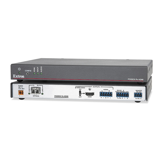
Page 15: Receiver Connections, Controls, And Indicators
Receiver Connections, Controls, and Indicators Rear panel POWER OUTPUTS HDMI AUDIO AUDIO RS-232 REMOTE 1.0A MAX OVER FIBER ALARM RS-232 FOXBOX Rx HDMI HDMI OPTICAL Tx Rx Tx Rx Figure 4. FOXBOX Rx Receiver Rear Panel Features HDMI Output connector — Connect a video display to this HDMI connector. See “HDMI connector“... - Page 16 Fiber optic connectors and LEDs — CAUTION: These units output continuous invisible light, which may be harmful to the eyes; use with caution. For additional safety, plug the attached dust caps into the optical transceivers when the fiber cable is unplugged. NOTES: •...
-
Page 17: Front Panel
14 for more details on the adapter cable. See “Remote Control“ on page 17 for SIS commands and software control. The TRS RS-232 cable is included with the FOXBOX Tx HDMI transmitter. FOXBOX Tx/Rx HDMI • Installation and Operation... -
Page 18: Making Connections
Making Connections HDMI connector Figure 8 defines the HDMI pin assignments. HDMI HDMI Type A Receptacle Type A Plug Signal Signal Signal TMDS data 2+ TMDS data 0– CEC control TMDS data 2 TMDS data 0 Reserved shield shield (NC) TMDS data 2- TMDS data 0- TMDS data 1+... - Page 19 Place the LockIt lacing bracket on the screw and against the HDMI connector, then tighten the screw to secure the bracket ( ATTENTION: Do not overtighten the HDMI connector mounting screw. The shield to which it fastens is very thin and can easily be stripped. Loosely place the included tie wrap around the HDMI connector and the LockIt lacing bracket as shown ( While holding the connector securely against the lacing bracket, use pliers or similar...
- Page 20 Audio output connector See figure 12 to properly wire a captive screw output connector. The connector is included with transmitter, but you must supply the audio cable. Use the supplied tie-wrap to strap the audio cable to the extended tail of the connector. NO GROUND HERE Ring Sleeves...
-
Page 21: Power Supply Wiring
Control“ on page 17 for definitions of the SIS commands (serial commands “Remote to control the transmitter via this connector) and software control. Power supply wiring ATTENTION: Always use power supplies specified by Extron for the FOXBOX units. Use of an unauthorized power supply voids all regulatory compliance certification and may cause damage to the supply and the unit. -
Page 22: Operation
Use the supplied tie wrap to strap the power cord to the extended tail of the connector. Alternatively, an optional Extron PS 124 Universal 12 VDC Power Supply, part #60-1022-01, can power multiple Extron 12 VDC devices using only one AC power connector. Operation After the transmitter, all receivers, and their connected devices are powered up, the system is fully operational. -
Page 23: Remote Control
Remote Control This section describes the remote control operation of the FOXBOX HDMI and, including: • Simple Instruction Set Control FOX Extenders Control Program • The transmitter and receiver each have a front panel Configuration port, a 2.5 mm “Front panel Configuration Ports“... -
Page 24: Simple Instruction Set Control
Simple Instruction Set Control Host-to-Unit Instructions SIS commands consist of one or more characters per field. No special characters are required to begin or end a command character sequence. When a command is valid, the unit executes the command and sends a response to the host device. All responses from the unit to the host end with a carriage return and a line feed (CR/LF = ] ), which signals the end of the response character string. -
Page 25: Unit-Initiated Messages
When a local event, such as an equipment power-up, occurs, the unit responds by sending a message to the host. The unit-initiated messages are listed below: (c) Copyright 20nn, Extron Electronics FOXBOX Tx HDMI, Vx.xx, 60-1174-xx ]] - or - (c) Copyright 20nn, Extron Electronics FOXBOX Rx HDMI, Vx.xx, 60-1174-xx ]]... - Page 26 Command/Response Table for Transmitter SIS Commands Command ASCII Command Response Additional description (host to unit) (unit to host) Switch status Request EDID and refresh Stat EdidMdr •Vrate rate switch positions Stat EdidMdr15•Vrate2 Example: EDID switch is set to 15 (1080p) and the vertical rate switch is set to 2 (60 Hz).
- Page 27 Command/response table for Transmitter SIS commands (continued) Command ASCII Command Response Additional description (host to unit) (unit to host) Audio input gain and attenuation NOTES: • The set gain (G) and set attenuation (g) commands are case sensitive. The increment level, decrement level, and show level are not case sensitive.
- Page 28 Command/response table for Transmitter SIS commands (continued) Command ASCII Command Response Additional description (host to unit) (unit to host) Information requests Information request 1Lnk • 2Lnk • • • • The unit responds with the current status (signal detected) of optical link 1, optical link 2, the video input, and the audio link;...
- Page 29 Symbol definitions for receiver SIS commands = Carriage return/line feed = Carriage return (no line feed) = Pipe (can be used interchangeably with the character) • = Space (hard) character = Escape key (hex 1B) = Can be used interchangeably with the character = Mute/auto memory status and enable or disable status 0 = off or disable...
- Page 30 Command/response table for Receiver SIS commands (continued) Command ASCII Command Response Additional description (host to unit) (unit to host) Memory presets X1*] Save preset Command code is a comma. X1*] Recall preset Command code is a period. Auto memory Disable auto memory 55*0# Img0 Enable auto memory...
- Page 31 Command/response table for Receiver SIS commands (continued) Command ASCII Command Response Additional description (host to unit) (unit to host) Video shutdown delay NOTES: • The Set Video Delay command delays the digital video to help monitors sync correctly during an input rate change. •...
-
Page 32: Fox Extenders Control Program
Launch.exe from the DVD. Click the Software tab, scroll to the desired program, and click Install. Follow the instructions that appear on the screen. By default, the installation creates a C:\Program Files\Extron\FOX_Extenders directory, and it places four icons into a group folder named “Extron Electronics\FOX Extender Control Program” The four installed icons are: •... -
Page 33: Starting The Program
Starting the Program Start the Extron FOX Extenders program as follows: Click Start > Programs > Extron Electronics > FOX Extenders Control Program > FOX Extenders. The Communication Setup window appears (see figure 15). Figure 15. Communication Setup Window Select the Com port to which your transmitter or receiver is connected. Click OK. The FOX Extenders Control Program window appears (see figure 16). - Page 34 Status area Figure 17. Status Area The status area provides indications of the connection status. HDMI indicator — This indicator is green when the transmitter detects a sync signal on • its HDMI video input • Audio indicator — This indicator is green when the transmitter detects a low level audio signal for a short period.
- Page 35 Audio Adjustment area NOTE: The Audio Adjustment area controls are available only if you are connected to the transmitter. Audio Gain/Attenuation slider — Click and drag the Audio Gain/ Attenuation slider control to select the input audio gain or attenuation value, from -18 dB to +10 dB in 1.0 dB increments.
- Page 36 HDCP area NOTE: • The HDCP Authorized controls are available only if you are connected to the transmitter. • The HDCP Notification controls are available only if you are connected to the receiver. Both sets of radio buttons cannot be available for selection at the same time.
- Page 37 Video Bit Depth area NOTE: The Video Bit Depth area radio buttons are available only if you are connected to the receiver. The Video Bit Depth radio buttons allow you to force the bit depth to 8 bits or to set it to auto.
-
Page 38: Firmware Upgrade
Firmware upgrade Firmware can be upgraded for each unit via the front panel Configuration port on that unit using the Extron Firmware Loader utility from the Windows-based control program. NOTE: Your computer must be connected directly to the unit for the firmware to be updated. - Page 39 Follow the instructions on the rest of the download screens to download the firmware update from the Extron Web site, start the Extron Installation Program to extract the firmware file, and place it in a folder identified in the program window. NOTE: Note the folder to which the firmware file is saved (see figure 21).
- Page 40 If you have not previously updated firmware for the FOXBOX unit before, on the Add Device screen (see figure 22), select the RS-232 tab. Figure 22. Add Device Screen If you have previously updated firmware for this model, click Cancel. The Firmware Loader window appears.
- Page 41 Navigate to and select the new firmware file. Click Open. The Choose Firmware File window closes. NOTE: When downloaded from the Extron Web site, the firmware is placed in a subfolder of C: \Program Files\Extron\Firmware. ATTENTION: The firmware file must have a .S19 extension. Other file types can cause the unit to stop functioning.
-
Page 42: Reference Information
Reference Information This section discusses the specifications, part numbers, and accessories for the FOXBOX Tx/Rx HDMI. Topics that are covered, include: Specifications • • Part Numbers Mounting the Units • Specifications NOTES: • The analog audio signal(s) is (are) digitized in the transmitter, sent through the fiber cable, and converted back to analog audio in the receiver. -
Page 43: Video Output
Video NOTE: *Appropriate HDMI to DVI-D cables or adapters are required for DVI signal input/output. Resolution range ......Up to 1920x1200 or 1080p @ 60 Hz pixel for pixel Formats .......... RGB, YCbCr, and xvYCC digital video EDID ..........Supports emulation of custom or factory preset Extended Display Identification Data (EDID) tables. - Page 44 Control/remote Serial control ports on each unit (transmitter and receiver) Control ........1 RS-232, 2.5 mm mini stereo jack (front panel) 1 RS-232, 3.5 mm captive screw connector, 3-pole (rear panel) (receiver only) Pass-through ......1 RS-232, 3.5 mm captive screw connector, 5-pole (3 pins are used) (rear panel) Baud rate and protocol Control ........
-
Page 45: Part Numbers
60-1174-11 FOXBOX Rx HDMI MM 60-1174-21 Included parts These items are included in each order for a FOXBOX Tx HDMI transmitter: Included parts Part number 12V, 1A external power supply, with IEC power cord (qty. 1)* SFP Module (SM or MM, depending on the model) LockIt Lacing Bracket and tie-wrap (qty. -
Page 46: Mounting Accessories
These items are included in each order for a FOX Rx HDMI receiver: Included parts Part number 12V, 1A external power supply, with IEC power cord (qty. 1)* SFP Module (SM or MM, depending on the model) LockIt Lacing Brackets and tie-wrap (qty. 1) 21-235-01LF Captive screw 5-pole connectors (qty. -
Page 47: Adapters
Bulk fiber cable and termination tools RG6 Super High Resolution Cable Part Number OM4 MM P/2K Plenum 2 km (6,562 foot) Spool 22-225-02 SM P/2K Plenum 2 km (6,562 foot) Spool 22-223-02 Fiber Optic Termination Kit Termination Kit 100-656-01 QLC MM/10 Multimode, qty. 10 101-018-01 QLC SM/10 Singlemode, qty. -
Page 48: Ul Guidelines For Rack Mounting
UL Guidelines for Rack Mounting The following Underwriters Laboratories (UL) guidelines pertain to the installation of a FOXBOX Tx/Rx unit into a rack. Elevated operating ambient — If installed in a closed or multi-unit rack assembly, the operating ambient temperature of the rack environment may be greater than room ambient. - Page 49 Extron Electronics makes no further warranties either expressed or implied with respect to the product and its quality, performance, merchantability, or fitness for any particular use. In no event will Extron Electronics be liable for direct, indirect, or consequential damages resulting from any defect in this product even if Extron Electronics has been advised of such damage.
Need help?
Do you have a question about the FOXBOX Tx HDMI and is the answer not in the manual?
Questions and answers