Table of Contents
Advertisement
Quick Links
FOX3 SR 201 • Setup Guide
This guide provides quick start instructions for an experienced installer to set up and operate the Extron FOX3 SR 201 Fiber Optic
scaling receivers. This scaling receiver scales resolutions up to 4K @ 60 Hz, 4:4:4 video, and extends with 2-CH audio, RS-232,
and IR over fiber. The FOX3 SR 201 is available in either singlemode (SM) or multimode (MM) transmission mode.
WARNING: The FOX3 SR 201 outputs continuous invisible light (Class 1 rated), which may be harmful to the eyes; use
with caution. Plug the attached dust caps into the optical transceivers when the fiber cable is unplugged.
CLASS 1 LASER PRODUCT, see the FOX3 SR 201 User Guide, at www.extron.com.
AVERTISSEMENT :
dangereux pour les yeux, à utiliser avec précaution. Associez les bouchons anti-poussière à l'ensemble émetteur/récepteur
optique lorsque le câble fibre optique est débranché.
Produit laser de classe 1, voir le FOX3 SR 201 User Guide sur
Installation
POWER
FOX3 SR 201
OUTPUTS
12V
2.0 A MAX
AUDIO
A
A
A
B
B
B
C
C
C
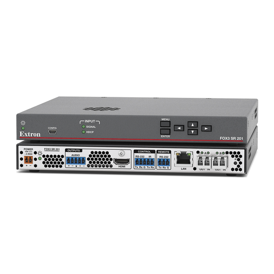
Figure 1.
FOX3 SR 201 Rear Panel
Step 1 — Mounting
Turn off or disconnect all equipment power sources and mount the scaling receiver as required. For mounting details and
considerations, see the FOX3 SR 201 User Guide at www.extron.com.
Step 2 — Output Connections
a.
Connect an HDMI display to the HDMI output (see figure 1 ,
Tip
Sleeve
Tip
Sleeve
b.
Connect an audio output device to the Audio 5-pole captive screw port (
Unbalanced Stereo Input
connector).
No Ground Here
Tip
Sleeves
Tip
No Ground Here
Unbalanced Stereo Output
Figure 2.
Audio Wiring Diagrams
ATTENTION:
•
For unbalanced audio, connect the sleeves to the ground contact. DO NOT connect the sleeves to the negative (–)
contacts.
•
Pour l'audio asymétrique, connectez les manchons au contact au sol. Ne PAS connecter les manchons aux
contacts négatifs (–).
Step 3 — Control Connections
a.
To pass serial, IR data, or control signals, such as for serial control of a projector,
connect the master device to the transmitter and the controlled device to the
receiver via the CONTROL 5-pole captive screw connector (see
wiring).
NOTE:
For returned RS-232 and IR responses (from the scaling receiver to the
transmitter) install the receiver-Tx-to-transmitter-Rx fiber cable in
Le FOX3 SR 201 émet une lumière invisible en continu (conforme à la classe 1) qui peut être
CONTROL
REMOTE
RS-232
RS-232
IR
Tx Rx
G
Tx Rx
HDMI
Tx Rx G
D
D
D
E
E
E
F
F
F
Tip
Ring
Sleeves
Tip
Ring
Balanced Stereo Input
Tip
Ring
Sleeves
Tip
Ring
Balanced Stereo Output
Do not tin the wires!
www.extron.com
A
A
B
R
B
OUT IN
OUT IN
LAN
C
G
G
G
H
H
H
I
I
I
D
E
D
).
C
) (see figure 2 to wire the captive screw
E
and figure 3 for
step
4b.
(en anglais).
Power Inlet
F
Remote RS-232
G
Power LED
LAN Ethernet port
Audio output
H
SFP module and LEDs
I
HDMI output
Reset button
Control RS-232/IR port
IR Device
Rx
Tx
RS-232 Device
Figure 3.
RS-232 and IR Wiring
Tx
Gnd
Rx
Gnd
1
Advertisement
Table of Contents

Related Manuals for Extron electronics FOX3 SR 201


Summary of Contents for Extron electronics FOX3 SR 201
- Page 1 Produit laser de classe 1, voir le FOX3 SR 201 User Guide sur www.extron.com (en anglais). Installation Power Inlet Remote RS-232 POWER FOX3 SR 201 OUTPUTS CONTROL REMOTE 2.0 A MAX AUDIO RS-232 RS-232 Power LED...
- Page 2 MENU INPUT CONFIG SIGNAL HDCP FOX3 SR 201 ENTER Figure 5. FOX3 SR 201 Front Panel Power LED — Indicates power is applied to the unit. USB Config port — Connect a USB Mini-B cable to a computer to configure the device and update the firmware via Product Configuration Software (PCS), Simple Instruction Set (SIS) commands, or internal web pages.
- Page 3 Menu and Enter buttons — Press these buttons to access and navigate the on-screen display menu system. Navigation buttons — Press these buttons to navigate through the on-screen display menu system or change settings. Reset Press the rear panel recessed reset button (see figure 1, on page 1) if the FOX3 scaling receiver firmware is corrupted or the unit gets disconnected during the update process.
- Page 4 The FOX3 scaling receiver can be configured via the Product Configuration Software when it is installed on a connected host device, such as a PC, through the front panel USB port or LAN port (see the FOX3 SR 201 User Guide for more details).
- Page 5 The following table is a partial list of SIS commands and output resolutions. For a complete listing of SIS commands,output resolutions, and instructions to install an SSH client, see the FOX3 SR 201 User Guide. Command and Response Table for SIS Commands...
- Page 6 , 50- 1.3A Ethernet -2 32 -2 32 D IO W ER 0. 7 Extron RS-232 Audio FOX3 SR 201 Output HDMI Fiber Optic Receiver Output M OD Extron SI 28 Surface-mount 4K Display Speakers For information on safety guidelines, regulatory compliances, EMI/EMF compatibility, accessibility, and related topics, see the Extron Safety and Regulatory Compliance Guide on the Extron website.
Need help?
Do you have a question about the FOX3 SR 201 and is the answer not in the manual?
Questions and answers