Table of Contents
Advertisement
Quick Links
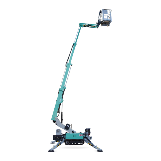
IM R13 T
MOBILE ELEVATING WORK PLATFORM
USE AND MAINTENANCE MANUAL
MUM IM R13 T USA R00 07/2019
TRANSLATION OF THE ORIGINAL INSTRUCTIONS
IMER International S.p.A.
Access Platform Division
Via San Francesco d'Assisi, 8 - 46020 Pegognaga (Mantova) - ITALY
Tel. +39 0376 554011 - Fax +39 0376 559855
www.imergroup.com
Advertisement
Table of Contents

Related Manuals for IMER IM R13 T


Summary of Contents for IMER IM R13 T
- Page 1 IM R13 T MOBILE ELEVATING WORK PLATFORM USE AND MAINTENANCE MANUAL MUM IM R13 T USA R00 07/2019 TRANSLATION OF THE ORIGINAL INSTRUCTIONS IMER International S.p.A. Access Platform Division Via San Francesco d’Assisi, 8 - 46020 Pegognaga (Mantova) - ITALY Tel.
- Page 2 Via Salceto, 53-55 - 53036 POGGIBONSI (SI) (ITALY) Tel. +39 0577 97341 - Fax +39 0577 983304 Access Platform Division 46020 PEGOGNAGA (MN) ITALIA Via S. Francesco D’Assisi, 8 Tel. +39 0376 554011 Fax +39 0376 559855 IM R13 T è conforme allo standard ANSI A92.20/2018...
-
Page 3: Table Of Contents
USE AND MAINTENANCE MANUAL IM R13 T Table of contents Presentation ....................... 8 Static and dynamic tests .................. 9 After-sale service....................9 Spare-parts service ................... 9 Liability ....................... 9 CE conformity declaration IM R13 B.............. 10 General instructions - safety ................11 Manual ....................... - Page 4 USE AND MAINTENANCE MANUAL IM R13 T Overall dimensions ..................32 Work diagram ..................... 34 Plates and labels ..................35 Identification ....................36 Standard equipment ................... 37 Optional ...................... 37 Machine operations ..................38 Ground movements - Aerial movements ............ 38 Ground movements ................
- Page 5 USE AND MAINTENANCE MANUAL IM R13 T Electric valves for emergency operations ..........51 Manual pump .................... 52 Electric pump 12 V (optional) ..............52 Control stations ....................53 Control panels .................... 54 Ground control panel ................54 Lifting/lowering of the jib ................56 Extension/retraction of the telescopic boom ..........
- Page 6 USE AND MAINTENANCE MANUAL IM R13 T Procedure with the machine blocked without alert signals (optional) ... 95 From the ground ..................95 From the platform control panel ..............95 Manual start-up of the diesel/petrol engine ..........96 Battery recharging................... 98 Battery charges characteristics;...
- Page 7 USE AND MAINTENANCE MANUAL IM R13 T Checking the hydraulic tubes ..............116 Check the performance ................116 Safety speed ..................116 Lifting/lowering of the boom .............. 116 Extension/retraction of the telescopic boom ........117 Turret rotation ................... 117 Lifting/lowering of the jib ..............117 Check the power and auxiliary cables ............
- Page 8 USE AND MAINTENANCE MANUAL IM R13 T This edition comprises the use and maintenance manual for a tracked, self-propelled, hydraulic scissor lift platform: IM R13 Designed and manufactured to be: • Powered with petrol; • Hydraulically operated and wit. proportional controls.
-
Page 9: Static And Dynamic Tests
Liability La IMER International S.p.A. shall be released from any liability or any obligations for any damage to persons or objects caused by any of the reasons listed further below: •... -
Page 10: General Instructions - Safety
USE AND MAINTENANCE MANUAL IM R13 T General instructions - safety Manual A suitable working safety is very important in order to avoid serious injuries for the operator himself and for the other persons, therefore it is compulsory to carefully read and well-understand this manual to know the exact and essential instructions for the use of the machine and the maintenance operations. -
Page 11: Operator's Requirements
USE AND MAINTENANCE MANUAL IM R13 T Operator’s requirements Only qualified and skilled operators can use these machines The operator shall: 1. Read and well understand all the documentation provided with the machine, be properly trained and instructed in the correct use of the machine and know the safety rules and devices. - Page 12 USE AND MAINTENANCE MANUAL IM R13 T In particular • Be aware that the tracked platforms with remote control can be used by qualified personnel only. • Do not give the platform control panel to people who have not been thoroughly trained.
-
Page 13: Distance From The Electric Lines
USE AND MAINTENANCE MANUAL IM R13 T Distance from the electric lines The machine is not electrically insulated and does not offer any protection against active parts, electrical lines and plants which are not protected or not sufficiently protected. Here below you can find a table concerning the safety distances to be compulsory observed according to the Italian law. -
Page 14: Unpermitted Operations
USE AND MAINTENANCE MANUAL IM R13 T Unpermitted operations It is strictly forbidden to use the machine: • On public roads. • Without an adequate environmental lighting to work or to move under safety conditions. • Work in case of strong storm, with or without rain, or with wind with speed higher than 12.5 m/s, 6th grade of the Beaufort scale described below. - Page 15 USE AND MAINTENANCE MANUAL IM R13 T Beaufort Wind Scale Wind Wind Wind speed speed Sea conditions Land conditions description (km/h) (m/s) 0 Calm Flat Calm. Smoke rises vertically. Wind motion visible in 1 Light air 0.3-1.5 Ripples without crests. White foamy crests are not yet formed.
-
Page 16: To Minimize Risks
USE AND MAINTENANCE MANUAL IM R13 T To minimize risks Follow the instructions below: Risk of overturning • Check the ground is firm and even. • Do not use the machine on slippery, icy, muddy ground and with holes, which has a slope higher than the allowed limit. -
Page 17: Risk Of Falling
USE AND MAINTENANCE MANUAL IM R13 T Risk of falling • The use of safety belts is compulsory. • Do not lean out of the safety perimetric guard rails of the platform. • Do not use guard rails as admittance means to get on or get down from the platform. -
Page 18: Residual Risks
USE AND MAINTENANCE MANUAL IM R13 T Residual risks The plates and labels listed below indicate the residual risks that remain despite there being protective measures incorporated into the machine’s design and regardless of the safety devices adopted. -
Page 19: Description Of The Machine
USE AND MAINTENANCE MANUAL IM R13 T Description of the machine... - Page 20 USE AND MAINTENANCE MANUAL IM R13 T The tracked aerial platform IM R13 is used to lift persons, materials and equipment to enable works to be performed at certain heights (indoor and outdoor). It is intended to be used accordingly with the foreseen technical data described in the suitable sheet, on solid and strong grounds and not before a Qualified Operator has checked the operational safety.
-
Page 21: Main Components
USE AND MAINTENANCE MANUAL IM R13 T Main components 1. Platform control panel 2. Platform - cage 3. Jib 4. Telescopic booms 5. Turret 6. Left box 7. Right box 8. Ground control panel 9. Driving wheels 10. Stabilizers LEFT SIDE... -
Page 22: Control And Power Instruments
USE AND MAINTENANCE MANUAL IM R13 T Control and power instruments RIGHT SIDE PETROL ENGINE INCLINOMETER (optional) BATTERY MANUAL PUMP HYDRAULIC GROUPS LEFT SIDE SPIRIT LEVEL RECEIVER ELECTRIC MOTOR PUMP 12 V (optional) GROUND CONTROL PANEL SOCKET 230 V... - Page 23 USE AND MAINTENANCE MANUAL IM R13 T CAGE PLATFORM CONTROL PANEL The platform control panel is extractable and may be used by the operator also from the ground.
-
Page 24: Electronic Circuit
USE AND MAINTENANCE MANUAL IM R13 T Electronic circuit The electronic equipment consists of electronic microprocessor devices for the machine operation: • Two main control units located behind the ground control panel. • Receiver (communicating via the CAN Bus transmission protocol with the two main boards) •... -
Page 25: Radio Control And Remote Control
USE AND MAINTENANCE MANUAL IM R13 T Radio control and remote control Radio control (optional) The radio control is a digital remote control system, based on microprocessor technology, protected against electromagnetic and radio interference. The radio control consists of: a PORTABLE CONTROL UNIT (Platform PANEL) with joystick controls •... -
Page 26: Remote Control
USE AND MAINTENANCE MANUAL IM R13 T Remote control The remote control is a wire control system with the same functionality as the radio system, but without the remote control. The remote control consists of: • a PORTABLE CONTROL UNIT (Platform PANEL) with joystick controls for proportional control of movements (switches and buttons for ON/ OFF functions, warning lights, graphic LCD). -
Page 27: Receiver
USE AND MAINTENANCE MANUAL IM R13 T Dead Man Button Dead Man Button is located on the right side of the platform panel,on the basket It is an additionaly securety for operator, because it allows movements only if it is pressed... -
Page 28: Platform Panel Battery For Radio Control
USE AND MAINTENANCE MANUAL IM R13 T Platform panel battery for radio control The battery inserted into the lower part of the platform panel, allows for the use by radio. Another battery is supplied to be always placed in the battery charger. -
Page 29: Charging The Battery
USE AND MAINTENANCE MANUAL IM R13 T Charging the battery The battery charger starts a charge cycle when a battery is inserted (the green LED starts blinking). The battery charging of the radio control takes place in two consecutive steps: •... -
Page 30: Technical Data
USE AND MAINTENANCE MANUAL IM R13 T Technical data Unit of Description IM R13 T measurement Max. working load (including 2 person) 510 - 230 lbs - kg Drive speed 0.8 - 1.3 mph - km/h Max. slope Max. allowed side force... -
Page 31: Overall Dimensions
USE AND MAINTENANCE MANUAL IM R13 T Overall dimensions... - Page 32 USE AND MAINTENANCE MANUAL IM R13 T...
-
Page 33: Work Diagram
USE AND MAINTENANCE MANUAL IM R13 T Work diagram... -
Page 34: Plates And Labels
USE AND MAINTENANCE MANUAL IM R13 T Plates and labels Using the illustrations, check that all the plates and labels are in place. Plates and labels that contain no text will have an 8-digit numbering or an alphanumeric code ending with XX. -
Page 35: Identification
USE AND MAINTENANCE MANUAL IM R13 T Identification Two metal plates fixed to the chassis and the cage specify all data necessary to identify the model of the machine. IM R13 T 8,2 + 2,2 12/110 C20 The data refers to the standard model. -
Page 36: Standard Equipment
USE AND MAINTENANCE MANUAL IM R13 T Standard equipment • Proportional and simultaneous movements • Remote control for wire control • Parking brakes • Rubber crawling tracks • Electric pump 230 V - 16 A for internal use • 360° turret rotation (180° + 180°) •... -
Page 37: Ground Movements - Aerial Movements
USE AND MAINTENANCE MANUAL IM R13 T Ground movements - Aerial movements The operations refer to the two parts of the machine: the lower (ground) part and the aerial part that extends upward into the air. The lower (ground) part of the machine is made up of the carriage (with crawling tracks and stabilisers). -
Page 38: Ground Movements
USE AND MAINTENANCE MANUAL IM R13 T Ground movements Drive and Steering For driving purposes the chassis is equipped with two hydraulic motors which drive the rubber crawling tracks. The steering is facilitated by driving the tracks at different speeds. -
Page 39: Aerial Movements
USE AND MAINTENANCE MANUAL IM R13 T Aerial movements Lifting/lowering of the boom A hydraulic cylinder located between turret and the lifting boom facilitates this operation. Turret rotation The operation is facilitated by a hydraulic motor, which moves a turntable on the chassis. The turret rotates 360°... -
Page 40: Machine Status
USE AND MAINTENANCE MANUAL IM R13 T Machine status Various terms indicating the status or position of the machine are often referenced throughout this Manual. Every status of the machine is shown on the display unit of the platform control panel. -
Page 41: Machine In The Safety Transport Mode
USE AND MAINTENANCE MANUAL IM R13 T Machine in the safety transport mode The machine is in SAFETY TRANSPORT mode when the lifting boom is lifted no more than 5° and no stabiliser is pressurised. 5° The safety transport mode facilitates: •... -
Page 42: Stabilised And Stowed Away Machine
USE AND MAINTENANCE MANUAL IM R13 T Stabilised and stowed away machine The machine is STABILISED AND STOWED AWAY when all 4 stabilisers are under pressure and the cage is in a stowed away position. The STABILISED AND STOWED AWAY MODE facilitates: •... -
Page 43: Open Machine
USE AND MAINTENANCE MANUAL IM R13 T Open machine The machine is OPEN when it is stabilised and the boom lifted over 5° angle. When the MACHINE is STABILISED AND STOWED AWAY: • By lifting the BOOM ABOVE 5° all the movements of the aerial part are activated. -
Page 44: Safety Systems
USE AND MAINTENANCE MANUAL IM R13 T Safety systems The machine is provided with several safety devices safeguarding its normal operation in order to preclude any accidental injuries (accidents). Adequate command of the characteristics of the safety devices on the machine is crucial. The machine is not to be put into operation unless the following sections of the manual have been read carefully and understood. -
Page 45: Operating Irregularities
USE AND MAINTENANCE MANUAL IM R13 T Operating irregularities In the case of any malfunction detected by the self-diagnostics of the main control units, the display unit on the platform control panel will show an error code. Safety belt attachment points The machine is fitted with suitable anchorage points for the safety belts. - Page 46 USE AND MAINTENANCE MANUAL IM R13 T...
-
Page 47: Moment Limiter
USE AND MAINTENANCE MANUAL IM R13 T Moment limiter The overturning moment limiter consists of a strain pivot placed on the pin at the boom of the lift cylinder and checks whether the overturning moment has exceeded its maximum value... -
Page 48: Spirit Level
USE AND MAINTENANCE MANUAL IM R13 T Spirit level The spirit level is placed in the in the rear part part of the chassis, visible both from the cage and from the ground. During the levelling out procedures, make sure to use the spirit level to check if the permissible level of inclination of 1°... -
Page 49: Microswitches
USE AND MAINTENANCE MANUAL IM R13 T Microswitches Microswitches SQ1A-B The SQ1A and SQ1B micro switches are located in the stowing seat of the cage indicating its presence there, therefore representing the condition of the machine stowed away. Microswitch SQ8 (lifting boom) The SQ8 micro switch is located on the turret and checks the angulation of the lifting boom. - Page 50 USE AND MAINTENANCE MANUAL IM R13 T...
-
Page 51: Emergency Devices
USE AND MAINTENANCE MANUAL IM R13 T Emergency devices Emergency devices are fitted onto the machine. It is fundamental to know the characteristics and the functioning of all the emergency devices; it is recommended not to operate the machine before reading and understanding well the following section. -
Page 52: Manual Pump
USE AND MAINTENANCE MANUAL IM R13 T Manual pump The manual pump is located on the right-hand side of the oil tank, while its operating lever is located at the base of the turret. The manual pump is used to supply oil under pressure in any emergency situations. -
Page 53: Control Stations
USE AND MAINTENANCE MANUAL IM R13 T Control stations The operators control stations are: • Platform control station located on the ground • Platform control station located on the cage support • Ground control station located on the frame base When one of the control station is operated, the other one is disabled. -
Page 54: Ground Control Panel
USE AND MAINTENANCE MANUAL IM R13 T Ground control panel Warning light machine ON (green) Cage balancing Warning light red (A) Turret rotation Warning light green (B) Lifting/lowering of Red emergency stop Dead-man button the jib button Emergency Extension/retraction of... - Page 55 USE AND MAINTENANCE MANUAL IM R13 T Selector key (3 positions) • Central position: the machine is powered off • Right-hand position: controls in the platform control panel are active • Left-hand position: controls in the ground control panel are active Red emergency stop button •...
-
Page 56: Lifting/Lowering Of The Jib
USE AND MAINTENANCE MANUAL IM R13 T Lifting/lowering of the jib • Upwards to lift the jib • Downwards to lower the jib Extension/retraction of the telescopic boom • To the right to extend the telescopic boom • To the left to retract the telescopic boom Lifting/lowering of the lifting boom •... - Page 57 USE AND MAINTENANCE MANUAL IM R13 T Machine ON warning light The green ON warning light lights up when the selector key 1 is not in its central position. Disconnected mains warning light If the red warning light lights up, the mains is disconnected. When the diesel/ petrol engine is started, the warning light goes out.
-
Page 58: Platform Control Panel
USE AND MAINTENANCE MANUAL IM R13 T Platform control panel Switch the platform control panel on with the switch and wait until red LED ON is on . Display unit Joystick controls Switch 15 S selectors STOP OPTION OPTION OPTION... -
Page 59: Selector Keys
USE AND MAINTENANCE MANUAL IM R13 T Selector keys Aerial controls Ground controls Automatic stabilisation (optional) 15 S STOP OPTION OPTION OPTION Crawling tracks movement (optional) Drive speed Motor speed Cage balancing Crawling tracks movement (OPTIONAL) • forward - it widens the span of the crawling tracks •... - Page 60 USE AND MAINTENANCE MANUAL IM R13 T Driving speed • to the right - maximum speed • to the left - average speed • at the centre - minimum speed Using the diesel/petrol engine The speed can only be selected when the machine is stowed away and in the safety transport mode.
-
Page 61: Switches
USE AND MAINTENANCE MANUAL IM R13 T Switches Emergency stop button 15 S STOP OPTION OPTION OPTION Emergency pump start-up (optional) Motor start-up aid ON/OFF platform control panel Motor start-up Motor shut-down Platform control panel switching on The I1 switch must be used to switch the platform control panel on. - Page 62 USE AND MAINTENANCE MANUAL IM R13 T 15 S Engine start-up aid OPTION Helps to start-up the engine in cold weather. • Press down simultaneously with the I2 key to activate the air supply into the engine Engine shutdown STOP It shuts down the electric motor or a diesel/petrol engine.
-
Page 63: Joystick Controls
USE AND MAINTENANCE MANUAL IM R13 T Joystick controls Table of operations controlled by the joystick controls, depending on the actual position of the S6 selector key. S6 forward Aerial part operations M1 - NOT USED Forward Lifting M2 - BOOM... -
Page 64: Led Bar
USE AND MAINTENANCE MANUAL IM R13 T LED bar Disconnection from the mains voltage Connection to the mains voltage Connection to the mains voltage Green warning light; when it lights up the machine is connected to the mains. Disconnection from the mains voltage Orange warning light;... -
Page 65: Display Unit
USE AND MAINTENANCE MANUAL IM R13 T Display unit The display unit shows: • Engine status • Machine status • Alerts Engine status The engine status is visualised by 4 pictograms : Diesel/petrol engine on Oil in the engines •... -
Page 66: Machine Status
USE AND MAINTENANCE MANUAL IM R13 T Machine status STOWED AWAY MACHINE The machine is stowed away when the cage is in its stowed away seat and none of the stabilisers are under pressure. When the machine is stowed away the following actions may be executed: •... - Page 67 USE AND MAINTENANCE MANUAL IM R13 T STABILISED AND STOWED AWAY MACHINE The machine is STABILISED AND STOWED AWAY when all 4 stabilisers are under pressure and the cage is in its stowed away seat. With the machine in the stabilised and stowed away mode the following operations may be performed: •...
- Page 68 USE AND MAINTENANCE MANUAL IM R13 T By lifting the boom and taking the cage out of its stowed away seat, the pictogram of moment control will appear on the display unit. By taking in consideration other pictograms more information on the machine status may thus be obtained.
- Page 69 USE AND MAINTENANCE MANUAL IM R13 T The following pictograms may be displayed if the automatic stabilisation option is present: The machine is STABILISED, LEVELLED OUT and NO LONGER STOWED AWAY. The stabilisers movement is blocked. By lifting the boom above 5°, all the movements of the aerial part are activated.
-
Page 70: Use Of The Machine
USE AND MAINTENANCE MANUAL IM R13 T Use of the machine... -
Page 71: Checking Before Using
USE AND MAINTENANCE MANUAL IM R13 T Before carrying out any operations, it is necessary to read and well understand the contents of this manual, as well as all the instructions on the plates and labels Checking before using Before the machine is put into operation and any operation is executed, it must be thoroughly checked visually in the way described further below. -
Page 72: Operation Of The Machine
USE AND MAINTENANCE MANUAL IM R13 T Operation of the machine... - Page 73 USE AND MAINTENANCE MANUAL IM R13 T In order to lift up persons, materials and/or equipment to facilitate the works at some height, it is necessary to do the following: 1. Put the machine into the working position using the drive and the steering;...
-
Page 74: Setting The Machine Into The Working Position
USE AND MAINTENANCE MANUAL IM R13 T Setting the machine into the working position To place the machine in the working position: • Turn on the machine • Start the engine • Perform a movement Starting the machine up 15 S... -
Page 75: Start The Engine
USE AND MAINTENANCE MANUAL IM R13 T Start the engine Start up the diesel/petrol engine or electric motor by pressing down the I2 selector key. 15 S STOP OPTION OPTION OPTION When the yellow warning light is lit up, the machine is disconnected from the mains and the diesel/petrol engine will start up. -
Page 76: Drive And Steering
USE AND MAINTENANCE MANUAL IM R13 T Drive and Steering To make use of the machine’s drive, the machine must be stowed away, or in the safety transport mode When controlling the drive from the ground using the platform control panel, maintain a... -
Page 77: Driving On An Inclined Terrain
USE AND MAINTENANCE MANUAL IM R13 T Driving on an inclined terrain • Never attempt to drive the machine along the terrain of an inclination exceeding 15° (27%). • When driving the machine across any laterally sloping terrain, widen the span of the crawling tracks to the maximum width (if provided by the machine configuration) to increase the machine’s... -
Page 78: Machine Stabilisation
USE AND MAINTENANCE MANUAL IM R13 T Machine stabilisation Once the machine is properly positioned, the procedures of stabilisation and levelling out may be commenced. Stabilisers may be repositioned only when the machine is stowed away Before commencing any machine stabilisation operations, make sure there are no persons... -
Page 79: Manual Stabilisation
USE AND MAINTENANCE MANUAL IM R13 T Manual stabilisation Using the 4 joysticks: M2 – M3 – M4 – M5 push them backward to have the machine effectively stabilised. This pictogram will appear on the OPTION platform control panel A single stabiliser foot that touches the ground may not be lowered until... -
Page 80: Automatic Stabilisation (Optional)
USE AND MAINTENANCE MANUAL IM R13 T Automatic stabilisation (optional) Turn S5 backward and keep it pressed for the duration of the operation; the stabilisers are lowered down and the machine is now stabilised and levelled out. M2 M3 M4 M5... - Page 81 USE AND MAINTENANCE MANUAL IM R13 T...
-
Page 82: Moving The Aerial Part
USE AND MAINTENANCE MANUAL IM R13 T After the completion of the positioning and the stabilisation phases have the platform control panel inserted back into its docking station in the cage. If there is the radio control unit make sure that micro-magnetic switch placed on the side of the platform control panel is securely pushed into its socket. - Page 83 USE AND MAINTENANCE MANUAL IM R13 T M2 M3 M4 M5 JOYSTICK AERIAL MOVEMENT M1 Not used Forward Lifting M2 Boom Backward Lowering Forward Extension M3 Boom retraction Backward Retraction Forward Lifting M4 Jib Backward Lowering M5 Not used Forward...
-
Page 84: Returning To The Stowed Away Mode
USE AND MAINTENANCE MANUAL IM R13 T Returning to the stowed away mode After completing the works at height return to the stowed away mode. Retraction of the aerial part Retract completely the extension by pulling the M3 joystick backward... -
Page 85: Retraction Of The Stabilisers
USE AND MAINTENANCE MANUAL IM R13 T Retraction of the stabilisers The retraction of the stabilisers is possible only with the cage in its stowed away seat. Push S6 backwards to activate the ground movements. Manual procedure Using the 4 joystick controls M2 – M3 – M4 – M5 push them forward to lift the feet. -
Page 86: Switching Off The Engine
USE AND MAINTENANCE MANUAL IM R13 T Switching off the engine From the platform control panel • Switch the diesel/petrol engine or electric motor off using the I4 switch STOP From the ground control panel • Press the emergency button 2... -
Page 87: Switching The Machine Off
USE AND MAINTENANCE MANUAL IM R13 T Switching the machine off 15 S STOP OPTION OPTION OPTION Switch off the platform control panel with the I1 button Turn the key into the central position in the ground control panel End of work •... -
Page 88: Emergency Procedures
USE AND MAINTENANCE MANUAL IM R13 T Emergency procedures... -
Page 89: Emergency Manual Procedures
USE AND MAINTENANCE MANUAL IM R13 T Emergency manual procedures If the machine is blocked due to mechanical or electrical fault, or due to the operator’s fault, it is possible to put it into the transport configuration which can be facilitated by the operator from the ground. - Page 90 USE AND MAINTENANCE MANUAL IM R13 T...
-
Page 91: Standard Emergency Procedure
USE AND MAINTENANCE MANUAL IM R13 T Standard emergency procedure Emergency electric valves The electric valves to use for the emergency movements are positioned on the hydraulic blocks (A - B - C - D - E): • A and B in the left box •... - Page 92 USE AND MAINTENANCE MANUAL IM R13 T To perform a movement: 1. Identify on main block A the electric valve associated with the operation. 2. Unscrew the protective nut on the electric valve (using adjustable wrench No. 13). 3. Screw the electric valve pawl to the end without forcing 4.
-
Page 93: Example 1
USE AND MAINTENANCE MANUAL IM R13 T EXAMPLE 1 If necessary, carry out the boom lowering operation: 1. This operation is associated with the electric valve YV1B of the main block A. 2. Unscrew the protective nut on the electric valve YV1B (using adjustable wrench No. 13). -
Page 94: Example 2
USE AND MAINTENANCE MANUAL IM R13 T EXAMPLE 2 If necessary, carry out the lowering of the rear left stabiliser operation: The operation is associated with the electric valves: • YV2A of main block A. • YV12 of block B. - Page 95 USE AND MAINTENANCE MANUAL IM R13 T On this page and in the following 2 tables there is a summary of the electric valves and the operations controlled by them. YV1A YV1B YV2A YV2B YV10 YV11 YV12...
- Page 96 USE AND MAINTENANCE MANUAL IM R13 T YV1A YV1B YV2A YV2B YV10 YV11 YV12...
-
Page 97: Procedure With The Machine Blocked Without Alert Signals (Optional)
USE AND MAINTENANCE MANUAL IM R13 T Procedure with the machine blocked without alert signals (optional) Make sure that the machine is not connected to the 220 V network or that the differential magneto-thermal switch is deactivated In the radio-controlled models, the platform control panel must be switched on From the ground Execute the following operations from the ground control panel. -
Page 98: Manual Start-Up Of The Diesel/Petrol Engine
USE AND MAINTENANCE MANUAL IM R13 T Manual start-up of the diesel/petrol engine 1. Find the 4 wires, as shown in the figure, on the right-hand side of the engine, (2 yellow ones, 1 red and 1 black) 2. Remove the red and black wires from the respective connectors 3. - Page 99 USE AND MAINTENANCE MANUAL IM R13 T 4. Pull the engine start-up lever until resistance is felt and then release it 5. Pull the air lever to the outside 6. Pull the lever decisively...
-
Page 100: Battery Recharging
USE AND MAINTENANCE MANUAL IM R13 T Battery recharging The following pictogram on the display unit on the platform control panel will appear, in addition to indicating the fault of the alternator (lit up steadily); it indicates the status of the starter battery: •... -
Page 101: Transport
USE AND MAINTENANCE MANUAL IM R13 T Transport Make sure the vehicle used for the transport and/or lifting of the machine can support its weight Loading and unloading of the machine Loading and unloading of the machine onto the platform of the carrying vehicle may be done as follows: •... -
Page 102: By Having It Lifted Directly
USE AND MAINTENANCE MANUAL IM R13 T By having it lifted directly The lifting may be carried out with a crane or a bridge crane. Use the tape, chains and hooks in perfect operating condition only. • The machine may be lifted up in a stowed away mode only. -
Page 103: How To Uncouple The Cage
USE AND MAINTENANCE MANUAL IM R13 T How to uncouple the cage • Park the carrying vehicle on a flat surface • Keep on lowering the cage, using the balancing control, until it touches the ground • Remove the flexible plug out of the pin... -
Page 104: Fastening The Machine
USE AND MAINTENANCE MANUAL IM R13 T Fastening the machine Prior to shipment make sure the machine is properly secured on the carrying vehicle platform with tapes threaded through the 4 attachment points (2 front and 2 rear), as indicated on the appropriate labels. -
Page 105: Storage
USE AND MAINTENANCE MANUAL IM R13 T Storage In the event of long storage periods, shelter the machine in a dry and ventilated place, with the battery fully charged. If possible, keep the battery charger connected and powered to keep the battery charged, otherwise recharge the battery on regular basis, every 2 months. -
Page 106: Maintenance
USE AND MAINTENANCE MANUAL IM R13 T Maintenance Long life and maximum safety during machine operation can only be assured by careful and regular maintenance. The schedule indicated in the maintenance summary table refers to normal use conditions, whereas in the case of any heavy duty working conditions (extreme temperature, polluted atmosphere, high humidity, high elevation, etc.) those intervals must be shorter. -
Page 107: Maintenance Summary Table
USE AND MAINTENANCE MANUAL IM R13 T Maintenance summary table It is recommended to have an annual inspection carried out by an authorised service centre OPERATIONS TO BE CARRIED OUT Check plates and labels Check the oil level Change the oil filter cartridge... -
Page 108: Maintenance Of The Diesel/Petrol Engine
USE AND MAINTENANCE MANUAL IM R13 T Maintenance of the diesel/petrol engine The petrol/diesel engine maintenance table is provided below. For more detailed instructions consult the Manual enclosed with the machine documentation. OPERATIONS TO BE CARRIED OUT Check the oil level in the engine... -
Page 109: Maintenance Of The Electric Motor
USE AND MAINTENANCE MANUAL IM R13 T Maintenance of the electric motor Periodically check: • engine functions for any vibrations or irregular noise • air inlet on the rotor cover for any obstructions • for dust, oil leakage or other undue grime on the motor... -
Page 110: Oil Level Check
During checks, verify that oil keeps its clarity, colour and viscosity characteristics; replace, if necessary. IMER suggests anyway to replace the oil completely every 3 years. The complete oil change must be carried out with the machine stowed away The tap placed under the tank facilitates a total oil drainage. -
Page 111: Change The Oil Filter Cartridge
USE AND MAINTENANCE MANUAL IM R13 T Change the oil filter cartridge The cartridge must be replaced when: • upon every oil replacement • in compliance with the schedule stipulated in the Table of Maintenance • when the error code 556 is displayed on the platform control panel display and all the machine... -
Page 112: Battery
USE AND MAINTENANCE MANUAL IM R13 T Battery The AGM battery does not require the electrolyte level to be checked. Clean the terminal contact surfaces and then lubricate with antiacid grease or Vaseline. Charge the battery The battery charge level can be read out on the pushbutton panel. -
Page 113: Check The Tightening Of All The Screws
USE AND MAINTENANCE MANUAL IM R13 T Check the tightening of all the screws Tightening torque DESCRIPTION TYPE M16X70 UNI5931 Screws fastening the thrust block to the chassis M16X70 UNI5739 Screws fastening the thrust block to M16X70 UNI5931 the turret... -
Page 114: Check The Safety Devices
USE AND MAINTENANCE MANUAL IM R13 T Check the safety devices The following test facilitates checking that all the safety devices on the machine are fully operational. The safety systems installed on the machine are inevitably subject to wear and loss of calibration, therefore they must be periodically checked and maintained in perfect service condition. - Page 115 USE AND MAINTENANCE MANUAL IM R13 T...
-
Page 116: Microswitches
USE AND MAINTENANCE MANUAL IM R13 T Microswitches SQ1A-B SQ1A and SQ1B micro switches are located in the stowing seat of the cage indicating their presence there. Set the machine into the stowed away position, and check if the following pictogram is displayed on the platform control panel: SQ8 checks the angulation of the boom. -
Page 117: Check Emergency Manual Operations
USE AND MAINTENANCE MANUAL IM R13 T Check emergency manual operations See paragraph “Manual emergency operations”. Checking the brakes Good grip Parking brakes must be capable of stopping the machine on a maximum slope, as indicated in the “Technical Data” Table. -
Page 118: Carry Out Structural Check
USE AND MAINTENANCE MANUAL IM R13 T Carry out structural check General • Check that mechanical structures are protected against oxidation and, if necessary, retouch the oxidised areas. Chassis • Check the most important welds visually or by means of penetrating fluids:... -
Page 119: Checking The Hydraulic Tubes
USE AND MAINTENANCE MANUAL IM R13 T Checking the hydraulic tubes Hydraulic oil is a pollutant Avoid spilling the hydraulic fluid by using collection tanks, and take precautions against the accidental loss and escape of hydraulic fluid by using oil-absorbent products •... -
Page 120: Extension/Retraction Of The Telescopic Boom
USE AND MAINTENANCE MANUAL IM R13 T Extension/retraction of the telescopic boom • Select the extension of the telescopic boom from the ground control panel and check that is takes about 30 sec. for a complete extension. • Retract the boom and check that it takes about 30 sec. -
Page 121: Maintenance Of Rubber Crawling Tracks
USE AND MAINTENANCE MANUAL IM R13 T Maintenance of rubber crawling tracks Checking the tension of the crawling tracks • Position the machine on a compact and flat surface • Have the machine stabilised • Measure the distance A between the outer and inner part of the rubber track in relation to 2 central rolls The tension is normal if the distance is between 10 and 15 mm. -
Page 122: How To Loosen Up Or Stretch The Crawling Track
USE AND MAINTENANCE MANUAL IM R13 T How to loosen up or stretch the crawling track Perform the operations with the machine stabilised. The grease contained in the hydraulic crawling track is pressurised. Do not loosen the valve by more than one turn; if the valve is loosened too much, it may be blown off due to the pressure of the grease. -
Page 123: How To Replace The Crawling Tracks
USE AND MAINTENANCE MANUAL IM R13 T How to replace the crawling tracks Perform the operations with the machine stabilised. The grease contained in the hydraulic crawling track is pressurised. Do not loosen the valve by more than one turn; if the valve is loosened too much, it may be blown off due to the pressure of the grease. - Page 124 USE AND MAINTENANCE MANUAL IM R13 T This page is left out empty intentionally...
-
Page 125: Machine Logbook
USE AND MAINTENANCE MANUAL IM R13 T Machine Logbook Reference to legislation This Machine Logbook is issued to the aerial platform users, in compliance with the provisions of the Enclosure No. I of the 2006/42/EC Directive. Instructions for keeping the Machine Logbook This Machine Logbook must be considered as an integral part of the aerial platform and must be stored on the platform for the duration of its service life, until it is finally dismantled.