
Related Manuals for Dataman DATAMAN-848PRO2


Summary of Contents for Dataman DATAMAN-848PRO2
- Page 1 User's Manual for DATAMAN-848PRO2 Fast universal 8x 48-pindriver Stand-Alone concurrent multiprogramming system November 2009...
- Page 2 This document is copyrighted by Dataman Programmers Ltd, United Kingdom. All rights reserved. This document or any part of it may not be copied, reproduced or translated in any form or in any way without the prior written permission of Dataman Programmers Ltd.
-
Page 3: Table Of Contents
Table of contents Introduction ..........................4 DATAMAN-848PRO2 elements..................... 6 Manipulation of the programmed device................7 In-system serial programming using DATAMAN-848PRO2 ..........7 Selftest and calibration check ....................10 Technical specification......................11 Programming a device......................16 Engineering mode........................ 16 Production mode........................20 Software .......................... -
Page 4: Introduction
The operator merely removes the finished chip and inserts a new chip. Operator training is therefore minimized. DATAMAN-848PRO2 supports all kinds and types of silicon technology found in todays and tomorrows programmable devices, without requiring family specific modules. You... - Page 5 These capabilities supported by overcurrent protection and signature-byte check help prevent chip damage due to operator error. DATAMAN-848PRO2 has a selftest capability which allows the diagnostic part of the software to thoroughly check the health of each programming module.
-
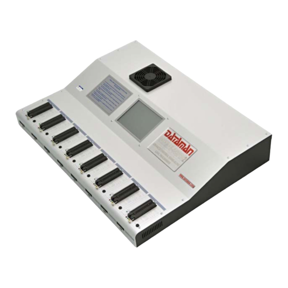
Page 6: Dataman-848Pro2 Elements
The advanced design of the DATAMAN-848PRO2 Stand-Alone multiprogramming system, including protective circuits, original brand components and careful manufacturing with long burning-in periods allows us to provide a three-year warranty on parts and labor for the programmer (limited 25 000-cycle warranty on ZIF sockets). -
Page 7: Manipulation Of The Programmed Device
(turning off the programmer), but the contents of programmed cells may remain undefined. Don't remove the target device from the ZIF socket during operations with device (BUSY LED on). In-system serial programming DATAMAN- 848PRO2 Optimized advanced pindrivers deliver high programming performance without overshoot or ground bounce for all device technologies. - Page 8 For general information, recommendations and directions about the ISP interface, see the manual section: Common notes / ISP . Description of ISP connector Front view at ISP connector. H/L/read driver pins 3, 5, 7, 9, 11, 13 of ISP connector pin 14 of ISP connector pin of ISP drivers in programmer...
- Page 9 • Use only the ISP cable provided. When you use other ISP cables (other material, length…), programming may become unreliable. • DATAMAN-848PRO2 can supply power to the programmed device (pin 1 of ISP connector) and the target system (pin 19 and 20 of ISP connector) with some limitations.
-
Page 10: Selftest And Calibration Check
Selftest and calibration check can be run in engineering mode only. This mode is available only when external display, keyboard and mouse are connected to DATAMAN-848PRO2. If you feel that your programmer does not react according to your expectations, please run the programmer (ISP connector’s) selftest using the Diagnostic POD (Diagnostic... -
Page 11: Technical Specification
Technical specification Specification (DATAMAN-848PRO2 multiprogramming system) • 8x universal programming modules (8x 48-pin DIL ZIF sockets and 8x ISP connectors) • operation result LEDs, LED power • line power input 100-240VAC/60W max. • banana jack for ESD wrist strap connection •... - Page 12 • 1x VCCP voltage (range 2V..7V/100mA) , can be applied to two pins • programmed chip voltage (VCCP) with both source/sink capability and voltage sense • 1x VPP voltage (range 2V..25V/50mA) • target system supply voltage (range 2V..6V/250mA) • ESD protection on each pin of ISP connector (IEC1000-4-2: 15kV air, 8kV contact) •...
- Page 13 • Altera: MAX 3000A, MAX 7000A, MAX 7000B, MAX 7000S, MAX 9000, MAX II • Xilinx: XC9500, XC9500XL, XC9500XV, CoolRunner XPLA3, CoolRunner-II Notes: For all supported devices see full Device list at www.dataman.com. Package support • Support for all devices in DIP with default socket •...
- Page 14 deceptive approach can "decrease" programming times considerably. If you plan to compare times, always ask which pattern they use. • The programming speed depends only slightly on the PC speed. SOFTWARE • Algorithms: only manufacturer approved or certified algorithms are used. •...
- Page 15 • temperature 5°C - 35°C (41°F - 95°F) • humidity 20%..80%, non condensing Package included Standard accessories • DATAMAN-848PRO2 programmer • diagnostic POD for ZIF socket selftest of the programmer (1x) • diagnostic POD for ISP connector selftest of the programmer (1x) • ISP cable (8x) •...
-
Page 16: Programming A Device
It is the same time-proven software as used for other Dataman single-site programmers. Engineers can use all functions of this software and can make a project for mass production. - Page 17 Connect an external display, keyboard and mouse to the PC connectors on the back of the programmer,Turn on the programmer. Run the control program: double click on the icon. Find the DATAMAN-848PRO2 Site (programmer): <Ctrl+F> or right click on the panel Programmer...
- Page 18 Select DATAMAN-848PRO2 site and then click on the “Connect” button. Select site. Select desired DATAMAN-848PRO2 Site# and then click the “OK” button Select device: click on the icon and select the desired device...
- Page 19 Load data into the buffer from file: click on the icon. Set Device operation options Set desired operations for the device and then click the “OK” button To customize device options use menu <Alt+S> Set desired settings for the device and then click the “OK” button...
-
Page 20: Production Mode
You can also make a project on other DATAMAN programmers (DATAMAN- 48PRO2…). For more details see Help for PG4UW or “Dataman PRO series_manual”. The latest manual may be found at www.dataman.com. Production mode Note: External display, keyboard and mouse are not needed in this mode. - Page 21 Checking if the sites are ready to be connected When first starting the Stand-Alone multiprogramming system, or when an error message “Programmer Sites not found” is displayed, then the programmer software must be reinitialized by the action “Search for Programmers...” available in the menu “Programmer / Search for Programmers...”.
- Page 22 17. Insert devices into the programmers sockets and press the Run <operation> button on the touch screen. <operation> means predefined operation, for example when the predefined operation is “Program device“, the caption for the button will be “Run Program“. 18. Selected device operation including sub-operations that are part of the predefined device operations will start.
-
Page 23: Software
Software Detailed description of Graphical user interface with touch screen Please Wait screen The Please Wait screen is displayed on the standalone's built-in LCD screen as the first screen after powering up. The screen is shown during boot up of the operating system and launching of the standalone control software Pg4uwMC. - Page 24 LCD main screen Main screen consists of the following parts: • Menu / File Device Programmer Options Help | • Table with information about programmer sites (site and serialization status) • Next serial value • Statistics • Recently selected device name •...
- Page 25 Next serial value When serialization is active the panel displays the current serialization mode and serialization number or label that will be used for the next device to be programmed. Recent serial numbers used for each device are displayed in the table Site and serialization status in the column Serialization.
- Page 26 When option 1 is selected, a dialog with a list of project files present in the [Projects] folder will appear. The user can select the desired project and load the project by clicking the 'Load' button. This dialog can be closed using the 'Cancel' button. Also basic information about the selected project file can be displayed by clicking the 'File info' button.
- Page 27 When option 1 is selected, the dialog with a list of project files at the specified drive and folder will appear. The user can select the desired drive, folder and project file and copy the selected project to the [Projects] folder by clicking on 'Copy' . The 'Change dir' button is used to change the current directory to the directory selected in the 'Directory' list on the left side of the dialog.
- Page 28 File / Switch to Engineering mode This command is used to start the Pg4uw control program in Engineering mode. In this mode the user can use the Pg4uw software to select any device from the list of supported devices, set options for the device, load data files for device, test the device operations on any programmer site and create a project file which can be used in production mode.
- Page 29 Situations,when the command is useful are: 1. when first starting DATAMAN-848PRO2 Stand-Alone multiprogramming system 2. when the error message “Programmer Sites not found” is displayed In the dialog “Search Programmers” use the button “Search” to search for attached programmers.
- Page 30 Accept. Otherwise the “No Programmers found” message will be displayed in the table Search results and the button Accept is disabled. If the search result is “No Programmers found”, please try turning off the Stand-Alone programmer using the menu “File / Shut down computer”, then turn off the power button on the back of the programmer, wait for 15 seconds or more and start the programmer again.
- Page 31 Three modes of Automatic YES! function are available: • On Automatic YES! Is always On • Off Automatic YES! Is always Off • Use Project settings Automatic YES! setting depends on the relevant settings set and stored in the project file When Automatic YES! mode is On the programmers sites are scanning their device sockets after each device operation is completed.
- Page 32 This dialog is used to select sites that are to be used. Each site is represented by one check box. If the check box #n is checked, it means the site #n is selected and device operations will run on ithat site If the check box #n is unchecked, the site #n is unselected and so no device operations will run on the Site.
- Page 33 The Log file is a text file containing information about the Pg4uwMC control program operation flow, which means information about loading project files, device operation types and device operation results. The main Log file name in the Stand-Alone programmer can not be modified by the user, it has a defined value of E:\Logs\reportmc.log where drive E: is placed on the built-in disk of the Stand-Alone programmer.
- Page 34 The new part representing the date consists of yyyy - year, mmm - month and dd - day. Example: Log file name is E:\Logs\reportmc.log The final log file name with added date will look like this (July, 7th, 2007): E:\Logs\reportmc-2007-jul-07.log Advanced options for the Log file size limit: •...
- Page 35 The calibration of the touchpad is recommended if you encountere unexpected reactions from the touchpad. If the user confirms the dialog about touchpad calibration with the Yes button the calibration procedure will start. The calibration procedure will show a blank screen with points displayed. The user has to click on the point with a stylus.
- Page 36 Sounds... The Dialog Sounds settings allows the user to select the sound mode of the program. The program generates sounds after certain events, e.g. activities on device (programming, verifying, reading, etc.). The program generates sound also when warning or an error message is displayed. The user can now select sounds from the MS Windows system sounds (requires installed sound card), PC speaker or No sound.
- Page 37 The next function of the statistics is Count down. Count down allows checking of the number of device operations and then the number of devices on which device operations have to be performed. After each successful device operation the value of the count down counter is decremented.
- Page 38 disabled. Protected mode is used to prevent the operator from modifying the program or device settings. Protected mode is especially suitable or the programming of a large amount of the same type of devices. Protected mode can be activated using this menu option or by loading a project file that has Protected mode activated.
- Page 39 Dataman support. In this case when a customer sends the request for support to Dataman it is a good idea to send the problem report. The Problem report can help Dataman to localize the cause of the error and resolve it sooner.
- Page 40 automatic restart of the standalone programmer will be performed. The whole process should not exceed a time of 1-2 minutes.
-
Page 41: Administration Of The Built In Pc
Administration of the built in PC Introduction • DATAMAN-848PRO2 Stand-Alone multiprogramming system is a powerful programmer equipped with the Windows XP Embedded operating system (“OS”). There are two major kinds of administration of the OS – network and local. The OS is configured with two users accounts •... - Page 42 – please refer to the troubleshooting chapter. Remote control Remote administration of the DATAMAN-848PRO2 Stand-Alone multiprogramming system is performed through the Microsoft “Remote Desktop Connection” software. Remote desktop offers a fast and familiar way to update the software (control software and system), and to distribute project files ...
- Page 43 “Recovery” (C:) and contains software for the OS recovery which will return the programmer to the state as shipped from Dataman. Standard start time of the programmer is about 2 minutes. Should the programmer not start within 10 minutes it may be necessary to perform the OS recovery.
- Page 44 Dataman. Before initiating the system recovery connect a monitor to the programmer and report what you see to the Dataman support team. To perform the operating system recovery you must have a keyboard, mouse and display connected to the programmer. Turn on the programmer, the BIOS screen will...
- Page 45 With the arrow keys (up or down) select “Windows Recovery” and press Enter. The recovery system will be started. Please be patient as this can take about four minutes to complete. Then the EULA license will show. Please read this license agreement carefully, close the window, press “A” if you accept this agreement.
-
Page 46: Troubleshooting And Warranty
Include everything that you consider being relevant about the programmer, software and the target device. Send the completed form by mail or fax to DATAMAN (fax number in the control program, menu Help / About) or to your local dealer. -
Page 47: If You Have An Unsupported Target Device
Your new target device may already be included in this latest version! If it is listed then download and install the new version of the control program. • Contact DATAMAN directly by completing and submitting the "TECHNICAL SUPPORT REQUEST" available from our website www.dataman.com. We may need to request data sheets and samples of your target device. -
Page 48: Warranty Terms
Motherboard, CPU, HD, ... If the product is diagnosed as defective, Dataman Programmers Ltd will repair or replace the defective parts at no charge. Parts used for replacement and/or the whole programmer are warranted for the reminder of the original warranty period only.
Need help?
Do you have a question about the DATAMAN-848PRO2 and is the answer not in the manual?
Questions and answers