
Related Manuals for Dataman DATAMAN-848PRO2


Summary of Contents for Dataman DATAMAN-848PRO2
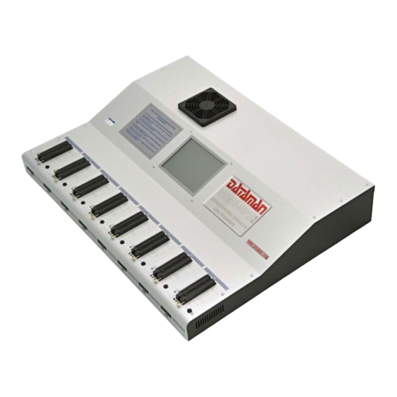
- Page 1 User manual for DATAMAN-848PRO2 Extremely fast universal 8x 48-pindrive Stand-Alone concurrent multiprogramming system Internal PC is driven by Microsoft Windows XP Embedded September 2017...
- Page 2 This document is copyrighted by Dataman Programmers Ltd, United Kingdom. All rights reserved. This document or any part of it may not be copied, reproduced or translated in any form or in any way without the prior written permission of Dataman Programmers Ltd.
-
Page 3: Table Of Contents
Table of contents Introduction ..........................4 DATAMAN-848PRO2 elements....................6 Manipulation with the programmed device................7 In-system serial programming by DATAMAN-848PRO2 ............7 Selftest .............................10 Technical specification ......................11 Programming a device ......................18 Engineering mode ........................18 Production mode ........................22 Software ............................25 Detailed description of Graphics user interface with touch screen........25 Administration of build in PC....................42... -
Page 4: Introduction
The operator merely removes the finished chip and inserts a new chip. Operator training is therefore minimized. DATAMAN-848PRO2 supports all kinds and types of silicon technology found in today’s and tomorrows programmable devices without family specific modules. You can be sure... - Page 5 As a result, when used in production this programmer waits for an operator, and not the other way round. DATAMAN-848PRO2 provides the two banana jacks, one for ESD wrist strap connection for easy-to-implement ESD protection and the second one for connection to ground.
-
Page 6: Dataman-848Pro2 Elements
It is important to remember that in most cases new devices require only a software update because the DATAMAN-848PRO2 is based on the truly universal (DATAMAN- 48PRO2) programmer. With our prompt service you can have new devices added to the... -
Page 7: Manipulation With The Programmed Device
(turn off programmer), but the content of programmed cells may remains undefined. Don't unplug the target device from the ZIF socket during work with device (BUSY LED on). In-system serial programming by DATAMAN- 848PRO2 Optimized advanced pindrivers deliver programming performance without overshoot or ground bounce for all device technologies. - Page 8 The software provides full information for ISP implementation: Description of ISP connector pins for currently selected chip, recommended target design around in-circuit programmed chip and other relevant information. For general definition, recommendation and direction about ISP see section Common notes / ISP please. Description of ISP connector Front view at ISP connector.
- Page 9 Use only attached ISP cable. When you use other ISP cable (other material, length…), programming may become unreliable. DATAMAN-848PRO2 can supply programmed device (pin 1 of ISP connector) and the target system (pin 19 and 20 of ISP connector) with some limitations. (see...
-
Page 10: Selftest
DATAMAN-848PRO2 apply programming voltage to target device and checks his value (target system can modify programming voltage). If the programming voltage is different from expected, no action with target device will be executed. Selftest Warning: Selftest can be run in engineering mode only. -
Page 11: Technical Specification
Technical specification Specification (DATAMAN-848PRO2 multiprogramming system) 8x universal programming module (8x 48-pin DIL ZIF sockets and 8x ISP connector) operation result LEDs, LED power line power input 100-240VAC/60W max. banana jack for ESD wrist straps connection banana jack for connection to ground... - Page 12 target system supply voltage (range 2V..6V/250mA) ESD protection on each pin of ISP connector (IEC1000-4-2: 15kV air, 8kV contact) two output signals, which indicate state of work result = LED OK and LED Error (active level: min 1.8V) input signal, switch YES! equivalent (active level: max 0.8V) DEVICE SUPPORT (valid for each programming module) Programmer NAND FLASH: Samsung K9xxx, KFxxx, SK Hynix (ex Hynix) HY27xxx, H27xxx,...
- Page 13 FPGA: FPGA: Microsemi(Actel): ProASIC3, IGLOO, Fusion, ProASICplus, SmartFusion FPGA: Lattice: MachXO, MachXO2, LatticeXP, LatticeXP2, ispXPGA FPGA: Xilinx: Spartan-3AN Clocks: TI(TMS), Cypress Special chips: Atmel Tire Pressure Monitoring ATA6285N, ATA6286N; PWM controllers: Zilker Labs, Analog Devices; Multi-Phase ICs: IR(Chil Semiconductor); Gamma buffers: AUO, Maxim, TI, ... Microcontrollers MCS51 series: 87Cxxx, 87LVxx, 89Cxxx, 89Sxxx, 89Fxxx, 89LVxxx, 89LSxxx, 89LPxxx, 89Exxx, 89Lxxx, all manufacturers, Philips LPC series Microcontrollers Intel 196 series: 87C196 KB/KC/KD/KT/KR/...
- Page 14 * are obsolete, can be programmed with PLD-1 additional module or 2708 additional module For all supported devices see actual Device list at www.dataman.com Programmer, through ISP connector Serial E(E)PROM: IIC series, MW series, SPI series, KEELOQ series, PLD...
- Page 15 FPGA: Microsemi(Actel): ProASIC3, IGLOO, Fusion, ProASICplus, SmartFusion FPGA: Lattice: MachXO, MachXO2, LatticeXP, LatticeXP2, ispXPGA Notes: For all supported devices see actual Device list at www.dataman.com. Package support support all devices in DIP with default socket package support includes DIP, SDIP, PLCC, JLCC, SOIC, SOP, PSOP, SSOP, TSOP, TSOPII, TSSOP, QFP, PQFP, TQFP, VQFP, QFN (MLF), SON, BGA, EBGA, FBGA, VFBGA, UBGA, FTBGA, LAP, CSP, SCSP etc.
- Page 16 Programming speed Device Size [bits] Operation Time K8P6415UQB (parallel NOR Flash) 400100Hx16 (64 Mega) programming and verify 13 sec MT29F1G08ABAEAWP (parallel NAND Flash) *2 8400000Hx8 (1 Giga) programming and verify 51 sec THGBM3G4D1FBAIG (eMMC NAND Flash) *2 2048 MB x8 (16 Giga) programming *1 363 sec QB25F640S33 (serial Flash)
- Page 17 5°C ÷ 35°C (41°F ÷ 95°F) humidity 20%..80%, non condensing Package included Standard accessories DATAMAN-848PRO2 programmer diagnostic POD for ZIF socket selftest of the programmer (1x) diagnostic POD for ISP connector selftest of the programmer (1x) ISP cable (8x)
-
Page 18: Programming A Device
It is the same time-proven software, as is used for other Dataman single-site programmers. Engineers can use all properties of this software and can make a project for mass production. - Page 19 Make a project Connect external display, keyboard and mouse to PC connectors on back side of programmer Turn on programmer. Run the control program: double click on icon. Find DATAMAN-848PRO2 Site (programmer): <Ctrl+F> or right click on panel Programmer...
- Page 20 Select DATAMAN-848PRO2, Site and then click on “Connect” button. Select site. Select desired DATAMAN-848PRO2 Site# and then click on “OK” button Select device: click on icon and select desired device...
- Page 21 Load data into buffer from file: click on icon. Set Device operation options Set desired operations for the device and then click on “OK” button To customize device use menu <Alt+S> Set desired settings for the device and then click on “OK” button...
-
Page 22: Production Mode
You can make a project on other DATAMAN programmers (DATAMAN-48PRO2…) too. For more details see Help for PG4UW or “Dataman PRO series_manual”. The latest manual may be found at www.dataman.com. Production mode Warning: External display, keyboard and mouse not needed in this mode. - Page 23 Checking if the sites are ready to be connected When first starting Stand-Alone multiprogramming system, or when error message “Programmer Sites not found” is displayed, then programmer software must be reinitialized by action “Search for Programmers...” available in menu “Programmer / Search for Programmers...”. In dialog Search for Programmers use button “Search”...
- Page 24 predefined operation is “Program device“, the caption of button Run will be “Run Program“. 18. Selected device operation including sub-operations that are part of predefined device operation will start. Progress of operations is displayed in panel status for each programmer site. You can use some special features of Stand-Alone multiprogramming system, for example Count down or Statistics.
-
Page 25: Software
Software Detailed description of Graphics user interface with touch screen Wait please screen Wait please screen is displayed on standalone's built-in LCD screen as the first screen after turning-on power. The screen is shown during booting up of operating system and starting of standalone control software PG4UWMC. - Page 26 LCD main screen Main screen consists of following parts: Menu: File Device Programmer Options Help Table with information about programmer sites (site and serialization status) Next serial value Statistics Recently selected device name Recent project name Checksum of data stored in data buffer for currently selected device button Run...
- Page 27 Next serial value When serialization is active, the panel displays current serialization mode and serialization number or label that will be used for next device programmed. Recent serial numbers used for each device are displayed in table Site and serialization status in column Serialization.
- Page 28 When option 1 is selected, dialog with list of project files present in [Projects] folder will appear. User can select desired project and load the project by clicking on 'Load' button. Dialog can be closed by 'Cancel' button. Also basic information about selected project file can be displayed by clicking 'File info' button.
- Page 29 When option 1 is selected, the dialog with list of project files at specified drive and folder will appear. User can select desired drive, folder and project file and copy the selected project to the [Projects] folder by clicking on 'Copy' button. 'Change dir' button is used to change current directory to directory selected in 'Directory' list on the left side of dialog.
- Page 30 File / Switch to Engineering mode Command is used to start PG4UW control program in Engineering mode. In this mode, user can use PG4UW software to select any device from the list of supported devices, set options for the device, load data files for device, test the device operations on any programmer site and create a project file which can be used in production mode.
- Page 31 Situations, when the command is useful are: 1. when first starting DATAMAN-848PRO2 Stand-Alone multiprogramming system 2. when error message “Programmer Sites not found” is displayed In the dialog “Search Programmers” use button “Search” to search for attached programmers.
- Page 32 If search result is “No Programmers found”, please try to turn off Stand-Alone programmer, by menu “File / Shut down computer”, turn off the power button on the back side of programmer, wait for 15 seconds or more and start programmer again. If the search result is still “No Programmers found”, please refer to troubleshooting documentation.
- Page 33 When Automatic YES! mode is On, programmer sites are scanning their device sockets after device operation is completed. The control program can detect removing of programmed device and insertion of new device and afterwards automatically start (repeat) recent operation on new device. So operator does not need to press any key or button, to program next device.
- Page 34 Menu Options Options / Switch to Operator Mode... Switch to Administrator Mode Program PG4UWMC is set by default to Administrator Mode. It means, no operation blocking for user is applied. But in production, there is suitable to block some menu commands, to ensure, user does not modify important program settings or configuration.
- Page 35 project load. To enable Load project command again, Administrator Mode of PG4UWMC must be entered. To switch program from Operator Mode back to Administrator Mode, use the menu command Options / Switch to Administrator Mode... The "Password required" dialog appears. User has to enter the same password as the password entered during switch to Operator Mode.
- Page 36 Log file... Log files settings screen looks as following: Log file is text file containing information about PG4UWMC control program operation flow, which means information about loading project files, device operation types and device operation results. Main Log file name in Stand-Alone programmer can not be modified by user, it has defined value E:\Logs\reportmc.log where drive E: is placed on built-in disk of Stand- Alone programmer.
- Page 37 < log_file_name><-yyyy-mmm-dd>.<log_file_extension> The new part representing the date consists of yyyy - year, mmm - month and dd - day. Example: Log file name is E:\Logs\reportmc.log The final log file name with added date will look like this (July, 7th, 2007): E:\Logs\reportmc-2007-jul-07.log Advanced options about Log file size limit: option Use Log file text truncating when file size limit is reached - when...
- Page 38 Display backlight allows user to control backlight intensity. Border style offers options to set color for unused part of LCD screen (left and right borders). Touchpad calibration... Command is used for calibration of built-in touch pad, part of built-in LCD touch screen. The calibration of touchpad is recommended if you encountered unexpected reactions from touchpad.
- Page 39 Options / Statistics... Command displays dialog “Statistics”. Statistics gives the information about actual count of device operations, which were proceeded on selected type device. If one device is corresponding to one device operation, e.g. programming, the number of device operations will be equal to the number of programmed devices. Statistics dialog contains following options: Check boxes: Program, Verify, Blank and Erase which define operations, after which statistics values increment.
- Page 40 Options / View Log... Command displays content of current Log window. At top right corner is the button [x], which is used for closing the Log window and displaying of main screen. Options / Reset all settings... When menu Reset all settings is used, Password required dialog will appear, and user will be prompted to enter randomly generated number.
- Page 41 Help / Update software... This important menu command allows users to make software updates. After selecting this item, program will display question “Are you sure?”. If user confirms the question with answer Yes, dialog “Select installation package” will be displayed. In this dialog user can browse for the “pg4uwarc”...
-
Page 42: Administration Of Build In Pc
Windows XP Embedded operating system (“OS”). There are two major kinds of administration of the OS – network and local. OS is configured with two users accounts admin operator. Credentials for DATAMAN-848PRO2 Stand-Alone multiprogramming system users are: Login Password Administrator admin... - Page 43 Remote control Administering of DATAMAN-848PRO2 Stand-Alone multiprogramming system is performed through Microsoft “Remote Desktop Connection”. Remote desktop offers fast and comfortable way to update software (control software and system), distribute project files ... Find and run “Remote Desktop Connection” program on your computer. In “Computer”...
- Page 44 "runas" command from operator account, or login as admin). perform restart DATAMAN-848PRO2 system. make desired changes in your DATAMAN-848PRO2 system. run "fbwfmgr.exe /enable", and restart DATAMAN-848PRO2 immediate. Now should be changes permanent (until system recovery will be performed). Operating system recovery Recovery OS performs refreshing of programmer operating system to state as it was shipped from factory.
- Page 45 With arrow keys (up or down) select “Windows Recovery” and press Enter. Recovery system will be started. Please be patient. This can take about four minutes. Then EULA license will show. Please read carefully this license agreement, close window, press “A” if you accept this agreement. Accepting agreement starts formatting of disk D:, and installation of control program (recovery deletes Programmer directory on disk E:, and creates new one).
-
Page 46: Troubleshooting And Warranty
Include everything that you consider being relevant about the programmer, software and the target device. Send the completed form by mail or fax to DATAMAN (fax number in the control program, menu Help / About) or to your local dealer. -
Page 47: If You Have An Unsupported Target Device
Because DATAMAN-848PRO2 have internal power supply, follow these special precautions: Circuit breakers (overcurrent protection) must be a part of building electrical installation. -
Page 48: Maintenance
Maintenance We recommend following the instructions and precautions herein to achieve high reliability of the programmer for a long period of time. The programmer maintenance depends on character and amount of its use. Regardless, the following recommendations are generally accepted: Do not use and store the programmer in dusty places. -
Page 49: Warranty Terms
The warranty does not apply to products that are of wear and tear or mechanically damaged. Equally, the warranty does not apply to products opened and/or repaired and/or altered by personnel not authorized by Dataman, or to products that have been misused, abused, accidentally damaged or that were improperly installed.
Need help?
Do you have a question about the DATAMAN-848PRO2 and is the answer not in the manual?
Questions and answers