Table of Contents
Troubleshooting

Related Manuals for Dataman 448PRO2AP


Summary of Contents for Dataman 448PRO2AP
- Page 1 User manual for DATAMAN 448PRO2AP Super fast universal 4x 48-pindrive concurrent multiprogrammer – core automated programmer DATAMAN 48PRO2AP Super fast universal 48-pindrive programmer – core for automated programmer...
- Page 2 Dataman Programmers Ltd. The control program is copyrighted by Dataman Programmers Ltd. The control program or any part of it may not be analyzed, disassembled or modified in any form, on any medium, for any purpose.
-
Page 3: How To Use This Manual
HELP within the control program rather than the printed User manual. Revisions are implemented in the context sensitive help before the printed User manual. ___________________________________________ We continuously update our manual. You may find the latest version from our website (www.dataman.com). -
Page 4: Table Of Contents
PC requirements ..........................8 Free additional services: ........................9 DATAMAN 448PRO2AP ........................10 Introduction ............................11 DATAMAN 448PRO2AP elements ....................13 Connecting DATAMAN 448PRO2AP to the PC ................14 Selftest ............................... 14 Technical specification ........................16 DATAMAN 48PRO2AP ......................... 17 Introduction ............................18 DATAMAN 48PRO2AP elements ..................... - Page 5 Conventions used in the manual References to the control program functions are in bold, e.g. Load, File, Device, etc. References to control keys are written in brackets <>, e.g. <F1>. Terminology used in the manual: Device any kind of programmable integrated circuits or programmable devices ZIF socket Zero Insertion Force socket used for insertion of target device Programmer...
-
Page 6: Introduction
Introduction... -
Page 7: Products Configuration
Advanced design, including protection circuits, original brand components and careful manufacturing allows us to provide a three-years warranty for DATAMAN 448PRO2AP and DATAMAN 48PRO2AP on parts and labor for the programmers (limited to 500 insertion of programming module to Programming Module Interface connectors). This warranty terms are valid for customers, who purchase a programmer directly from Dataman company. -
Page 8: Pc Requirements
If you find any discrepancy with respective parts list and/or if any of these items are damaged, please contact your distributor immediately. PC requirements Minimal PC requirements 2x DATAMAN 448PRO2AP 1000 DATAMAN 448PRO2AP 1000 ... -
Page 9: Free Additional Services
(Ctrl+Alt+Del) and see the performance folder. It has to be max. 80% of CPU usage at full run of programming system. Free additional services: free technical support (phone/fax/e-mail). free lifetime software update via Web site. Free software updates are available from our Internet address www.dataman.com. -
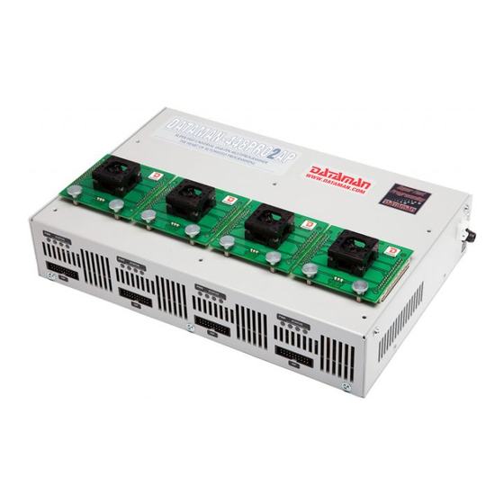
Page 10: Dataman 448Pro2Ap
DATAMAN 448PRO2AP... -
Page 11: Introduction
The DATAMAN 448PRO2AP control unit is Windows XP Embedded driven computer, optimized for industrial environment. One DATAMAN 448PRO2AP control unit in the system serve as a master unit. Here is running also multiprogramming control software, serialization engine and interface to the host system. - Page 12 It is important to remember that in most cases new devices require only a software update due to the DATAMAN 448PRO2AP is truly universal programmer. With our unique quick reaction to customer's needs - software update can be ready within a day from request by...
-
Page 13: Dataman 448Pro2Ap Elements
7. programming module fixating screws 8. right site power supply connector 9. right site type B USB connector for PC DATAMAN 448PRO2AP communication cable 10. right site tie mount for fixating USB cable Right top view to DATAMAN 448PRO2AP... -
Page 14: Connecting Dataman 448Pro2Ap To The Pc
11. rear site power supply connector 12. rear site type B USB connector for PC DATAMAN 448PRO2AP communication cable 13. rear site tie mount for fixating USB cable 14. temperature controlled fans 15. "GND" screw can be used for grounding of the programmer... - Page 15 DATAMAN 448PRO2AP AP1 PMI selftest pod Selftest of ISP connector Insert AP1 ISP connector selftest pod into Programmer Module Interface (PMI) connectors of the programmer. Interconnect 20 pins connector of AP1 ISP connector selftest pod with an ISP connector of the programmer with an ISP cable, included in delivery programmer package.
-
Page 16: Technical Specification
dimensions: 310x205x61 mm (12.2 x 8.1 x 2.4 inch). Dimensions were measured without programming module inserted and does not include projections. Total height of DATAMAN 448PRO2AP programmer with programming module inserted depends on ZIF socket height and can vary between 80-90mm. -
Page 17: Dataman 48Pro2Ap
DATAMAN 48PRO2AP DATAMAN 48PRO2AP... -
Page 18: Introduction
ISP programmer identically as DATAMAN 48PRO2 programmer - using of standard PC. DATAMAN 48PRO2AP can be connected to the control PC of automated programmer too. Up to 8 DATAMAN 48PRO2AP can be attached to one computer using USB hub or USB ports of the PC Implementation of DATAMAN 48PRO2AP into available 3rd party automated programmers and handlers is using simple remote control of the PG4UWMC control software. - Page 19 It is important to remember that in most cases new devices require only a software update due to the DATAMAN 48PRO2AP is truly universal programmer. With our unique quick reaction to customer's needs - software update can be ready within a day from request by...
-
Page 20: Dataman 48Pro2Ap Elements
2. work result LEDs 3. power/sleep LED of site 4. ISP connector (20 pins connector 2-1634689-0 from TE connectivity) 5. M4 nuts for fastening DATAMAN 448PRO2AP to upper plate 6. programming module fixating screws Right top view to DATAMAN 48PRO2AP... -
Page 21: Connecting Dataman 48Pro2Ap To The Pc
DATAMAN 48PRO2AP 7. power supply connector 8. type B USB connector for PC DATAMAN 448PRO2AP communication cable 9. tie mount for fixating USB cable 10. temperature controlled fan 11. "GND" screw can be used for grounding of the programmer... - Page 22 AP1 PMI selftest pod Selftest of ISP connector Insert AP1 ISP connector selftest pod into Programmer Module Interface (PMI) connectors of the programmer. Interconnect 20 pins connector of AP1 ISP connector selftest pod with an ISP connector of the programmer with an ISP cable, included in delivery programmer package.
-
Page 23: Multiprogramming By Dataman 48Pro2Ap
For start of DATAMAN 48PRO2AP multiprogramming is necessary run special control program pg4uwmc.exe. At this program user assign DATAMAN 48PRO2AP to control programs, may load projects for all DATAMAN 48PRO2AP and run PG4UW for every connected and assigned DATAMAN 48PRO2AP. -
Page 24: Setup
Setup... -
Page 25: Software Setup
The programmer package contains a CD with the control program, useful utilities and additional information. The permission to freely copy the content of the CD is granted in order to demonstrate how DATAMAN’s programmers work. For programmers connected through USB port, control program requires correctly installed... - Page 26 Step 2. Click on “Next” button Step 3. For default setting click on “Next” button. Setup will be continuing with Step 6. For change default setting click on “Custom” and then on “Next” button.
- Page 27 Setup Step 4. For change default folder click on “Browse” button, select the destination folder. Then click on “Next” button Step 5. For change default folder click on “Browse” button, select the destination folder. Then click on “Next” button...
- Page 28 Step 6. Check if “Install Multiprogramming control support” is selected. Change default setting, if you want. Then click on “Next” button Step 7. Check your setting and then click on “Install” button...
- Page 29 Setup Step 8. Installation process will start. Step 9. Click “Finish” button to finish setup.
-
Page 30: Hardware Setup
In order to exploit all the capabilities of programmer we recommend using the latest version of PG4UW. You may download the latest version of programmer software from our website www.dataman.com. Copy pg4uwarc.exe to a temporary directory, disconnect programmer from PC and then launch it. - Page 31 Setup For Windows 7 and Windows 8. Step 5. In the notification area at task bar (mainly at lower right corner) you will see following notification bubble: After successfully installed driver for programmer you will see Note: If another programmer will be connected to PC (maybe to the same USB port) “Installing device driver software”...
- Page 32 Select “No, not this time” and then click on “Next” button. For all: Select “Install the software automatically” and then click on “Next” button. Step 6. Wizard start searching programmer and start install driver automatically. Step 7. After successfully installing of programmer you will see following window:...
- Page 33 Step 8. “Found new hardware wizard” will launch for each programmer (programmer site) one time (for DATAMAN 448PRO2AP-AU and DATAMAN 448PRO2AP 4 times). Setup will be continued with Step 5. Note: If a different USB port on the PC is used for the next connection of programmer, “Found...
- Page 34 DATAMAN 48PRO2AP to target system. DATAMAN 448PRO2AP On picture bellow are overall dimensions of DATAMAN 448PRO2AP with programming modules. Total height of programmer with installed programming modules depends of programming module ZIF socket height. Total height can be determined by 68,5mm + ZIF socket height.
- Page 35 Setup If USB connector and power cable are connected to rear connectors, total depth of programmer will be 205mm + length of B type USB connector on USB cable. Total depth of programmer may be 205mm + 50mm. If USB connector and power cable are connected to right side connectors, total width of programmer will be 310mm + length of B type USB connector on USB cable.
- Page 36 DATAMAN 448PRO2AP can be mounted on base plate by 6 screws M4 with nuts. Length of screw depends on base plate thickness. On base plate can be ø 4,5mm holes replaced with M4 internal threads. Drawing for mounting programmer on base plate:...
- Page 37 Setup DATAMAN 448PRO2AP can be mounted bellow base plate by 6 screws M4. Length of screw depends on base plate thickness. Attentions: For proper mounting of programmer bellow base plate, mounting screws must be minimal 3mm depth in programmer. To avoid damage of PCB in programmer mounting screws must be maximum 8mm depth in programmer.
- Page 38 DATAMAN 48PRO2AP On picture bellow are overall dimensions of DATAMAN 48PRO2AP with programming module. Total height of programmer with installed programming modules depends of programming module ZIF socket height. Total height can be determined by 68,5mm + ZIF socket height.
- Page 39 Setup USB connector and power cable are connected to rear connectors, total depth of programmer will be 205mm + length of B type USB connector on USB cable. Total depth of programmer may be 205mm + 50mm. Mounting USB cable to case and length of USB connector with cable bending. For proper connection DC adapter to programmer, arrow on cable connector must be oriented to arrow on programmer connector.
- Page 40 DATAMAN 48PRO2AP can be mounted on base plate by 2 screws M3. Length of screw depends on base plate thickness. Attention: For proper mounting of programmer on base plate, mounting screws must be minimal 3mm depth in programmer. To avoid damage of PCB in programmer mounting screws must be maximum 8mm depth in programmer.
- Page 41 Setup DATAMAN 48PRO2AP can be mounted bellow base plate by 4 screws M4. Length of screw depends on base plate thickness. Attention: For proper mounting of programmer on base plate, mounting screws must be minimal 3mm depth in programmer. To avoid damage of PCB in programmer mounting screws must be maximum 8mm depth in programmer.
- Page 42 DATAMAN 48PRO2AP can be mounted with left side on base plate by 4 screws M3. Length of screw depends on base plate thickness. Attention: Before mounting DATAMAN 48PRO2AP in this way, unscrew two screws M3 located on left side. Then replace them with new M3 screws with proper length. For proper mounting of programmer on base plate, mounting screws must be minimal 3mm depth in programmer.
- Page 43 PG4UW PG4UW...
-
Page 44: Pg4Uw-The Programmer Software
In Windows environment: double click to icon PG4UW. After start, control program PG4UW automatically scan all existing ports and search for the connected any DATAMAN programmer. Program PG4UW is common for all the DATAMAN programmers, hence program try to find all supported programmers. - Page 45 PG4UW Description of the user screen Windows program PG4UW Toolbars Under main menu are placed toolbars with button shortcuts of frequently used menu commands. Toolbars are optional and can be turned off by menu command Options / View. Log window Log window contains the flow-control progress information about almost every operation made in PG4UW.
- Page 46 Panel Addresses Panel Addresses contains information about actual address ranges of currently selected device, loaded file and buffer start-end address settings. Some devices allow modifying default device and buffer address ranges by menu command Device / Device options / Operation options.
-
Page 47: File
PG4UW <F1> Help Calls Help <F2> Save Save file <F3> Load Load a file into the buffer <F4> Edit Viewing/editing of buffer <F5> Select/default Target-device selection from 10 last selected devices list <Alt+F5> Select/manual Target-device selection by typing device/vendor name <F6>... - Page 48 ASCII SPACE format Very simple hex file format similar as ASCII HEX without checksum field, without start (STX) and end (ETX) characters. Each data byte is represented as 2 hexadecimal characters, and is separated by white space from all other data bytes. The address field is separated by white space from data bytes.
- Page 49 PG4UW Note: Big-endian and little-endian are terms that describe the order in which a sequence of bytes are stored in computer memory. Big-endian is an order in which the "big end" (most significant value in the sequence) is stored first (at the lowest storage address). Little-endian is an order in which the "little end"...
- Page 50 PICmicro devices. For these special devices, there are available only manual offset settings (None, Positive offset, Negative offset). Example for negative offset using: A file contains data by Motorola S - format. A data block started at address FFFF0H. It is a S2 format with length of address array of 3 bytes. For all data reading you can set Negative offset option and value of negative offset to FFFF0H.
- Page 51 PG4UW File / Load project This option is used for loading project file, which contains device configuration buffer data saved and user interface configuration. The standard dialog Load project contains additional window - Project description - placed at the bottom of dialog. This window is for displaying information about currently selected project file in dialog Load project.
- Page 52 It contains two editable fields: Operator identification this parameter will be used to identify programmer's operator. Operator ID must be at least 3 chars. User has to enter Operator identification value, because it is mandatory parameter, when creating Job Report for protected project. ...
- Page 53 PG4UW Note: Option Require project file unique ID before first programming is replacement of former Require project file checksum before first programming. Unique ID advantage over generic checksum is that unique ID is calculated not just from main device buffer data, but also from secondary buffers data used by device and available device settings.
-
Page 54: Buffer
File / Save encryption table This command writes the content of the memory's part, reserved for an encryption table, into the file on the disk as a binary data. File / Exit without save The command deallocates heap, cancels buffer on disk (if exists) and returns back to the operation system. - Page 55 PG4UW swap bytes command swaps a high- and low- order of byte pairs in current buffer block. This block must start on even address and must have an even number of bytes. If these conditions do not fulfill, the program modifies addresses itself (start address is moved on lower even address and/or end address is moved on higher odd address).
- Page 56 Direction box specifies which way you want to search, starting from the current cursor position (In edit mode). Forward (from the current position or start of buffer to the end of the buffer) is the default. Backward searches toward the beginning. In view mode searches all buffer. Origin specifies where the search should start.
- Page 57 PG4UW Note: Address history values are common for all buffer data manipulation dialogs. Default address range is set according to buffer range of selected device. Selecting option "Maintain last inserted values" causes that for the next time you open this dialog, previously confirmed values will be reloaded as default.
- Page 58 Swap 2-bytes Swap 4-bytes Swap Mirror bits Original Address inside 16-bit inside 32-bit nibbles inside Data words words inside bytes bytes 0000h 0001h 0002h 0003h 0004h 0005h 0006h 0007h b0, b1, b2 ... means original buffer byte values from addresses 0, 1, 2... b0n, b1n, b2n ...
- Page 59 PG4UW Default address range is set according to buffer range of selected device. Selecting option "Maintain last inserted values" causes that for the next time you open this dialog, previously confirmed values will be reloaded as default. The reserved key <Shift+Ctrl+F2> will bring out this menu from any menu and any time. Buffer / Duplicate buffer content This command performs duplicate buffer content in range of source EPROM to range of destination EPROM.
- Page 60 Size Size of chosen checksum result, which will be written into the buffer. A size of inserted checksum may be Byte (8-bit), Word (16-bit) or DWORD (32-bit). If size is smaller then selected checksum size, only lower byte(s) of checksum value will be written into the buffer. Note: If Word size was selected, a low byte of checksum value will be written on address specified in box Insert address and a high byte will be written on address incremented by one.
-
Page 61: Device
PG4UW Word sum Big Endian (x16) Buffer data are summed word-by-word irrespective of current buffer view mode organization. Any carry bits exceeding 32-bits are neglected. This checksum mode is indicated by string (x16 BE) displayed after checksum value in main program window. Term Big Endian means, the buffer checksum is calculated from words read from buffer in Big Endian mode. - Page 62 If you wish display additional information about the current device, use an <Ctrl+F1> key. This command provides a size of device, organization, programming algorithm and a list of programmers (including auxiliary modules) that supported this device. You can find here package information and other general information about current device too.
- Page 63 PG4UW Select device ... / All This window allows selecting the desired type of the device from all devices supported by current programmer. Supported devices are displayed in a list box. Device can be select by double click on a line from list with desired manufacturer name and device number or by entering manufacturer name and/or device number in a search box (use a key <Space>...
- Page 64 If you wish display additional information about the current device, use button Device info or an <Ctrl+F1> key. This command provides a size of device, organization, programming algorithm and a list of programmers (including auxiliary modules) that supported this device. You can find here package information and other general information about current device too.
- Page 65 PG4UW List of commonly used items: group Addresses: device start address (default 0) device end address (default device size-1) buffer start address (default 0) Split (default none) This option allows setting special mode of buffer when programming or reading device. Using split options is particularly useful when using 8-bit data memory devices in 16-bit or 32-bit applications.
- Page 66 Notes: Some old chips don't carry electronic ID. In some special cases, several microcontrollers don't provide ID, if copy protection feature in the chip is set, even if device ID check setting in control program is set to "Enable". group Command execution: blank check before programming (default DISABLE) erase before programming...
- Page 67 PG4UW Supply voltage (in mV) - supply voltage in target system. Control program checks or sets (it depends on programmer type) entered supply voltage in target system before every action on device. Disable test supply voltage - disables measure and checking supply voltage of programmed device, set in Supply voltage edit box, before action with device.
- Page 68 serialization settings for recent device are saved along with other settings of the device to project file or to configuration file when application is closed serialization engine calls request for new (next) serial number before each device programming is started ...
- Page 69 PG4UW S / N mode S / N mode option defines the form in which serial value has to be written to buffer. Two options are available: ASCII Bin ASCII - means the serial number is written to buffer as ASCII string. For example number $0528CD is in ASCII mode written to buffer as 30h 35h 32h 38h 43h 44h (‘0’...
- Page 70 Mode: Incremental mode S/N size: 4 bytes S/N mode: Bin Style: Hex Save to buffer: LS Byte first Address: 7FFFCH Start value: 16000000H Step: 1 Following values will be written to device: The 1st device Address Data 007FFF0 xx xx xx xx xx xx xx xx xx xx xx xx 00 00 00 16 The 2nd device Address Data...
- Page 71 PG4UW Description 14-Bit word RETLW Return with literal in W 01xx kkkk kkkk where xx can be replaced by 00 and k are data bits, i.e. serial number byte Opcode of RETLW instruction is hexadecimal 34KKH where kk is data Byte (serial number byte) Let’s assume we want to write serial number 1234ABCDH as part of four RETLW instructions to device PIC.
- Page 72 Split settings described above mean split of serial number by bytes to buffer at every second byte. The correct serial number is set tightly before device programming operation starts. The buffer content of serial number when programming the first device will be: Address Data 0000040...
- Page 73 PG4UW Address Data 0000800 56 34 00 00 12 00 00 00 xx xx xx xx xx xx xx xx The second device will have: Address Data 0000800 57 34 00 00 12 00 00 00 xx xx xx xx xx xx xx xx Next devices will have same format of serial number incremented by 1 for each device.
- Page 74 Device / Device options / Serialization / Classic From file mode When you use a Classic From-file mode the serialization file has serial values directly included. Serialization data are then read directly from serialization file to buffer on address specified in the file. Classic From-file mode is indicated in main window and info window of PG4UW control program on panel "Serialization"...
- Page 75 PG4UW The process of writing particular bytes to buffer is: byte0 to addr byte1 to addr + 1 byte2 to addr + 2 ..byten to addr + n Optional part is delimited from the first data part by character “,“ (comma) and its structure is the same as in the first data part, i.e.
- Page 76 org. (x8), the Serialization Address will be byte address. If the buffer organization is wider than byte, e.g. 16 bit words (x16); the Serialization Address will be word address. Device / Device options / Serialization / Playlist From file mode When you use a Playlist From-file mode the serialization file has not serial values directly included.
- Page 77 PG4UW The typical path can look like this: C:\Program Files\DATAMAN_sw\Programmer\Examples\Serialization\fromfile_playlist_example\ You can test the serialization by following steps: 1. start PG4UW 2. you need to have our programmer connected and correctly found in PG4UW 3. select wished device, the best are devices with erasable memory, (not OTP memory) 4.
- Page 78 Examples: There are also example .exe and C/C++ source files available. The files are placed in the PG4UW installation directory in Examples\ subdirectory as following: <PG4UW_inst_dir>\Examples\Serialization\customgenerator_example\ The typical path can look like this: C:\Program Files\DATAMAN_sw\Programmer\Examples\Serialization\customgenerator_example\ There are following options for Custom generator serialization in PG4UW control software: In dialog Serialization select in Mode panel option Custom generator mode.
- Page 79 PG4UW -N<serial number> specifies current serial number in the same way, as for normal calling of serialization generator. Custom generator program Custom generator program or serialization generator is program that will generate the unique sequence of serial numbers and write the serial data to serialization .dat file. This program is made by user.
- Page 80 Example: Typical serialization data file: T01:000005 T02:001006 T03:99 T04: :0300000000096B89 :03000300000005F5 :02000C005A0197 :01003F004F71 :00000001FF The file consists of following information: line T01 - current serial number 000005h line T02 - ending (last) serial number 001006h line T03 - serialization data format after line T04 is Intel Hex line T04 - serialization data, which will be loaded to buffer of PG4UW before programming device, data are represented in Intel Hex format Optional records are:...
- Page 81 PG4UW 5. Device verification 6. Operation result check. This is fully managed by PG4UW control program. Serialization generator does not have to do any operation according to operation result. Control program will call serialization generator with required command line parameters. OK - PG4UW makes request for next serial number.
- Page 82 Statistics dialog contains seven statistics values – Success, Operational failure, Adapter test failure, Insertion test failure, ID check failure, Other failure (prog. SW, HW) and Total. Meaning of the values is: Success number of operations which where successfully completed Operational failure number of operations which where not successfully completed due to error of device Adapter test failure...
- Page 83 PG4UW You can edit the associated file name in file name box, put a full pathname. The control program checks the present of this file on the disk. Also is possible enabling or disabling automatic load of this file. You can save both settings i.e. associated file and enabling of automatic load of this file to disk by command File / Exit and save.
- Page 84 Notes: Verify operation compares content of the whole chip with the data in the software, therefore it might happen - in case of incomplete programmed chip - the verification after programming shows none error, but solo verify operation does not pass. ...
- Page 85 PG4UW Notes: It is possible to select a delay between write operation and succeeding verify of programmed data (at condition the device is supplied) in intent to detect 'leak' of the bits. Programmer hasn’t capability to detect errors like too big current on the signal pins or such "analog"...
- Page 86 The devices can be programmed in ZIF socket of the programmer or in target system through ISP connector. It is indicated by [PLCC44] (Jam) or (ISP-Jam) suffix after name of selected device in control program. Multiple devices are possible to program and test via JTAG chain: JTAG chain (ISP-Jam) More information on the website: http://www.altera.com...
- Page 87 PG4UW Jam Player version 2 (see Action and Procedures controls) Action Select desired action for executing. Jam file of version 2 consists of actions. Action consists of calling of procedures which are executed. Jam file of version 1 does not know statements 'action' and 'procedure', therefore choice Action is not accessible.
- Page 88 JAM file information dialog Note: Statements are used to store information about the Jam file. The information stored in NOTE fields may include any type of documentation or attributes related to the particular Jam program. Source file contains a program in Jam language. Jam program consists of a sequence of statements.
- Page 89 PG4UW choose “Device operation option Alt+O” press button “Jam configuration”. Warning “Select device from menu "Select Devices" and Jam file is probably different! Continue?” choose Yes. (Xilinx sw. does not include line: NOTE "DEVICE" "XC2x32A"; in Jam file). In dialog “Jam player”...
- Page 90 Frequently asked questions about Actel Q: How can be identify/verify already programmed Actel device? A: There are several possible options to get this done. Each option (action) is varying from each other in method of comparing already programmed Actel device with loaded STAPL file.
-
Page 91: Programmer
PG4UW The reserved key <Ctrl+F1> will bring out this menu from any menu and any time immediately. Programmer Menu Programmer includes commands used for work with programmers. Programmer / Find programmer This item selects a new type of programmer and communication parameters. This command contains following items: Programmer - sets a new type of programmer for find. - Page 92 Programmer / Handler In dialog Handler a Handler type and Handler communication parameters can be set. Handler is an external device for special control of device operations in control program. When None Handler is selected, this means default state of control program, i.e. device operations are controlled directly by user otherwise control program is in special mode, when device operations are controlled automatically with co-operation with Handler.
- Page 93 PG4UW complex devices support is more difficult to implement and number of devices we need to implement is also much higher. In case of off-line programming (inZIF socket, using programming adapter), development costs spent for implementation of new devices support are also covered by programming adapters selling.
- Page 94 After an operation with a device is executed, one of the OK or ERROR (status) LEDs on the programmer will lights in dependence on the result of an operation and the BUSY LED will blinking. If the program detects removal of a device, then status LED will switched off, but the BUSY LED will still blinking to indicate readiness of the program to repeat last operation with new device.
-
Page 95: Options
AP1 ISP connector selftest pod is necessary to use for testing 20 pins ISP connector of programmers. AP1 ISP connector selftest pod is available as standard accessory for DATAMAN 448PRO2AP and DATAMAN 48PRO2AP. The order number: 71-2007. Sequence for testing 20 pins ISP connector: ... - Page 96 selecting the device operation Verify or Program when repeat of last device operation is selected in dialog "Repeat?" Load file format allows setting mode of file format recognition for loading files. When automatic file format is selected, program analyses format of loading file and test file for each of supported formats that are available in program.
- Page 97 PG4UW Check box Successful operation When checked, sound will be generated after device operation successfully completed. When unchecked, no sound will be generated after successful device operation. Check box In case of error When checked, sound will be generated after device operation is finished with error. When unchecked, no sound will be generated after device operation finished with error.
- Page 98 If user specified log file name has format: <user_log_file_name>.<log_file_extension> The name with added date will be: <user_log_file_name><-yyyy-mmm-dd>.<log_file_extension> The new part representing of date consists of yyyy - year, mmm - month and dd - day. Example: User specifies Log file name: c:\logs\myfile.log The final log file name with added date will look like this (have a date November, 7th, 2006): c:\logs\myfile-2006-nov-07.log If do you wish to have log file name without any prefix before date information, you can specify...
- Page 99 PG4UW Job Report is generated in following cases: user command Load project is selected closing or disconnecting programmer sites is selected closing the PG4UW device Count down counter reaches 0 (finished status) manually by user, when menu "File / Job Report" is used The Job Report is generated for recently loaded project file, only when statistics value of Total is greater than 0.
- Page 100 In the Job Report dialog user can select operation to do with Job Report. If user selects no operation (Close button), the Job Report will be written to PG4UW Log Window only. Automatic YES! Allows user to override default settings (as preset in PG4UW software) of indication for the state when the programmer and the software wait for withdrawing programmed device and a new one will be inserted in active Automatic YES! mode.
- Page 101 PG4UW Note: If firewall is installed on system, firewall can display warning message when remote control Server or Client is starting. When firewall is showing warning with question asking to allow or deny network access for remote Server or Client, please select 'Allow' option, otherwise remote control will not work.
- Page 102 Options / View Use the View menu commands to display or hide different elements of program environment such as toolbars. Following toolbars are available now: Options / View / Main toolbar Choose this command to show or hide the Main toolbar. Options / View / Additional toolbar Choose this command to show or hide the Additional toolbar.
- Page 103 PG4UW operation. It's useful when you want to have all supported device operations enabled in one project (multi-project). Options "One operation" mode - represents enhanced form of protected mode, where only one operation from all available is enabled. Provides better certainty, because prevents operator from executing wrong type of device operation.
- Page 104 Checkbox Keep "Load project" operation allowed is set to inactive state by default - it means the Load project operation button and menu will be disabled when Protected mode is active. If the option is enabled (checked), the Load project operation button and menu will be allowed in Protected mode.
- Page 105 PG4UW of these operations (especially Program and Erase) may contain embedded sub-operations, editable via Menu/Device/Device options. Multi-project Wizard - an assistant for Multi-project file building. The Wizard allows user to select projects that have to be included in Multi-project and save them to one Multi-project file.
- Page 106 set device parameters, settings, and load required device data to buffer by Load file command in PG4UW optionally make test of device operation by running the device operation on device if everything is OK, the project file can be created by Save project command ...
-
Page 107: Help
PG4UW After programming of all sub-devices is completed (or error occurs), standard "Repeat" dialog is displayed. Programmed device can be removed from programmer socket and new device can be inserted. Pressing Yes button in dialog Repeat or YES! button on programmer *, will start multichip device programming sequence again. - Page 108 Note: Information provided in this manual is intended to be accurate at the moment of release, but we continuously improve all our products. Please consult manual on www.dataman.com. Help / Supported devices This command displays list of all devices supported by at least one type of all supported programmers.
- Page 109 PG4UW partial HTML files with list of supported devices for each device manufacturer Main HTML file is placed to directory where this control program for programmers is located. Partial HTML files are placed to subdirectory DEV_HTML placed to the directory where control program for programmers is located.
-
Page 110: Pg4Uwmc
PG4UWMC... - Page 111 PG4UWMC Program PG4UWMC is used for fully parallel concurrent device multiprogramming on more programmers or on one multiprogramming capable programmer connected to USB ports to the same computer. PG4UWMC is focused to the easy monitoring of high-volume production operations. Operator- friendly user interface of PG4UWMC combines many powerful functions with ease of use and provides overview of all important activities and operation results without burden of operator with non-important details.
- Page 112 Main window of PG4UWMC consists of following parts: Menu and tool buttons Menu and tool buttons allow access to most of PG4UWMC functions. Tool button Settings Button is used to open PG4UWMC Settings dialog. Settings dialog is described bellow. Panels Site #1, Site #2... Panels are used to inform about: ...
- Page 113 Button Help Button is used to display this help. Button Start remote control of DATAMAN 448PRO2AP/DATAMAN 48PRO2AP The button is available for automated programmers only and if in PG4UWMC Settings dialog/Multiprogramming/Project options is checked Use Site #1 project for all Sites. It is used to start remote control of PG4UWMC interface.
- Page 114 column Project file contains edit lines Project: #1, Project: #2 ...Project: #4 for setting individual projects to be loaded after running each PG4UW. Project file names can be entered manually or by dialog Select project file, which can be opened for each Site by clicking on button "..."...
- Page 115 PG4UWMC Log file is text file containing information about PG4UWMC control program operation flow, which means information about loading project files, device operation types and device operation results. Multiprogramming system generates few of Log files. One main Log file of program PG4UWMC and Log files for each of running Programmer Sites.
- Page 116 Advanced options about Log file size limit are available too: option Use Log file text truncating when file size limit is reached - when checked, the Log file size limit is on. It means that when Log file size reaches specified value, the part of text included in Log file will be truncated.
- Page 117 PG4UWMC The Job Report is generated for recently loaded project file, only when statistics value of Total is greater than 0. It means, at least one device operation (program, verify...) must be performed. Job Report dialog settings are in dialog PG4UWMC Settings (menu Options / Settings) in tab Job Report.
- Page 118 When Automatically save Job Report file setting is set, no Job Report dialogs appears when generating Job Report. Newly generated Job Report is saved to file without any dialogs or messages (if no error occurs while saving to file). If the checkbox Automatically save Job Report file is unchecked, the PG4UWMC will show Job Report dialog every time needed.
- Page 119 PG4UWMC Use settings according to the last loaded project file - Automatic YES! option is set by the settings in project file. One of the setting's items of Automatic YES! is 'Pins of programmer's ZIF excluded from sensing', which is depend on used programming adapter. Because it is possible that different programmers use different programming adapters for same device, this setting will be ignored in this case and in the log window you can find following sentence: "None connected pins setting was not accepted due to different programming adapter.
- Page 120 indicates one or more pins of (new) device in the ZIF socket, the LED Busy goes light continually. From this point the program waits a requested time for insertion of the rest pins of new device. If a requested time (Device insertion complete time) overflows and a device is not correctly inserted, the program will light the LED Error to indicate this state.
- Page 121 PG4UWMC Search in defined Programmers group on network. PG4UWMC, when switched to Network mode, allows to search, start, control and monitor instances of PG4UW on network computers. Communication between PG4UWMC and PG4UW is realized through PG4UWMC Network Agent, which is running on each computer. All PG4UWs, PG4UWMC Network Agents on network and controlling PG4UWMC must be of same (thus compatible) version.
- Page 122 After some initial screens, an option to include installation of PG4UWMC Network Agent and selection of Programmers Group will appear. Please define name of Programmers group, which this installed computer will belong to. PG4UWMC Network Agent will be configured to start with windows.
- Page 123 PG4UWMC Installation procedure – customized...
- Page 124 Installation procedure with checked Installation of PG4UWMC Network Agent and selected name of Programmers group This way should PG4UW be installed on each computer on network which is considered to work in Programmers group. Each computer in Programmers group must have PG4UWMC Network Agent running in background.
- Page 125 PG4UWMC Installation procedure with checked Installation of PG4UWMC Network Agent and selected name of Programmers group We are on network, thus we need to set network path to project file, and log file. Configuring PG4UWMC read project from network, save logs to network paths. Now we can proceed to first Search on network in defined Programmers group.
- Page 126 Search in Programmers group on network From this point, working with PG4UWMC should be as usual. Troubleshooting If searching programmers does not finish as expected, please check following: each computer in Programmers group must run PG4UWMC Network Agent with same Programmers group ...
- Page 127 PG4UWMC This will open a ZIF socket actuation unit configuration dialog. Picture below shows the dialog, when ZIF socket actuation unit is unconfigured and pressure plate is off. ZIF socket actuation unit S/N is serial number of control unit of configured ZIF socket actuation unit.
- Page 128 Eject plate from shaft (<Delete>) Ejects pressure plate from shafts. Command also invalidates preset configuration of ZIF socket actuation unit. Place the pressure plate to shafts and automatically configure the ZIF socket actuation unit (Insert) Attaches pressure plate to shafts of servo motors. The position of attached plate will be set as base position.
- Page 129 PG4UWMC Adjusts pressure plate position towards down by lower servo only. Use this command to level out pressure plate. Copy configuration from another ZIF socket actuation unit (<Ctrl+A>) Configure open and close position of programming module's ZIF socket by another ZIF socket actuation units in multiprogramming system that are already configured.
- Page 130 If there is necessary to adjust the pressure plate follows the steps below: Move the pressure plate pressure plate upwards or downwards until it will be a few millimeters above the ZIF socket. To move pressure plate click (for one step) or press and hold (for continuous moving) button Pressure plate down (<Down>) or Pressure plate up (<Up>).
- Page 131 PG4UWMC systems are supported. PG4UWMC can handle from 1 to 8 programmer sites. One programmer site means one ZIF socket module. Troubleshooting Serial numbers For successful using of multiply programmers, correct serial numbers must be specified for each used programmer in panel Serial numbers. If there is empty field for serial number, application PG4UW for the programmer Site won't start.
-
Page 132: Common Notes
Common notes... -
Page 133: Maintenance
Common notes Maintenance We recommend following the instructions and precautions herein to achieve high reliability of the programmer for a long period of time. The programmer maintenance depends on character and amount of its use. Regardless, the following recommendations are generally accepted: ... -
Page 134: Software
Software PG4UW is common control program for all of the DATAMAN programmers. Thus, during work with him it is possible to find some items; those refer not to current selected programmer. Command line parameters We recommend using special utility pg4uwcmd.exe to make command line parameter control... - Page 135 Common notes Examples: /prj:c:\myfile.eprj Load project file with name c:\myfile.eprj. /loadfile:"c:\filename with spaces.bin" Load file "c:\filename with spaces.bin" to buffer. /Program[:switch] forces start of ”Program device” operation automatically when program is starting, or even if program is already running, also one of following optional switches can be used: switch 'noquest' forces start of device programming without question...
- Page 136 Remote command line control of PG4UW PG4UW can accept set of commands from the command line (command line parameters). The remote control can be achieved also by these command line parameters, but more efficient way is to use special tool pg4uwcmd.exe, which has many advantages. The main advantage is size of the PG4UWCMD, which result the calling of PG4UWCMD results a much faster response than calling of PG4UW directly.
- Page 137 Common notes /writebuffer:ADDR1:B11,B12,B13,B14,...,B1N[::ADDR2:B21,B22,B23,B24,...,B2M]... Command /writebuffer is used to write block of Bytes to PG4UW main buffer at specified address. Write buffer command has one block of data required and other block(s) of data (marked with [...]) optional. Please do not use spaces or tabs in the command. Buffer address is always defined as Byte address, it means, that for buffer organization x16, the address AAAAx16 in buffer has to be specified in command /writebuffer as 2*AAAA (x8).
- Page 138 described in section about command /writebuffer. Example 2: /writebufferex:2:2F:12,AB,C5,D4,7E,80 The command writes 6 Bytes 12H ABH C5H D4H 7EH 80H to secondary buffer with index “2” at address 2FH. The addressing looks like following: the first Byte at the lowest address Buffer Address Data 00002FH...
-
Page 139: Hardware
Common notes rem Call application with wished parameters pg4uwcmd.exe /program:noanyquest /prj:c:\emproject.eprj rem Detect result of command line execution rem Variable ErrorLevel is tested, value 1 or greater means the error occurred if ErrorLevel 1 goto FAILURE echo Command line operation was successful goto BATCHEND :FAILURE echo Command line operation error(s) -
Page 140: Isp (In-System Programming)
(for example use VGA port connector). Any devices connected to target system must be connected to common earth point too. Direction of connect DATAMAN ISP programmer to target system: During in-system programming you connect two electrical devices – ISP programmer and target system. - Page 141 In-system programming. For in-system programmable devices manufacturers publish application notes. Design of DATAMAN programmers together with respect of these application notes allows proper In- system programming. Condition is exactly respecting these application notes. Applications notes, which DATAMAN use in ISP programmers, are published in www.dataman.com, section Support / Application Notes.
- Page 142 DATAMAN recommended circuit for AT89Sxxx: ISP connector target device target system DATA IN DATA OUT target VCC check only 1u/10V MOSI MISO 1N4148 AT89Sxxx 100k reset circuit ® PICmicro microcontrollers This interface corresponds with Microchip application notes TB013, TB017, TB016: How to Implement ICSP Using PIC16CXXX OTP (PIC12C5XX OTP) (PIC16F8X Flash) MCUs.
-
Page 143: Other
Common notes DATAMAN recommended circuit for PICmicro: ISP connector target device target system DATA MCLR/VPP 1N4148 MCLR/VPP 1u/25V PICxxxxx R6 1k reset circuit Note: External reset circuit is necessary only if VDD power-up slope is too slow. Other Please don't move Info window during BUSY LED is on - watching circuit can be activate to... -
Page 144: Troubleshooting And Warranty
Troubleshooting and warranty... -
Page 145: Troubleshooting
If the problem persists, please call the local dealer, from whom you purchased the programmer, or call DATAMAN direct. Most problems can be solved by email, fax or phone. E-mail – Complete and submit the "TECHNICAL SUPPORT REQUEST" available from our website www.dataman.com. -
Page 146: If You Have An Unsupported Target Device
500 insertion of programming module to Programming Module Interface connectors. If the product is diagnosed as defective, Dataman Programmers Ltd or the authorized repair center will repair or replace defective parts at no charge. Parts used for replacement and/or whole programmer are warranted only for the reminder of the original warranty period. - Page 147 Troubleshooting and warranty Dataman has used its best efforts to develop hardware and software that is stable and reliable. Dataman does not guarantee that the hardware and software are free of "bugs", errors or defects. Dataman 's liability is always limited to contract's net value paid by a buyer.
Need help?
Do you have a question about the 448PRO2AP and is the answer not in the manual?
Questions and answers