Table of Contents
Advertisement
Quick Links
Advertisement
Table of Contents

Related Manuals for Insportline Yakapa


Summary of Contents for Insportline Yakapa
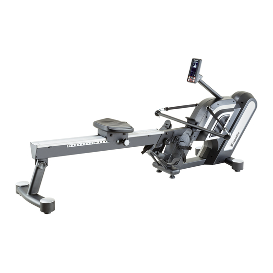
- Page 1 USER MANUAL – EN IN 16443 Rowing Machine inSPORTline Yakapa...
-
Page 2: Table Of Contents
CONTENTS SAFETY INSTRUCTIONS ........................3 PARTS DESCRIPTION ........................... 3 HARDWARE AND TOOLS ........................6 PARTS LIST ............................7 EXPLODED DRAWING ......................... 11 ASSEMBLY STEPS ..........................12 FOLDING ............................... 15 CORRECT ROWING GUIDE ........................ 16 SINGLE SCULL EXERCISE ...................... 19 ROWING EXERCISE ........................ 19 CORRECT ROWING EXERCISE GUIDE ..................... -
Page 3: Safety Instructions
SAFETY INSTRUCTIONS • Follow basic safety instructions and read this manual carefully before first using. Retain it for future reference. • Do warm-up exercises before each workout to avoid muscle injury and exercise reasonably. Never overstretch yourself. • Regularly check all bolts, nuts and components. They should be well tightened. Regularly check it for damage or wearing. - Page 4 Rear stabilizer 1 set A04/C07 Upholstered seat 1 set Guide rail 1 set A06/A19/D02 Upright post computer 1 set A07/A08/C15/C16 Left/right pedal 2 set Plum knob 62 mm 1 Pc Plum knob 75 mm 1 Pc Foot pedal shaft 1 Pc...
- Page 5 Single scull exercise 1 set handle Rowing handle 1 set Kayaking exercise handle 1 set PVC pads 2 Pcs Aluminum end cap 1 set AC adapter 1 Pc...
-
Page 6: Hardware And Tools
HARDWARE AND TOOLS Picture Description Quantity Screw M6x16 mm 1 Pcs Screw M4x8 mm 2 Pcs Screw M8*16 mm 4 Pcs Washer 5/16”*23*2.0T 4 Pcs Hex tool 19 mm 1 Pc Allen key M10 1 Pc Allen key M5 1 Pc Tool 1 Pc Allen key M4... -
Page 7: Parts List
PARTS LIST Description Qty. Main frame Front stabilizer Rear stabilizer Upholstered seat Track Upright post Foot pedal strap position adjustment assembly-R Foot pedal strap position adjustment assembly-L Single scull exercise handle Rowing handle Kayaking exercise handle Pivot arm of console Foot pedal shaft Foot pedal bracket Aluminium end cap-front... - Page 8 Clip hook Nylon nut M10 Bolt M6 C-ring Washer 3/8” Nylon nut M12 Bolt M8 Nylon nut M8 Washer M8 Screw M4 Screw M8 Shaft ø 12 Bolt M12 Bolt M12 Washer M13 Clip hook Nylon nut 5/16” Plum knob Plum knob Screw M4 Screw M6...
- Page 9 Bolt M8 Plum knob C-ring 40 Screw M5 Spacer Bolt M8 Arc washer M8 Bolt M3 Washer 3/8“ Bolt M8 Main cover/L Main cover/R Foot pad Oval end cap 50x100 Adjustable foot pad Transport wheel Upholstered saddle Seat roller Plastic pulley PVC pads Round end cap - left Rubber pads...
- Page 10 Quick key with gyro sensor 1 set Generator cable Control board cable Control board (CB.) Battery Bearing Bearing Bearing Bearing Bearing Ribbon 2 sets Drive strap Aluminium guide rail Kayaking exercise seat locking bracket...
-
Page 11: Exploded Drawing
EXPLODED DRAWING... -
Page 12: Assembly Steps
ASSEMBLY STEPS Front stabilizer installation • Attach the front stabilizer (A02) to the main frame (A01) with 2x bolts (B26) and 2x washers (B09). Rear stabilizer and guide rail installation • Two people are required for this step. • Undo one bolt M12 (B18) and one washer (B19) and one nylon nut M12 (B10) from the rear guide rail (A05). - Page 13 • Attach the Aluminum End cap (A15) to Guide rail (A05) with one screw M6 (B25). • Tighten nuts with the hex tool with Phillips screwdriver that provided. Upright post installation • Lift the upright post (A06) and connect matching connectors then extra slide extra length cables into the opening of the main frame (A01).
- Page 14 Foot pedal strap position adjustment • Find the lock pin (C15) of the foot strap position adjustment assembly (C21) on the pedal. Pull the lock pin and slide the foot strap to the required position. Secure the foot strap position with the spring-loaded pin clipped into the required hole.
-
Page 15: Folding
Different exercise models handle installation • Please secure the hook of the handlebar of different rowing exercise models to the clip hook of the rowing tension strap (Fig. 01-03). FOLDING • Two people are required for folding. • Remove B23 from the front of A01 (Fig. 01). •... -
Page 16: Correct Rowing Guide
Fig. 03 Fig. 04 Fig. 05 Fig. 06 CORRECT ROWING GUIDE FAULT: OVER REACHING: The body stretches too far forward. The shins may be past vertically. The head and shoulders tend to drop towards the feet. The body is in a weak position for the stroke. SOLUTION: The shins are vertical. - Page 17 Fault Solution FAULT: ROWING WITH BENT ARMS: The user starts the stroke by pulling with the arms rather than pushing with the legs. SOLUTION: The user starts the stroke by pushing the legs and bracing the back with the arms fully extended and relaxed.
- Page 18 FAULT: PULLING THE BODY TO THE HANDLE: At the finish, the user, instead of pulling the handle to the body, pulls themselves forward to the handle for the stroke. SOLUTION: At the finish, the user leans back slightly, holds the legs down and draws the handle to the body using the upper body as a firm platform.
-
Page 19: Single Scull Exercise
NOTE: Secure the hook of the handlebar of different rowing exercise models to the clip hook of the rowing tension strap. 1. SINGLE SCULL EXERCISE This new rowing machine can simulate the exercise of the single scull rowing exercise. Fig. 1 2. -
Page 20: Correct Rowing Exercise Guide
CORRECT ROWING EXERCISE GUIDE Three phases of correct rowing exercise for muscle group training: 1. Drive (lower body muscle group training): Bend your knee and stretch your arms. Hold the handle of the rowing machine with back straight up (Fig. 01). 2. -
Page 21: Ac Adapter Installation
AC ADAPTER INSTALLATION • Connect the AC adapter (D03) to the AC plug cable (D11) on the rear of the main frame (A01). • Make sure the specifications of power supply on the adapter is correct before plugging it in. •... -
Page 22: Computer Operation Manual
• Prevent this machine and especially the computer console from direct sunlight. • Inspect all assembly bolts and pedals of the machine every week. Retighten them, if necessary. • Store it in a clean and dry place away from children. COMPUTER OPERATION MANUAL DISPLEJ Values... -
Page 23: Operation
OPERATION POWER ON When the console is connected to the power supply, a beep sounds and all values are displayed for 2 seconds. (Drawing. 1). Once started, the console switches to training mode. The KAYAKING / ROWING / SINGLE modes will be displayed in order (Drawing. - Page 24 A. Use ENTER to select K-5 20/10 interval mode. WORK / REST and CYCLE are displayed for 2 seconds. (Drawing. 11~12). B. Use the UP / DOWN buttons to set the load (Drawing. 13). C. Press ENTER to start the program. Press RESET to stop without SPM. D.
- Page 26 ROWING Press ENTER button in ROWING mode, select mode R-1~R-9, with UP / DOWN. 1. R-1 – Manual mode A. Press ENTER to select R-1 manual mode, use UP / DOWN buttons to set the load. (Drawing. 26). B. Press ENTER to start the program. Press RESET to stop without SPM. 2.
- Page 27 D. Press ENTER to start the program. Press RESET to stop without SPM. E. During exercise, the set training countdown is displayed. (Drawing. 43) F. During exercise, the set rest time is displayed. (Drawing. 44) G. Steps E and F repeats according to settings. 7.
- Page 29 SINGLE REŽIM Press ENTER button in SINGLE mode, choose modes S-1~S-9, with UP / DOWN buttons. 1. S-1 – Manual mode A. Press ENTER to select S-1 manual mode, use UP / DOWN buttons to set the load. (Drawing. 47). B.
- Page 30 D. Press ENTER to start the program. Press RESET to stop without SPM. E. During exercise, the set training countdown is displayed. (Drawing. 61) F. During exercise, the set rest time is displayed. (Drawing. 62) G. Steps E and F repeats according to settings. 8.
- Page 31 POZNÁMKA: • Během cvičení se TIME/500, CALOREIS, STROKE / TIME, WATTS a TOTAL STROKE zobrazují v cyklu každých 5 vteřin. • Konzole se přepne do úsporného režimu po 4 minutách neaktivity. • Pokud konzole nefunguje správně, zkuste vypojit a zapojit adaptér.
-
Page 32: Warm-Up Exercise
WARM-UP EXERCISE Quadriceps Stretch With one hand against a wall for balance. Reach behind you and pull your right foot up. Bring your heel as close to your buttock as possible. Hold for 15 seconds and repeat with your left foot. Inner Thigh Stretch Sit with the soles of your feet together with your knees pointing outwards. - Page 33 otherwise specified in the Purchase Agreement, in the Amendment to this Contract or in another written agreement. Warranty Conditions Warranty Period The Seller provides the Buyer a 24 months Warranty for Goods Quality, unless otherwise specified in the Certificate of Warranty, Invoice, Bill of Delivery or other documents related to the Goods. The legal warranty period provided to the Consumer is not affected.
- Page 34 26847264 VAT ID: CZ26847264 Phone: +420 556 300 970 E-mail: eshop@insportline.cz reklamace@insportline.cz servis@insportline.cz Web: www.inSPORTline.cz inSPORTline s.r.o. Headquaters, warranty & service center: Električná 6471, Trenčín 911 01, SK CRN: 36311723 VAT ID: SK2020177082 Phone: +421(0)326 526 701 E-mail: objednavky@insportline.sk reklamacie@insportline.sk servis@insportline.sk...
Need help?
Do you have a question about the Yakapa and is the answer not in the manual?
Questions and answers