Table of Contents
Advertisement
Quick Links
Advertisement
Table of Contents

Related Manuals for Insportline RowAir


Summary of Contents for Insportline RowAir
- Page 1 USER MANUAL – EN IN 25950 Rowing Machine inSPORTline RowAir...
-
Page 2: Table Of Contents
CONTENTS SAFETY INSTRUCTIONS ........................3 PRODUCT DESCRIPTION ........................4 FASTENERS ............................4 ASSEMBLY ............................. 6 CONTROL PANEL ..........................18 INTRODUCTION ..........................18 FUNCTION............................18 DISPLAY ............................19 PROGRAMS ............................21 BLUETOOTH ............................. 23 RESISTANCE ADJUSTMENT ......................23 PEDAL SIZE ............................24 POSITION OF HANDLES ........................ -
Page 3: Safety Instructions
SevenSport s.r.o. reserves the right to make any changes and improvements to its product without prior notice. Visit our website www.insportline.eu where you will find the latest version of the manual. SAFETY INSTRUCTIONS • Read this manual carefully before first using and retain it for future reference. -
Page 4: Product Description
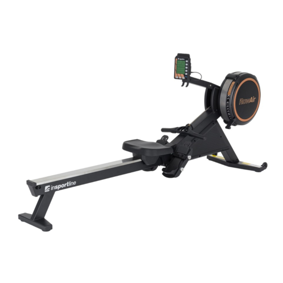
PRODUCT DESCRIPTION End cap Fan cover Rails Resistance indicator Seat Front frame Handle Front stabilizer Handle holder Main frame Console display Cover Mobile phone holder Pedals Console holder Rear stabilizer FASTENERS Name Qty. Allen screw M6x16 mm Phillips screw M6x12 mm Allen screw M8x20 mm... - Page 5 Allen screw M8x75 mm Phillips screw M6x16 mm Screw M8x20 mm Washer M6 Washer M8 Pedal end Stop Nylon nut M8 Screwdriver Allen screwdriver 6 mm Allen screwdriver 5 mm Wrench 13 mm / 15 mm...
-
Page 6: Assembly
ASSEMBLY Step 1 Carefully remove all parts from the box. Be careful not to place the main frame on side, fan shrouds can dent easily if you put the weight of the whole frame on them. Main frame 1 pcs Rail 1 pcs Cover 1 pair Front frame 1 pcs... - Page 7 Cardboard 1 pcs Cardboard 1 pcs Cardboard 1 pcs Cardboard 1 pcs Cardboard 1 pcs Cardboard 1 pcs Polystyrene 1 pcs Step 2 Place the main frame (1) on the carton (A and B). Support the frame (1) with cartons (A and B), place polystyrene (C) between the two cartons for additional support of the frame.
- Page 8 Step 3 Attach the front frame (7), pay attention to the direction of the arrow, it must point outwards, see picture. Attach the front frame (7) to the main frame (1) using 4x M8 flat washers (76) and 4x M6x16 Allen screws (99).
- Page 9 Step 4 Attach the cover (160 and 161) to the main frame (1) see picture. Note: Do not put too much pressure on the covers.
- Page 10 Step 5 Fasten the covers (160 and 161) to the frame (1) and the front frame (7) using 10x Phillips screws (165). First, tighten the 2x screws on the main frame (1). Note: Do not tighten the screws yet.
- Page 11 Step 6 Continue fixing the covers (160 and 161) to the main frame (1) using 8x M6x12 screws (165). Note: Then tighten all screws from steps 5 and 6.
- Page 12 Step 7 Attach the front stabilizer (4) to the front frame (7) using 4x washers (76) and 4x M6x16mm Allen screws (99). Note: Tighten the screws.
- Page 13 Step 8 Lift the structure from the cartons (A and B) and place the structure on the transport wheels and fan frame. Attach the pedals (177) to the main frame (1) using the 16 mm shaft (139) and the 12 mm shaft (140).
- Page 14 Step 9 Lift the frame (1) by grasping the pedal strap (47). Using the other hand, fit the rail (2) into the 12mm shaft (140) on the main frame (1). See picture. Then insert the pin (98) into the main frame (1) and the rail (2).
- Page 15 Step 10 Attach the control panel bracket (135) to the covers (57 and 58) using 2 x M6x12 mm Phillips screws (165). Note: Tighten all screws.
- Page 16 Step 11 Attach the control panel (19) to the bracket (179) using 1x M8x75mm screw (78), 1x M8 flat washer (79) and 1x M8 nut (80). Connect the sensor cable (23) to the console (19a).
- Page 17 Step 12 Slide the saddle (10) onto the rail (2) and then attach the back cover (67) to the rail (2) with 2x M6x16mm screws (83). Fix the stopper (116) to the rail (2) with 1x M8 washer (79) and 1x screw (117). Note: Tighten all screws.
-
Page 18: Control Panel
CONTROL PANEL INTRODUCTION Turn on As soon as you move the handles, the quick start program will start or press any button and the control panel will switch to standby mode. Turn off If the control panel is in standby mode or no activity is recorded for 20 seconds, it turns off. Battery replacement The control panel is powered by 2x D batteries. -
Page 19: Display
During program selection, the button serves as a return to the previous program. During the setting of the values, the button serves as a return to the previous value after confirmation. During the exercise, press the button to stop the exercise. Calorie and watt values are reset to zero. Press the button again to view the exercise summary. - Page 20 Strokes Displays the number of strokes during the exercise. Range: 0 – 9999. Cycle, level Range for cycle: 0 – 35 Only shown in the interval program. Displays the current interval. Range for load: 1 – 16 Displays the resistance level during exercise. Levels 1 – 10 are air resistance. Levels 11 – 16 are magnetic resistance.
-
Page 21: Programs
PROGRAMS • The control panel includes 8 programs: Quick start, Distance Countdown, Time Countdown, Calories Countdown, Time Interval, Distance Interval, Calorie Interval and memory. • By pressing PROG you can switch between the programs in the following order: Quick start, Distance Countdown, Time Countdown, Calories Countdown, Time Interval, Distance Interval, Calorie Interval and memory. - Page 22 • First, you need to set the distance of each training interval. After setting all training intervals, press ENTER to set rest intervals. • Training range: 100 - 5000 meters • Rest range: 00:10 – 30:00 (minutes:seconds) • Number of intervals: 35 Calories interval •...
-
Page 23: Bluetooth
Interval programs Distance countdown Rule Split: Rule Split: 1 cycle = 1 interval Up to 35 500 >= distance > 250 20 km 250 >= distance > 100 10 km 100 >= distance > 50 5 km 50 >= distance > 20 2 km 20 >= distance 1 km... -
Page 24: Pedal Size
Resistance 11 – 16 Always set the indicator so that it is slightly above the desired value on the axis Resistance 1 – 10 Always set the indicator so that it is slightly below the desired value on the axis Note: always make sure that the desired value is displayed on the control panel. -
Page 25: Position Of Handles
POSITION OF HANDLES Handles (3) can be placed on A. console holder (134) or in B. handle holder (52). SMARTPHONE HOLDER You can extend or retract the phone holder (156). Slide the holder up, place the phone between the holder and the control panel, then slide in to hold the phone in place. ADJUSTING THE ANGLE OF THE CONTROL PANEL You can adjust the position of the console holder (134) by holding the console on both sides and moving it to a suitable position. -
Page 26: Maintenance
MAINTENANCE • Regularly check that the resistance of the handles (3) is working. The movement of the seat must be smooth and stable. • Clean the rail (14) regularly with a soft cloth. • Make sure all screws, nuts and connections are properly tightened. Alternatively tighten. •... -
Page 27: Adjusting The Length Of The Bungee Cord
ADJUSTING THE LENGTH OF THE BUNGEE CORD The bungee cord (38) on the handles (3) can wear out over time. 1. Disconnect the rail (2) from the main frame (1). Rest the frame (1) on a firm and elevated point. Remove the covers (160 and 161). Remove the top cover (68) from the main frame (1). Pull the bottom cover (70) out of the main frame. - Page 28 2. Place the frame (1) in the position see picture below. Unhook the left rubber hook (12L) from the main frame (1). Make a mark on the rubber (38) and move the hook approximately 5 cm forward. Unhook the rubber according to points 1-3 below. Move the rubber forward about 5 cm, then hook into the hooks (12L) according to points 4 - 6.
-
Page 29: Storage
STORAGE Store the trainer in a dry and clean place. If you are storing the trainer for an extended period of time, remove the batteries. Move the trainer on the transport wheels (66) on the front stabilizer (4). Lift the trainer by the rear stabilizer (2). -
Page 30: Drawing
DRAWING... -
Page 31: Parts List
PARTS LIST Name Qty. Main Frame Rail Frame Handlebar Front Stabilizer Front Support Leg Seat Carriage Bungee Cord Hook Chain Bracket Stainless Steel Rail Perforated Steel Mesh Spacer, 8.2x 12x3.2mm Spacer, 8.2x 12x71.6mm Spacer, 6.2x 10x15.5mm Console Monitor Generator Sensor Cable Shaft, M6x 12x80mm Shaft, M6x 10x76.5mm Fan Axle... - Page 32 Damper Left Fan Shroud Right Fan Shroud Foot Pedal Foot Pedal Holder Pedal Strap Spacer, 10x 16x30.5mm Pulley Spacer, 10x 16x26.5mm Pulley Bushing Seat Handlebar Holder Upper Joint Cover Lower Joint Cover Generator Base Left Side Cover Right Side Cover Foot Cap Steel Plate Bushing 6001...
- Page 33 Phillips Flat Head Screw, M6x16mm Socket Head Cap Screw, M8x110mm Button Head Cap Screw, M8x25mm Lock Washer, M8 Phillips Head Screw, ST4.2x16mm Phillips Flat Head Screw, M5x12mm Socket Head Cap Screw, M5x92mm Hex Nut, M5 Chain Hook Elastic Ring Nylon Lock Nut, M10 Phillips Head Screw, ST4.2x6mm Phillips Head Screw, M4x45mm Hex Nut, M4...
- Page 34 Lock Washer, M6 Phillips Pan Head Self-drilling Screw, ST4.2X19mm Allen Wrench, 5mm Upper Console Monitor Post Lower Console Monitor Post Screw Shaft Small Pulley Bushing Rotation Sleeve Pedal Shaft, 16mm Pedal Shaft, 12mm Pin, M6x77mm Post, M6x63mm Magnet Bracket Stainless Steel Spacer, Φ10xΦ6x25mm Aluminum Plate VR Holder Ring...
-
Page 35: Warm Up
Hex Head Cap Screw, M6x20mm Hex Head Cap Screw, M6x40mm Phillips Head Screw, M6x16mm Phillips Flat Head Self-Tapping Screw, ST4.2x16mm Socket Head Cap Screw, M8X20mm Seat Carriage Cover Pedal Support Plate Foot Pedal End Cap Console Mounting Bracket WARM UP Regular exercise begins with warming up and ends with rest exercises. - Page 36 Cooling-Down Phase This stage is to let your cardio-vascular system and muscles wind down. This is a repeat of the warm- up phase. First, reduce your tempo and continue at this slower pace for approximately 5 minutes before you get off your Exercise Bike. The stretching exercises should now be repeated, again remembering not to force or jerk your muscles into the stretch.
-
Page 37: How To Exercise
Training Time Rowing is a strenuous form of exercise, because of this it is best to start with a short, easy exercise programmed and build up to longer and harder workouts. Start rowing for about 5 minutes and as you progress, increase the length of your work out to match your improving level of fitness. -
Page 38: Important Notice
IMPORTANT NOTICE • This rowing machine comes with standard safety regulations and is suitable for commercial use. We are not responsible for any injury caused by improper and forbidden use of the machine. • Consult your doctor before starting training on the rowing machine. Your doctor should evaluate whether you are physically fit to use the machine and how much effort you are able to undergo. - Page 39 “The Buyer who is the End Customer” or simply the “End Customer” is the legal entity that does not conclude and execute the Contract in order to run or promote his own trade or business activities. “The Buyer who is not the End Customer” is a Businessman that buys Goods or uses services for the purpose of using the Goods or services for his own business activities.
- Page 40 VAT ID: CZ26847264 About shipping Phone: +420 556 300 970 E-mail: eshop@insportline.cz reklamace@insportline.cz servis@insportline.cz Web: www.inSPORTline.cz inSPORTline s.r.o. Headquaters, warranty & service center: Električná 6471, Trenčín 911 01, SK CRN: 36311723 VAT ID: SK2020177082 Phone: +421(0)326 526 701 E-mail: objednavky@insportline.sk reklamacie@insportline.sk...
Need help?
Do you have a question about the RowAir and is the answer not in the manual?
Questions and answers