Table of Contents
Advertisement
Quick Links
Advertisement
Table of Contents

Related Manuals for Insportline Yukona


Summary of Contents for Insportline Yukona
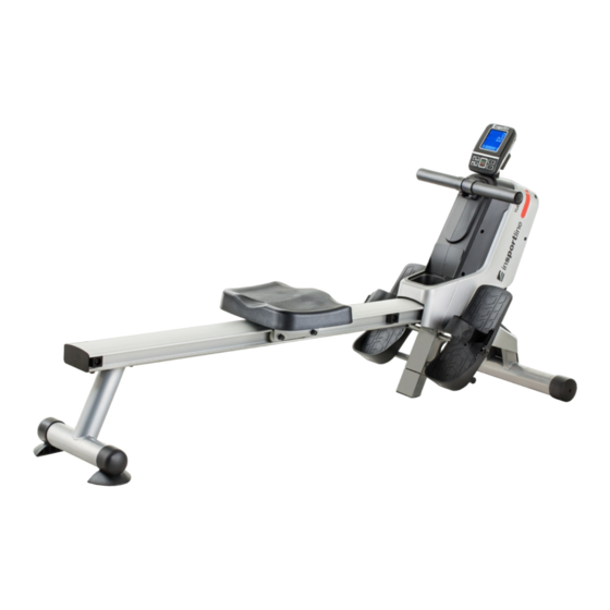
- Page 1 USER MANUAL – EN IN 16635 Rowing Machine inSPORTline Yukona SevenSport s.r.o. reserves the right to make any changes and improvements to its product without prior notice. Visit our website www.insportline.eu where you will find the latest version of the manual.
-
Page 2: Table Of Contents
CONTENTS PRODUCT DESCRIPTION ........................4 ASSEMBLY PARTS ..........................5 ASSEMBLY STEPS ..........................6 STORAGE ............................... 9 MOVING INSTRUCTIONS ........................10 EXPLODED DRAWING ......................... 11 PARTS LIST ............................12 CONSOLE ............................. 15 PROGRAMS ............................16 CHEST BELT USE ..........................19 HOW TO EXERCISE ..........................19 MAINTENANCE ............................ - Page 3 SAFETY PRECAUTIONS • Read this manual carefully before first using and retain it for future reference. • Observe all warnings and precautions including assembly steps. Use it only for intended purpose. • Assemble and use it only according to this manual to assure your safety. Inform all other users about safe usage.
-
Page 4: Product Description
PRODUCT DESCRIPTION 1) Handlebar 2) Left cover 3) Bottle holder 4) Pedal strap 5) Seat 6) Rail 7) Rear stand 8) End cap 9) Meter 10) Right cover 11) Front cover 12) Transporting wheels 13) Front stand 14) Pedal... -
Page 5: Assembly Parts
ASSEMBLY PARTS Picture Description Qty. Button head bolt M8x40 mm Button head bolt M8x15 mm Button head bolt M8x20 mm Flat washer M8 Large washer M8 Flat washer M6 Lock washer M8 Cross self-tapping bolt ST4.2x45 Cross flat head bolt M6x15 Allen wrench 5 mm Screwdriver and wrench Bolt M5x20... -
Page 6: Assembly Steps
ASSEMBLY STEPS STEP 1 • Position the rowing machine as shown in picture A. • Insert the rear support (5) into the base frame (3) and lock with button head bolts M6x15 mm (63) and washers M6 (64). • Attach the base frame (3) to the connection bracket (11) with button head bolts M8x40 mm (84) and washers M8 (62). - Page 7 STEP 4 • Attach the seat (21) to the seat carriage (10) with round head bolts M6x15 mm (63) and washers M6 (64). STEP 5 Connect the bracket sensor cable (35a/35b) to the cables leading from the cover (95a/95b) and screw the bracket (35) to the rear bracket cover (36) with bolts M5x20 (57).
- Page 8 NOTE: Lubricate the handlebar (15) with a small amount of liquid soap or water for easier installation of the foam grip (22). STEP 7 • Put the end cap (30) into the rear stand (2). STEP 8 • Lock the front cover (28) onto the base frame (3) with round head screw ST4.2x45 (81). STEP 9 •...
-
Page 9: Storage
STORAGE • Store it only in a clean and dry place. • Move this device using moving wheels on the front stabilizer of the base frame (3). Lift the rear stand (2) to move it. Never use seat (21) to push or pull it. The seat could move, the seat carriage (10) could hurt or crush your fingers. -
Page 10: Moving Instructions
MOVING INSTRUCTIONS • Rise up the rear stabilizer and push the rower machine to move it. -
Page 11: Exploded Drawing
EXPLODED DRAWING... -
Page 12: Parts List
PARTS LIST Item Qty. Main frame Rear stand Base frame Foot bracket Rear support Pedal shaft Rear spring hook Spring hook Rail cap Seat carriage Connection bracket Magnetic bracket Spacer (ø12.8.x38.5 mm) Shaft rod (ø12.8.x58.5 mm Handlebar Round head self-drill (ST4.2x20 mm) Left cover Right cover Pedal cap... - Page 13 Meter plate Foot stand PU roller Return bearing housing Strap pulley shaft ø10*100 Strap pulley Bearing (6000RS) Bearing (6003zz) Pulley ø155*J3 Round-head bolt (M6x25 mm) One-way bearing (16003) Collar Rail Magnetic flywheel Flywheel shaft V-ribbed belt (220 PJ3) Idler roller Idler wheel Button head bolt M8x20 Bearing (608zz)
- Page 14 Inner C ring M35 Spacer Retaining plug Eye bolt M6 Tension bracket Nut M10 Nut M6 Round-head screw ST4.2x45 Cross head screw M5x12 Large washer M8 Button head bolt M8x40 Button head bolt M8x20 Round-head screw M6x12 Button head bolt M8x60 Button head bolt M8x80 Spacer S10 Thin nut M10...
-
Page 15: Console
CONSOLE DISPLAY FUNCTION DESCRIPTION RANGE 0:00 – 99:59 min:sec TIME Exercise time 0:00 – 99:59 min:sec TIME/500 m Time to reach 500 m 0 – 99999 m Distance 10 – 990 WATT Power 30 – 240 PULSE Current heart rate 0 –... -
Page 16: Programs
RESISTANCE GRAPH DISPLAY 1. COUNT: Number of pulls 2. PROGRAM: Program type 3. TIME: Current exercise time 4. 12 -24: Load, current (12), next (24) PROGRAMS MANUAL (P01) Press S.T / STP to start or press RECOVERY SET RST to enter setting. Use the RECOVERY SET RST button to select a function, the selected value will flash (time, distance, strokes, calories) Use the UP and DOWN buttons to set the value, press RECOVERY SET RST to move to the next... - Page 17 Use the RECOVERY SET RST button to select a function, the selected value will flash (time, distance, strokes, calories) Use the UP and DOWN buttons to set the value, press RECOVERY SET RST to move to the next value. After setting all the values, the program will start automatically, or you can press the ST./STP button to start the program.
- Page 18 If time, distance, calories, pull-ups are set, they will be displayed as a countdown. When 0 is reached, an audible signal sounds and the program is switched off. Press ST / STP to stop the program. Note: The program can only be started if the heart rate is detected. BODY FAT (P14) Use the RECOVERY SET RST button to select a function, the given value will flash (gender M-male / F-female, weight, height, age).
-
Page 19: Chest Belt Use
RECOVERY If the console detects a heart rate, hold the RECOVERY SET RST button for 3 seconds. A countdown of 0:60 will be displayed. When the calculation is complete, the result F1 (best) - F6 (worst) will be displayed. After completing the test, press RECOVERY SET RST to return. ERROR CODES The recovery test did not Check that the chest strap is... -
Page 20: Maintenance
6. Practice of back and abdominal muscles (Pic 06) MAINTENANCE • Cleaning: Use a soft cloth and gentle cleaner to clean the product. • Do not use abrasives or solvents on plastic parts. • Wipe the sweat after each use. •... - Page 21 “The Buyer who is not the End Customer” is a Businessman that buys Goods or uses services for the purpose of using the Goods or services for his own business activities. The Buyer conforms to the General Purchase Agreement and business conditions. These Conditions of Warranty and Warranty Claims are an integral part of every Purchase Agreement made between the Seller and the Buyer.
- Page 22 Seller is obliged to provide the Buyer with a financial compensation in the form of a refund. SEVEN SPORT s.r.o. inSPORTline s.r.o. Strakonická 1151/2c, Praha 5, 150 00, ČR Headquaters, warranty & service center: Električná 6471, Registered Office: Dělnická...
Need help?
Do you have a question about the Yukona and is the answer not in the manual?
Questions and answers