Advertisement
Advertisement

Subscribe to Our Youtube Channel
Related Manuals for Insportline RW60


Summary of Contents for Insportline RW60
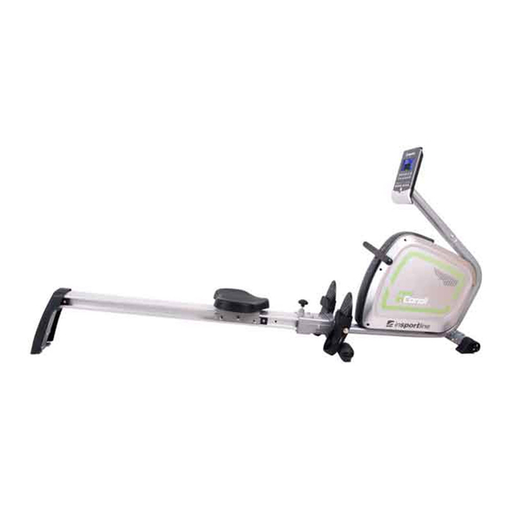
- Page 1 USER MANUAL – EN IN 8722 Rowing Machine inSPORTline RW60...
-
Page 2: Table Of Contents
CONTENTS EXPLODED VIEW ..............................3 PARTS LIST ................................3 ASSEMBLY ................................6 INSTRUCTION MANUAL OF SM5810-64 ......................10 TERMS AND CONDITIONS OF WARRANTY, WARRANTY CLAIMS ............13... -
Page 3: Exploded View
EXPLODED VIEW 35 27 50 29 39 50 27 78 84 PARTS LIST Q’TY DESCRIPTION Computer Handlebar post Stabilizer Pulling rope D5*2000L Foam roller Half ball cap Foam D23x4Tx400L Pedal Ankle strap Rear cover Rear supporting plate Bushing D10.5*D7.5*9T Axle Ball knob Welding set for sliding beam Sliding beam... - Page 4 Fixing plate Fixing plate for sensor Main frame Screw ST4.2*15L Seat Seat support Pulley Nut D9.5x5T (3/8"-26UNF) Lower computer cable Sensor(1) Lower computer cable Tension cable Sensor Motor Wheel for pulling rope Anti-loosen nut 3/8"-26UNFx6.5T Bushing D13.5*D10*9 Pulley Upper computer cable Lower computer cable(2) Round magnet Plastic washer D10*D24*0.4T...
- Page 5 Volute spring 20*0.7T Nylon nut M8*1.25*8T Bushing D12*D8.2*12.6L Buffer D11*7L Fixing plate for spring Buffer D24*D8*22 Fixing bracket for volute spring Flywheel axle Bearing #6000ZZ Electric cable Screw ST4x1.41x10L Screw M5*0.8*10L Flat washer D21*D8.5*1.5T Pulley Enforcing plate Bolt M8*25 Screw M6*1.0*20L Ladder screw M8*1.25*55.5L Spring washer D15.4*D8.2*2T Domed nut M8*1.25*15L...
-
Page 6: Assembly
Buffer Fixing board Nut M8*P1.25*6T Chest belt Adaptor Front stabilizer ASSEMBLY STEP 1 step-1 M8*75 D15.4 D22 M8*1.25 A. Assemble the rear stabilizer (5) to the main frame (22) by using spring washer (74), domed nut (75), curved washer (80) and square neck bolt (90). B. - Page 7 STEP 2 & 78 84 61&96 72 step-2 M8*1.25*100 M8*20 D15.4 M6*20 D10.5 D13 M10*1.5*150 A. Assemble the rear supporting plate (13) with sliding beam (19) by fixing plate (95), spring washer (74) and allen bolt (87) as picture 1 shown. B.
- Page 8 STEP 3 A x2 step-3 M8*20 Assemble the foot pedal (10) using the axle (16), flat washer (77) and bolt (91).
- Page 9 STEP 4 A x2 step-4 M5*10 M8*20 D15.4 D22 A. Connect the upper computer cable (38A) and lower computer cable (38B) and then assemble the handlebar post (2) onto the main frame by spring washer (74), curved washer (80) and allen bolt (87) as the picture A shown.
-
Page 10: Instruction Manual Of Sm5810-64
INSTRUCTION MANUAL OF SM5810-64 DISPLAY FUNCTIONS ITEM DESCRIPTION Stoke per minute Display range 0~999 Workout time display during rowing. Display range 0:00~99:59 Time/500m Scan every 6 seconds, Computer will display the time needed to row 500 meters according to current speed. - Page 11 Display range 0-30~240. Room temperature display during power saving mode. Temperature YY/MM/DD display during power saving mode. Calendar Clock display during power saving mode. Clock Manual mode workout. MANUAL 12 PROGRAM selection. PROGRAM Target HR training mode. (Preset User age before training) H.R.C ...
- Page 12 PROGRAMS MANUAL MODE 1. Press START key in main menu may start workout in manual mode. 2. Press UP or DOWN to select Manual mode and press ENTER to confirm. 3. Press UP or DOWN to preset LEVEL, TIME, STROKES, CALORIES, WATT and PULSE, and press ENTER to confirm.
-
Page 13: Terms And Conditions Of Warranty, Warranty Claims
USER MODE 1. Press UP or DOWN to select USER mode and press ENTER to confirm. 2. Press UP or DOWN to set resistance level of each column, and press ENTER to next one. (Total column = 16) 3. Hold on pressing MODE to finish or quit setting 4. - Page 14 These Conditions of Warranty and Warranty Claims are an integral part of every Purchase Agreement made between the Seller and the Buyer. All Warranty Conditions are valid and binding, unless otherwise specified in the Purchase Agreement, in the Amendment to this Contract or in another written agreement. Warranty Conditions Warranty Period The Seller provides the Buyer a 24 months Warranty for Goods Quality, unless otherwise specified in the...
- Page 15 +420 556 770 190, Mobile: +420 604 853 019, servis@insportline.cz Fax: +420 556 770 192, (Service +420 556 770 191) Web: www.insportline.cz, www.worker.cz, www.worker-moto.cz INSPORTLINE, s.r.o. Bratislavska 36, 911 05 Trencin, Slovakia CRN: 36311723, VAT ID: SK2020177082 Orders: +421(0)326 526 701, +421(0)917 649 192, objednavky@insportline.sk...
Need help?
Do you have a question about the RW60 and is the answer not in the manual?
Questions and answers