Advertisement
Quick Links
Advertisement

Related Manuals for Insportline ProfiGym C95


Summary of Contents for Insportline ProfiGym C95
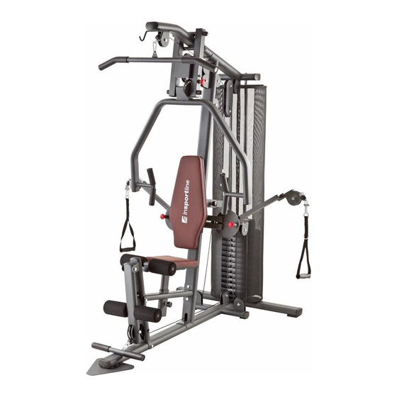
- Page 1 USER MANUAL – EN IN 9306 Home Gym inSPORTline ProfiGym C95...
- Page 2 CONTENTS PARTS LIST ................................3 EXPLODED-VIEW ..............................5 ASSEMBLY INSTRUCTIONS ..........................6 TERMS AND CONDITIONS OF WARRANTY, WARRANTY CLAIMS ............20...
- Page 3 PARTS LIST...
- Page 5 EXPLODED-VIEW...
-
Page 6: Assembly Instructions
ASSEMBLY INSTRUCTIONS STEP 1 1. Attach the Base Frame (5) to the Back Base Frame (11), using two M10X120mm Hex Bolts (78), four M10 Arc Washers (95) and two M10 Nylon Nuts (97). 2. Remove two M10X20mm Hex Bolts (84) and two M10 Washers (93) from two Weight Guide Tubes (13). - Page 7 STEP 2 1. Slide twelve Weight Plates (31) down two Weight Guide Tubes (13). 2. Slide the Selector Shaft Bushing (102) down the Selector Shaft (14) at first hole fix with the Selector Shaft Pin (103). 3. Insert the Selector Shaft (14) into hole of the Weight Plate (31). 4.
- Page 8 STEP 3 1. Attach the Main Frame (6) to the Base Frame (5), using two M10X65mm Carriage Bolts (99), two M10 Washers (93) and two M10 Nylon Nuts (97). 2. Slide the Upper Fixed Tube (15) onto two Weight Guide Tubes (13), using two M8X15mm Hex Bolts (88).
- Page 9 STEP 4 1. Attach the Seat Support Frame (3) to the Main Frame (6), using two M10X70mm Hex Bolts (81), four M10 Washers (93) and two M10 Nylon Nuts (97). 2. Attach the Front Upright Frame (2) to the Base Frame (5) and the Seat Support Frame (3), using one M10X120mm Hex Bolt (78), one M10X100mm Hex Bolt (80), four M10 Washers (93) and two M10 Nylon Nuts (97).
- Page 10 STEP 5 1. Attach the Leg Extension Frame (1) to the Front Upright Frame (2), using one M10X105mm Hex Bolt (79), two M10 Washers (93) and one M10 Nylon Nut (97). 2. Attach the Left Connect Frame (18) and the Right Connect Frame (20) to the Upper Cross Beam (16), using six Oil Bushings (small) (52), one Shaft (M16) (47), two M16 Washers (92), two M16 Nylon Nuts (96) and two Plastic Dome Caps (58).
- Page 11 STEP 6 1. Attach the Backrest Cushion (29) to the Backrest Frame (7), using two M8X40mm Hex Bolts (86) and two M8 Washers (94). 2. Attach the Backrest Frame (7) to the Main Frame (6), using one Knob (44). 3. Attach the Seat Cushion (28) to the Seat Frame (4), using two M8X45mm Hex Bolts (85) and two M8 Washers (94).
- Page 12 STEP 7...
- Page 14 1. Start with the Upper Cable (39): a) With Upper Cable (39) in groove of Pulley (56) through Upper Cross Beam (16). b) Install Pulley NO.1 (56) to Upper Cross Beam (16), using one M10X40mm Hex Bolt (82), two M10 Washers (93) and one M10 Nylon Nut (97). c) Install Pulley NO.2 (56) to Main Frame (6), using one M10X40mm Hex Bolt (82), two M10 Washers (93) and one M10 Nylon Nut (97).
- Page 16 2. Assembly the Lower Cable (38): a) With Lower Cable (38) in groove of Pulley (56) through Leg Extension Frame (1). b) Install Pulley NO.10 (56) and two Pulley Bushings (61) to Leg Extension Frame (1), using one M10X100mm Hex Bolt (80), two M10 Washers (93) and one M10 Nylon Nut (97). c) Install Pulley NO.11 (56) and two Pulley Bushings (61) to Front Upright Frame (2), using one M10X100mm Hex Bolt (80), two M10 Washers (93) and one M10 Nylon Nut (97).
- Page 18 3. Assembly the Arm Cable (37): a) Run Arm Cable (37a) through Arm Fixing U (10). b) Install two Pulleys NO.14&22 (55) to Arm Fixing U (10), using two M10X40mm Hex Bolts (82), four M10 Washers (93) and two M10 Nylon Nuts (97). c) Run Arm Cable (37a) under the bolt pre-assembled on Arm Fixing U (10), through Ball (37b), and wedge the ball end of Cable (37a) to Cable U (50).
- Page 19 STEP 8 1. Insert the U-type Shaft (24) into the both up and down ends of the Safety Cover (32). 2. Attach the Safety Cover (32) to the Lower Fixed Tube (12) and the Upper Fixed Tube (15), and raise the Upper Fixed Tube (15) to tighten the Safety Cover (32), and then M8X15mm Hex Bolts (88) to fix the Upper Fixed Tube (15) on the Weight Guide Tube (13).
- Page 20 TERMS AND CONDITIONS OF WARRANTY, WARRANTY CLAIMS General Conditions of Warranty and Definition of Terms All Warranty Conditions stated hereunder determine Warranty Coverage and Warranty Claim Procedure. Conditions of Warranty and Warranty Claims are governed by Act No. 40/1964 Coll. Civil Code, Act No. 513/1991 Coll., Commercial Code, and Act No.
- Page 21 +420 556 770 190, Mobile: +420 604 853 019, servis@insportline.cz Fax: +420 556 770 192, (Service +420 556 770 191) Web: www.insportline.cz, www.worker.cz, www.worker-moto.cz INSPORTLINE, s.r.o. Bratislavska 36, 911 05 Trencin, Slovakia CRN: 36311723, VAT ID: SK2020177082 Orders: +421(0)326 526 701, +421(0)917 649 192, objednavky@insportline.sk...
Need help?
Do you have a question about the ProfiGym C95 and is the answer not in the manual?
Questions and answers