
Related Manuals for Vega FiberFlex LFXG-H


Summary of Contents for Vega FiberFlex LFXG-H
- Page 1 Operating Instructions LFXG-H ® FiberFlex Detector with GEN2000 ® ® Electronics for Level Measurement Document ID: 31386 Nuclear...
- Page 3 The material in this document is provided for informational purposes and is subject to change without notice. GEN2000® is a registered trademark of the VEGA Americas, Inc. VEGA View and Ohmview 2000 are trademarks of VEGA Americas, Inc. HART® is a registered trademark of The HART® Communication Foundation.
- Page 4 NOTES LFXG-H Installation and Operation Guide...
-
Page 5: Table Of Contents
Tables Explanation of symbols ..................xi LFXG-H specifications ..................17 Contact information ..................26 Conduit Torque Specifications ................. 34 GEN2000 Adapter and Plugs ................34 Calibration methods ..................44 Standard calibration sensor counts and levels record ........51 Process Chain tab — display values ..............60 Process Variables tab —... - Page 6 LFXG-H Installation and Operation Guide...
- Page 7 Table of Contents Revision History ..................i Chapter i Preface ............. ix Explanation of symbols ................ix Your comments ................... x Chapter 1 Introduction ........... 13 Nuclear materials notice ................13 Unpacking the equipment ................. 14 Storing the equipment ................15 Source holder ..................
- Page 8 Switch for CE compliance ..............37 Output current loop ................37 Relay ....................... 37 RS-485 ....................38 Communication ...................38 Process alarm override switch ............38 Conduit ....................39 Commissioning the gauge ................39 Field service commissioning call checklist .........40 Chapter 3 Calibration ............. 41 Calibrating the current loop (analog output) ..........41 Measuring the current loop output ............42 Calibration methods ..................44 Theory of calibration ................44...
- Page 9 When new hardware is installed ..............66 When new hardware is not installed ............66 Test modes ....................67 Test ....................68 Current Loop Test (milliamp output) ........... 68 Sensor Test ..................69 Auxiliary Input Test ................69 Relay Test ..................70 Temperature Test ................
- Page 10 Replacing the CPU or Power supply board ........91 Returning equipment for repair to VEGA ..........94 viii LFXG-H Installation and Operation Guide...
-
Page 11: Chapter I Preface
Preface REFACE Chapter 0 Explanation of symbols In the manual Radiation notice Introduces information concerning radioactive materials or radiation safety. Caution Introduces warnings concerning potential damage to the equipment or bodily harm. On the instrument AC current or voltage A terminal to which or from which an alternating (sine wave) current or voltage may be applied or supplied. -
Page 12: Your Comments
Preface Your comments Manual: LFXG-H Installation and Operation Guide Date: ______________ Customer Order Number: ___________________ Your contact information (optional): Name: ________________________________________ Title: ________________________________________ Company: ________________________________________ Address: ________________________________________ ________________________________________ Did you find errors in this manual? If so, specify the error and page number. ____________________________________________________________ ____________________________________________________________ ____________________________________________________________... - Page 13 Was information you needed or would find helpful not in this manual? Please specify. ____________________________________________________________ ____________________________________________________________ ____________________________________________________________ _________________________ Please send your comments to: VEGA Americas, Inc. Director of Engineering 4241 Allendorf Drive Cincinnati, OH 45209-1599 USA Fax: +1 513-272-0133 LFXG-H Installation and Operation Guide...
- Page 14 Preface LFXG-H Installation and Operation Guide...
-
Page 15: Chapter 1 Introduction
• Relocate • Repair • Test VEGA Field Service engineers have the specific license to install and commission nuclear gauges, and can instruct you to safely operate your level gauge. See page 26 for contact information. Note: See the Radiation Safety for U.S. General and Specific... -
Page 16: Unpacking The Equipment
If there was damage to the unit during shipment, file a claim against the carrier, reporting the damage in detail. Any claim on the VEGA for shortages, errors in shipment, etc., must be made within 30 days of receipt of the shipment. -
Page 17: Storing The Equipment
Introduction Storing the equipment Source holder If you must store it, do so in a clean, dry area. Be sure its shutter is in the OFF or CLOSED position (if applicable). Check the current local regulations (U.S. NRC, Agreement State, or other) to determine whether this area must have any restrictions. -
Page 18: Safety Information For Ex Areas
Introduction Safety Information for EX Areas Please note the EX-specific safety information for installation and operation in EX areas. IECex Label LFXG-H Installation and Operation Guide... - Page 19 Introduction LFXG-H specifications LFXG-H specifications Table 1.1 System ±1% of span Accuracy depends on specific application Accuracy typical parameters Active Lengths Flexible detector 305 – 7,010 mm (12 – 276") in 305 mm (12") increments Typical Cesium-137 0.66 MeV gamma radiation emitter, 30.2 Sources year half life Cobalt-60...
- Page 20 Introduction LFXG-H specifications (continued) Table 1.1 ® GEN2000 4-wire hookup 1.02 – 0.643 mm (no. 18 or 20 AWG) 4- Electronics with DC conductor shielded Housing Certification to • Designed to meet National Electric Code CSA and UL (U.S. and Canada) standards •...
-
Page 21: Typical Applications
Active, Auxiliary, High Voltage, Relay and Field Strength Typical applications VEGA’s level gauges accurately indicate the level of liquids or bulk materials in vessels, reactors, or tanks. In order to achieve a level indication over the desired length, it may be necessary to use more than one detector. -
Page 22: Principle Of Operation
Introduction Pulp and Paper • Liquors • Bleach plant chemicals • Coating chemical storage • Lime mud • Wastewater treatment tanks Chemical • Low pressure/low vapor chemical storage • Settlers • Surge tanks Food and beverage • Food slurries • Pastes •... -
Page 23: System Overview
4 ... 20 mA HART® protocol, frequency, or field bus output. The level measurement system includes: • Source holder • FiberFlex flexible detector assembly • Communication device (HART modem with PC and VEGA software or Emerson Field Communicator 375) System Overview Source holder •... -
Page 24: Detector Assembly
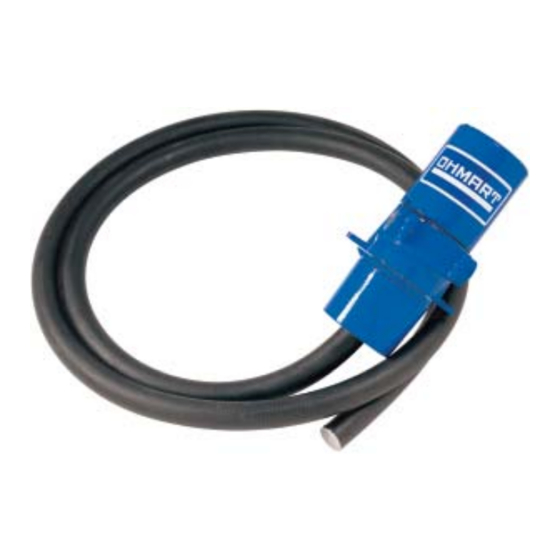
Introduction • Its shutter completely shields the radiation (source off) or lets it pass through the process (source on) (if applicable) Detector assembly • Mounts opposite the source holder. • Inside the flexible detector is a scintillator material, which produces light in proportion to the intensity of its exposure to radiation. -
Page 25: Communicating With The Gauge
Introduction Terminal Block Power supply board RS-485 ground (if applicable) Internal housing ground screw CPU board Mounting Bracket GEN2000 Communicating with the gauge The gauge is a transmitter that produces the current loop signal directly at the measurement site. Use a field communicator or HART modem and Ohmview 2000 software with a PC to enable: •... -
Page 26: Using A Field Communicator
• Key usage • Data entry • Equipment interface To effectively use the gauge features, you must use VEGA's device description (DD) to program the HART communicator. You can purchase a field communicator, programmed with the DD, through VEGA (VEGA part number 244880). - Page 27 Introduction • Stores and retrieves configuration data to disk • Enables offline editing of configurations Example of Ohmview 2000 Software The Ohmview 2000 Software includes: • Main Ohmview 2000 software • HART Communication Server • Launcher program • Ohmview 2000 Logger •...
-
Page 28: Customer Service
Field service engineers also provide assistance by phone during office hours. For emergencies (example: line shut down because of VEGA equipment), you can reach us 24 hours a day. Contact information Table 1.2... -
Page 29: Chapter 2 Installation
To ensure a quick start up after installation, you can test the detector assembly with the HART compatible communication device (a field communicator or a PC with a HART modem and VEGA software). Bench testing lets you check: • Power •... - Page 30 RS-232 cable Transmitter test points PC running VEGA software Bench test setup Note: You may need to reset the time and date if the gauge has not had power for > 28 days. The Real Time Clock Fail message may appear. You must enter the correct time and date: the clock is the basis for source decay calculations.
-
Page 31: Location Considerations
Installation Location considerations When you ordered the gauge, VEGA sized the source for optimal performance. Notify VEGA before installing the gauge if its location differs. Satisfactory operation depends on proper location. Note: Locate the source holder where process material cannot coat it. -
Page 32: Avoid External Obstructions
Installation If the vessel has a central agitator, the source holder and detector can mount to the vessel on an arc other than a diameter, so the beam of radiation does not cross the agitator. You can avoid other obstructions this way. -
Page 33: Mounting The Measuring Assembly
Installation Mounting the measuring assembly Mounting options: • Bracket mount The L-bracket supports the electronics housing. For this type of mounting, the conduit clamps should be spaced every 18" (45cm). • Conduit mount This type of mount consists of an adapter with a 2" conduit coupler (part number 240721). - Page 34 Installation FiberFlex mounting LFXG-H Installation and Operation Guide...
-
Page 35: Wiring The Equipment
Installation Wiring the equipment Remove and Replace Red Threaded Plug The instrument is shipped with red plastic plugs installed in both threaded cable entries. These plugs must be removed during installation and the openings closed by a method approved for flame path protection. Approved and suitable cable glands or blind plugs must be installed. -
Page 36: Conduit Torque Specifications
NPT to M20 x 1.5 316SS Wiring Note: If you received an interconnect drawing from VEGA or the engineering contractor and the instructions differ from the instructions in this manual, use the drawing. It may contain special instructions specific to your order. - Page 37 Installation VEGA provides an internal and external ground screw to connect the power Earth ground wire. Remove the top cover; the internal ground screw is located at the front of the housing. The external ground screw is located next to the conduit entry.
-
Page 38: Power
Installation AC or DC power input Relay: RY NO - normally open RY C - common - normally closed RY NC Not used in HART applications Auxiliary input power Common Auxiliary input frequency signal Current loop output Interconnecting terminals — GEN2000 with HART Note: Not all connections are required for operation. -
Page 39: Switch For Ce Compliance
HART communication protocol (BEL202 FSK standard) is available on these connections. The output is isolated to standard ISA 50.1 Type 4 Class When using signal (current loop or 4 ... 20 mA output) cables that VEGA did not supply, they must meet these specifications: •... -
Page 40: Communication
Installation RS-485 The maximum cable length is 609 meters (2,000'). Use shielded wire per local code. Connect positive terminals together. Connect negative terminals together. Connect ground terminals together. Example GEN2000 level gauge wiring Communication The HART hand-held terminal can connect anywhere across the 4 ... 20 mA wires to communicate with the gauge. -
Page 41: Conduit
Installation Conduit Conduit runs must be continuous and you must provide protection to prevent conduit moisture condensation from dripping into any housings or junction boxes. Use sealant in the conduit, or arrange the runs so they are below the entries to the housings and use weep holes where permitted. You must use a conduit seal-off near the housing when located in a hazardous area. -
Page 42: Field Service Commissioning Call Checklist
10% increments in between for the linearization procedure. Do not remove the lock or shield on the source holder. Notify VEGA Field Service if there is damage to the source holder. LFXG-H Installation and Operation Guide... -
Page 43: Chapter 3 Calibration
Calibrating the current loop adjusts the 4 ... 20 mA output to a reference, the PLC/DCS or a certified ammeter. It forces the 4 mA and 20 mA outputs to the external reference. The VEGA factory pre-adjusts the current loop with a certified ammeter, so it is very close to the outputs required. -
Page 44: Measuring The Current Loop Output
Calibration To correlate the 4 ... 20 mA to the process value, set the span of the current loop output. Note: The current loop and process spans are independent and set separately. The current loop span sets the level indications for the 4 mA and the 20 mA outputs. - Page 45 Calibration Procedure 3.1: To calibrate the current loop 1. Select Calibration | Current Loop Cal. 2. Click Execute. 3. Click OK. 4. Read the ammeter; enter the actual milliamp reading. Note: If using a voltmeter, calculate the current value. 5. Click OK. 6.
-
Page 46: Calibration Methods
Calibration You can check the current loop output calibration at any time by using the test mode to output a user-specified milliamp setting. See 68. Calibration methods For each installation, you must choose a method to calibrate the gauge. In almost all cases, the standard method is the best. -
Page 47: Standard Calibration Method
Calibration The figure illustrates the effect on the final output of using the non-linear table vs. the linear table for the linearizer. Using the non-linear table linearizer in the standard method produces a linear output. Maximum Level Standard Indicated Level Simple Minimum Level... - Page 48 Calibration The internal software calculates a linearizer curve based on data points. The curve is the most accurate between the Cal Low Level and Cal High Level. Cal Low Counts Standard Raw Sensor Counts Simple Cal High Counts Min Level Max Level Cal High Level Cal Low Level...
-
Page 49: Simple Calibration Method
Calibration The linearizer curve maps on 2 axes so it indicates % Count Range vs. % Span. 100% Standard % Count Range Simple 100% % Span % Count range vs. % Span (in linearizer table) To construct the linearizer table, a data point calculates for every 2.5% of the span. - Page 50 • Linearizer lookup table (data points that you collect and enter during the calibration process) • Linearizer data from an earlier model VEGA level gauge Table - Linear Use this type for a simple method calibration. This type lets you use a linear (straight-line) set of data for a linearizer lookup table.
-
Page 51: Checking The Gauge Repeatability
Calibration Procedure 3.2: To choose a linearizer type 1. Select Setup | Gauge Setup | Linearizer Type. 2. Click Table - Non-linear or Table - Linear. Checking the gauge repeatability Check the gauge’s measurement repeatability before performing the calibration. To check the repeatability of the sensor, perform a data collection 3 – 4 times on the same level. - Page 52 Calibration Procedure 3.3: To perform a data collection 1. Select Calibrations | Data Collect. 2. Click Execute. 3. Set the process to a known point. 4. Click Start. After the data collection, the number of counts output by the gauge appears.
-
Page 53: Standard Calibration Sensor Counts And Levels Record
Calibration Calibration procedures Standard method Simple method Includes these steps (see the following pages): Skips steps 3 and 4. Setting the low level and collecting Cal Low data* Setting the high level and collecting Cal High data* Collecting the linearizer table data* Calculating the linearity Calculating the calibration * Perform these data collection steps in any sequence, depending on your... - Page 54 Calibration 2. Enter the actual level. This sets the low end (sometimes called 0) of the calibration curve. Perform this procedure before or after setting the high level. Note: Perform a data collection for the low and high level within ten days of each other for a good calibration.
-
Page 55: Setting The High Level And Collecting Cal High Data
Calibration 4. Enter the actual value in engineering units. 5. Click OK. 2 Setting the high level and collecting Cal High data You must: • Use the gauge to measure the high process condition. • Enter the actual level. This sets the gain of the calibration curve. Perform this procedure before or after setting the low level. - Page 56 Calibration This step lets you collect data points between the high and the low calibration points so the gauge calculates a response curve based on your data. Before collecting the linearizer table data: Prepare to set the level and take data for 10 levels (including the Cal ...
-
Page 57: Calculating The Linearity
Calibration Procedure 3.6: To collect linearizer table data 1. Select Calibration | Linearizer Data Pt | Create Data Point. 2. At the prompt, enter the actual known level of process. 3. Accept or reject the results when they appear. 4. Repeat procedure for all available levels. Note: Include the data for the Cal Low and Cal High with the linearizer data before you perform Calculate linearity. -
Page 58: Calculating The Calibration
Typically, the system requires only periodic standardization to compensate for drifts over time. However, these events require you to repeat the calibration: • Measurement of a new process application (contact VEGA for recommendation) • Process requires a new measurement span •... -
Page 59: Periodic Process Standardization
Calibration Periodic process standardization Standardization adjusts the system by resetting one point of the calibration curve to an independently measured or known level. The frequency of standardization depends on several factors, including the reading’s accuracy. During the standardization procedure, the system displays: •... - Page 60 Calibration Procedure 3.9: To standardize the gauge 1. Select Calibration | Standardize. 2. Click Execute. 3. Click OK. 4. Enter the reading. 5. Click Start. 6. Click Accept. 7. Enter the process value. 8. Click OK. 9. Click OK. LFXG-H Installation and Operation Guide...
-
Page 61: Chapter 4 Advanced Functions
Functions not required for normal operation of the gauge are in the Ohmview2000 software under the Diagnostics and Gauge Info tabs. These functions are primarily for use by VEGA personnel for advanced troubleshooting and repair. Note: VEGA strongly recommends that you ask our advice before using any advanced function. - Page 62 Advanced functions Process Chain tab — display values Table 4.1 Value Description Sensor Temperature The internal probe's measurement of the sensor temperature. Sensor Counts True counts output from the sensor, but before application of: • Temperature compensation • Standardize • Sensor uniformity gains Temp Comp Counts The temperature-compensated counts that are sensor counts with application of temperature compensation.
- Page 63 Advanced functions Table 4.1 Process Chain tab — display values (continued) Value Description Percent Count Range The compensated measurement counts that express as a percent of the counts at the high and low- endpoints of the calibration (determined with the two point calibration.) This quantity shows where the current measurement is in relation to the total count range.
-
Page 64: Process Variables Tab - Display Values
Advanced functions Gauge Information Process Variables tab Process Variables tab — display values Table 4.2 Value Description Min PV The value, in process units, as entered in the setup tab. Use this to calculate the measurement span. Max PV Counts Low The temperature and sensor uniformity gain compensated counts from the sensor at the Cal low level. -
Page 65: Gauge Info Tab
Advanced functions Table 4.2 Process Variables tab — display values Value Description Source Decay Gain The current value of the source decay gain. Use this to compensate for the natural decay of the radiation source, which produces a lower field over time. Stdz Gain The current value of the standardize gain that adjusts with each standardize procedure. -
Page 66: Min/Max History Tab - Display Values
Advanced functions Procedure 4.1: To check the equipment version, serial numbers, and temperature coefficients 1. Select Gauge Info | Gauge Info. 2. The Gauge Info tab appears. Min/Max History tab The Min/Max History displays the minimum and maximum values for parameters since the last min/max reset. -
Page 67: New Hardware Or Corrupt Eeprom
Advanced functions Procedure 4.2: To reset the min/max history 1. Select Gauge Info | Min/Max History. 2. Click Reset History. New hardware or corrupt EEPROM The gauge contains 2 EEPROMs (electrically erasable programmable read only memory) that store all data specific to that sensor/electronics pair for the installation. -
Page 68: New Hardware Tab
Advanced functions New Hardware tab Responding to the New hardware found message When new hardware is installed When you install a new CPU board or sensor assembly, you must verify installation in Ohmview 2000 to enable new backups of the EEPROMs. Procedure 4.3: To verify the “New Hardware Found”... -
Page 69: Test Modes
Advanced functions Usually, you can repair the corruption using the EEPROM backup. Caution: If you suspect an EEPROM is corrupt, please call VEGA Field Service for advice before performing the following procedure. Procedure 4.4: To repair the corruption using the EEPROM backup 1. -
Page 70: Test
Advanced functions Test ailable: Current Loop Test (milliamp output) This mode manually forces the current output to a specified value. This is useful for verifying the current loop calibration. To calibrate the current loop, see Chapter 3: “Calibration”. Procedure 4.5: To perform a current loop test 1. -
Page 71: Sensor Test
Advanced functions Sensor Test This mode simulates the sensor output at a number of raw counts you define. This is before application of: • Temperature compensation • Sensor uniformity gain • Standardize gain The true sensor output is ignored while the transmitter is in sensor test mode. -
Page 72: Relay Test
Advanced functions • Temperature probe • Flow meter • Second transmitter While in this mode, after entering a number of counts, it may be useful to look at the Process Chain tab to view the variables affected by the auxiliary input counts value. -
Page 73: Selecting The Transmitter's Type And Location
Advanced functions Procedure 4.9: To perform a temperature test 1. Select Diagnostics | Test | Temperature Test. 2. Click Enter. 3. Remove the gauge from control. Enter the value of the new temperature to force. 4. Click OK. 5. The transmitter functions in this mode until it times out (1 hour), or you click Exit and OK. -
Page 74: Type
Advanced functions Type The GEN2000 density and level gauges look similar and use the same software. If your level transmitter indicates Density, it was set incorrectly for a level application. Procedure 4.10: To select the transmitter’s type 1. Select Setup | Gauge Setup | Gauge Type. 2. -
Page 75: Alarm Types
Diagnostics and repair H A P T E R IAGNOSTICS AND REPAIR Chapter 5 Software diagnostics The level transmitter system can alert users to potential problems by: • Posting messages on the Ohmview 2000 message screen • Energizing the output relay •... -
Page 76: Alarm Type Outputs
Diagnostics and repair Alarm type outputs Table 5.2 Diagnostic Analog Process X-ray Option to trigger relay Display Optional HART message Current loop output affected Gauge status and gauge history Gauge Status tab LFXG-H Installation and Operation Guide... -
Page 77: Diagnostic Alarms And Hart Messages
Diagnostics and repair Diagnostic alarms and HART messages Diagnostic conditions that are currently in alarm alert users by: • Diagnostics screens in the Messages box on the main Ohmview 2000 screen • HART messages that appear when a HART device connects if the diagnostic condition is selected in Alarms | Diagnostic Alarm •... -
Page 78: Acknowledging Diagnostic Alarms
Diagnostics and repair Some conditions are self-repairing (example: RAM and EEPROM corruption). Therefore, these may appear in history screens but not diagnostic screens. Acknowledging diagnostic alarms Diagnostic alarms turn off when the problem is solved, except these alarms: • Source wipe due •... -
Page 79: Diagnostic Alarm Conditions
Real time clock fail Reset the time and Status – Pass/Fail date. If they do not The clock failed. This can reset, call VEGA Field cause a miscalculation of Service. timed events. (If the gauge had no power for > 28 days, reset the time and date.) - Page 80 Perform the procedure to repair the corrupted EEPROM on Alarm type 1 – Not Not used in standard software. Consult VEGA special used software. Alarm type 2 – Not Not used in standard software. Consult VEGA special used software.
-
Page 81: Analog Alarm
Normal/Error HART message conditions Diagnostic description Action New hardware New hardware found – The Contact VEGA Field found? – No/Yes CPU board detects a Service. See 26. configuration mismatch. The CPU board or sensor assembly may have been replaced, or one of the EEPROM configurations is erroneous. -
Page 82: Process Alarm
Diagnostics and repair Process alarm This alarm alerts users when the process level is above (high limit) or below a setpoint (low limit). Enter the choice of low or high limit and the setpoint on the Alarm | Relay Setup tab. This alarm works only with the output relay. -
Page 83: Auxiliary X-Ray Alarm
The primary detector's programming triggers the x-ray alarm when the counts of the secondary detector are above a threshold. Call VEGA for more information. current loop output (mA) output 10s before x-ray... -
Page 84: History Information
Diagnostics and repair History information Diag History he newest er records se events: The Diagnostics | Diag History tab displays information about critical events. Use this information to determine whether a problem recently occurred and was internally repaired (example: EEPROM corruption). Troubleshooting Two circuit boards in the level gauge are field-replaceable. -
Page 85: Circuit Board Identifications
Diagnostics and repair Circuit board identifications Terminal Block Power supply board RS-485 ground (if applicable) CPU board Internal housing ground screw Mounting bracket GEN2000 circuit board identification LFXG-H Installation and Operation Guide... -
Page 86: Power Supply Board Test Point Labels
Diagnostics and repair Power Supply and CPU Boards Test points Located on the power supply and CPU board. Table 5.4 Power supply board test point labels Label Description HART connection HART connection Isolated ground Loop current test point 200 mV/mA loop current. Referenced to isolated ground. -
Page 87: Jumpers
Jumpers Jumpers JP1 and JP2 on the power supply board set the current loop source or sink mode. Note: Do not change the jumpers from the current setting without calling VEGA Field Service. Jumper settings Table 5.6 Mode Gauge current loop... -
Page 88: Led Indicators
CPU LED memory corrupt pattern Note: If the LED band displays the Memory Corrupt pattern, call / VEGA Field Service to report this condition. The gauge does not operate if the FLASH chip is corrupt. LFXG-H Installation and Operation Guide... -
Page 89: Cpu Board Led Summary
Check auxiliary input equipment. – – Sensor high high voltage high Call VEGA Field voltage is within voltage is Service specification outside of specification Fiel Radiation Cycles in proportion None Check for closed... -
Page 90: Periodic Maintenance Schedule
Diagnostics and repair Maintenance and repair Periodic maintenance schedule Since the VEGA gauge contains no moving parts, very little periodic maintenance is required. We suggest this schedule to prevent problems and comply with radiation regulations: Periodic maintenance schedule Table 5.9... -
Page 91: Source Functions
Diagnostics and repair Source Functions LFXG-H Installation and Operation Guide... -
Page 92: Recording The Source Wipe And Shutter Check
Diagnostics and repair Recording the source wipe and shutter check You can use the gauge’s diagnostic alarms to remind you when a source wipe and shutter check are due. If you do, you must record the source wipes and shutter checks in the software to acknowledge the alarm and reset the timer. -
Page 93: Spare Parts
You may have to replace a circuit board if there is damage to one of its components. Before replacing a circuit board, check the troubleshooting flowcharts or call VEGA Field Service to be sure a replacement is necessary. The sensor EEPROM contains a backup of the CPU board EEPROM. After replacing the CPU board, you must perform a memory backup to update the CPU board’s EEPROM with the information in the sensor board EEPROM. - Page 94 Diagnostics and repair 7. Remove the appropriate board from the clamshell assembly by removing the three (3) mounting nuts. Note: If you are changing the CPU board, you must move the old firmware chip to the new board if the new board firmware is different. 8.
- Page 95 Diagnostics and repair Mounting Nuts Replace Power Supply or CPU Board LFXG-H Installation and Operation Guide...
- Page 96 Tax information Procedure 5.4: To return equipment for repair 1. Contact your local VEGA representative, using the information on 26, and ask for repair service. 2. VEGA assigns the job a material return authorization (MRA) number. Note: You must first contact VEGA and receive a material return authorization number (MRA) before returning any equipment.
- Page 97 Index CPU serial number, 63 Symbols cross-talk, 30 % process span, 61 current loop calibrating on the bench, 27, 28 calibration, 41 Acknowledging diagnostic alarms, 76 output fixed at 2mA or 22mA, 79 active area, 31 output test mode, 67 Adj counts, 60 power source or sink mode, 85 Advanced Functions, 59...
- Page 98 Ohmart View software, 24 repeating, 56 differences with communicator, 24 Insulation, 29 Ohmart/VEGA Parts and repairs, 91 Ohmart/VEGA Field Service, 26 jumpers, 85 Periodic process standardization, 57 Level instead of density is indicated. See Select PLC, 40 gauge type, 71...
- Page 99 number, 94 Stable temperature, 29 returning equipment to Ohmart, 94 standardization due alarm, 57 RS-485, 38 Standardize Gain, 63 Standardize gain, 56 storage, 15 Switch for CE compliance, 37 SD (source decay) counts, 60 Select gauge location, 72 Select gauge type, 71, 72 Sensor Coefficients, 63 TC (temperature compensated) counts, 60 Sensor EEPROM corrupt, 67...
- Page 100 NOTES LSGH Installation and Operation Guide...
- Page 102 All statements concerning scope of delivery, application, practical use, and operating conditions of the sensors and processing systems correspond to the information available at the time of printing. 2015 VEGA Americas, Inc. Cincinnati, Ohio, USA © Subject to change without prior notice 31386-US-150917...
Need help?
Do you have a question about the FiberFlex LFXG-H and is the answer not in the manual?
Questions and answers