Vega VEGAVIB 61 Operating Instructions Manual
Vibrating level switch for granulated bulk
solids
two-wire 8/16 ma
Hide thumbs
Also See for VEGAVIB 61:
- Operating instructions manual (36 pages) ,
- Safety instructions (12 pages) ,
- Operating instructions manual (36 pages)

Related Manuals for Vega VEGAVIB 61


Summary of Contents for Vega VEGAVIB 61
-
Page 1: Operating Instructions
Operating Instructions Vibrating level switch for granulated bulk solids VEGAVIB 61 Two-wire 8/16 mA Document ID: 29268... -
Page 2: Table Of Contents
Exchanging the electronics module ................27 How to proceed if a repair is necessary ................28 Dismount Dismounting steps......................29 Disposal ......................... 29 Supplement Technical data ........................ 30 Dimensions ........................34 Industrial property rights ....................37 Trademark ........................37 VEGAVIB 61 • Two-wire 8/16 mA... -
Page 3: Editing Status: 2017
Contents Safety instructions for Ex areas Take note of the Ex specific safety instructions for Ex applications. These instructions are attached as documents to each instrument with Ex approval and are part of the operating instructions manual. Editing status: 2017-03-06 VEGAVIB 61 • Two-wire 8/16 mA... -
Page 4: About This Document
This arrow indicates a single action. Sequence of actions Numbers set in front indicate successive steps in a procedure. Battery disposal This symbol indicates special information about the disposal of bat- teries and accumulators. VEGAVIB 61 • Two-wire 8/16 mA... -
Page 5: For Your Safety
During work on and with the device the required personal protective equipment must always be worn. Appropriate use The VEGAVIB 61 is a sensor for point level detection. You can find detailed information about the area of application in chapter "Product description". Operational reliability is ensured only if the instrument is properly used according to the specifications in the operating instructions manual as well as possible supplementary instructions. -
Page 6: Safety Label On The Instrument
You can find the EU conformity declaration on our website under www.vega.com/downloads. SIL conformity VEGAVIB 61 meets the requirements of functional safety according to IEC 61508. Further information is available in the Safety Manual "VEGAVIB series 60". Safety instructions for Ex areas Please note the Ex-specific safety information for installation and op- eration in Ex areas. These safety instructions are part of the operating instructions manual and come with the Ex-approved instruments. -
Page 7: Product Description
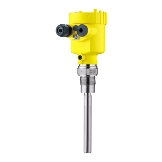
Principle of operation Application area VEGAVIB 61 is a point level sensor with vibrating rod for level detec- tion. It is designed for industrial use in all areas of process technology and is preferably used for bulk solids. -
Page 8: Adjustment
Solid detection in water If VEGAVIB 61 was ordered for solid detection in water, the vibrating rod is calibrated to the density of water. If covered by water (density: 1 g/cm³/0.036 lbs/in) VEGAVIB 61 signals "uncovered". Only if the vibrating element is also covered with solids (e.g. - Page 9 Protected against solar radiation • Avoiding mechanical shock and vibration • Storage and transport Storage and transport temperature see chapter "Supplement - temperature Technical data - Ambient conditions" • Relative humidity 20 … 85 % VEGAVIB 61 • Two-wire 8/16 mA...
-
Page 10: Mounting
You can find the specifications in chapter "Technical data" and on the nameplate. Switching point In general, VEGAVIB 61 can be installed in any position. The instru- ment only has to be mounted in such a way that the vibrating element is at the height of the desired switching point. -
Page 11: Mounting Instructions
Fig. 3: Horizontal installation Protective sheet Concave protective sheet for abrasive solids If such an installation location should be necessary, mount a suitable protective sheet above or in front of the vibrating element, see illustra- tion "a"). VEGAVIB 61 • Two-wire 8/16 mA... - Page 12 The vibrating rod must be mounted in a way that takes the arrange- ment of the filling and emptying apertures into account. To compensate measurement errors caused by the material cone in cylindrical vessels, the sensor must be mounted at a distance of d/6 from the vessel wall. Fig. 4: Filling and emptying centred VEGAVIB 61 • Two-wire 8/16 mA...
- Page 13 VEGAVIB 61 Discharge opening Filling opening Horizontal mounting To achieve a very precise switching point, you can install VEGAVIB 61 horizontally. However, if the switching point can have a tolerance of a few centimeters, we recommend mounting VEGAVIB 61 approx. 20° inclined to the vessel bottom to avoid buildup. VEGAVIB 61 • Two-wire 8/16 mA...
- Page 14 Baffle protection against In applications such as grit chambers or settling basins for coarse falling rocks sediments, the vibrating element must be protected against damage with a suitable baffle. This baffle must be manufactured by you. > 125 mm (> 5") Fig. 7: Baffle for protection against mechanical damage VEGAVIB 61 • Two-wire 8/16 mA...
-
Page 15: Connecting To Power Supply
With Ex instruments, the housing cover may only be opened if there is no explosive atmosphere present. Proceed as follows: 1. Unscrew the housing lid 2. Loosen compression nut of the cable gland and remove blind plug VEGAVIB 61 • Two-wire 8/16 mA... -
Page 16: Wiring Plan, Single Chamber Housing
10. If necessary, carry out a fresh adjustment 11. Screw the housing lid back on The electrical connection is finished. Wiring plan, single chamber housing The following illustrations apply to the non-Ex as well as to the Ex-d version. VEGAVIB 61 • Two-wire 8/16 mA... - Page 17 The wiring example is applicable for all suitable signal conditioning instruments. If the mode switch of VEGAVIB 61 is correctly set to "max.", the con- trol lamp on VEGAVIB 61 lights. • red - with submerged vibrating element •...
-
Page 18: Wiring Plan - Version Ip 66/Ip 68, 1 Bar
Wiring plan - version IP 66/IP 68, 1 bar Wire assignment, con- nection cable Fig. 11: Wire assignment, connection cable Brown (+) and blue (-) to power supply or to the processing system Shielding VEGAVIB 61 • Two-wire 8/16 mA... -
Page 19: Setup
• Signal lamp (5) Note: As a rule, always set the mode before starting to set up VEGAVIB 61 . If used on a VEGATOR signal conditioning instrument, always set the mode switch (2) on VEGAVIB 61 to max. mode. -
Page 20: Function Table
6 Setup As a default setting, the potentiometer of VEGAVIB 61 is set to the complete right position (> 0.3 g/cm³/0.0011 lbs/in³). In very light solids you have to turn the potentiometer to the complete left posi- tion (0.02 … 0.1 g/cm³ or 0.0007 … 0.0036 lbs/in³). By doing this, VEGAVIB 61 will be more sensitive and light solids can be detected more reliably. - Page 21 The following table provides an overview of the switching conditions depending on the adjusted mode of the signal conditioning instru- ment and the level. Note: Keep in mind that the mode switch of VEGAVIB 61 must be always set to "max.". Mode on the signal Level...
-
Page 22: Proof Test (Sil)
3 Short interruption of the supply line to the sensor The recurring proof test according to IEC 61508 can be carried out through a short interruption (> 2 seconds) of the supply line to the sensor. This starts a test sequence. VEGAVIB 61 • Two-wire 8/16 mA... - Page 23 Push the test key for > 2 seconds with a suitable object (screwdriver, pen, etc.). When the VEGAVIB 61 is connected to a processing system or an SPLC, you have to interrupt the connection cable to the sensor for > 2 seconds.
- Page 24 8 mA ±1.5 mA 1.5 s ±0.5 s 3. Full signal approx. currentless energized energized 16 mA 1.5 s ±0.5 s ±1.5 mA Starting time of the voltage supply VEGAVIB 61 • Two-wire 8/16 mA...
- Page 25 Test assessment (SPLC) Test passed Status Current value Time False signal < 3.6 mA 1.5 s ±0.5 s Uncovered 8 mA ±1.5 mA 1.5 s ±0.5 s Covered 16 mA ±1.5 mA 1,5 s ±0,5 s VEGAVIB 61 • Two-wire 8/16 mA...
-
Page 26: Maintenance And Fault Rectification
Check the vibrating element and the sensor for buildup ement and remove the buildup if there is any. Wrong mode selected Set the mode switch on VEGAVIB 61 to "max". Set the correct mode on the signal conditioning instrument (A: overfill protection; B: dry run protection). VEGAVIB 61 • Two-wire 8/16 mA... -
Page 27: Exchanging The Electronics Module
6. Pull out the old electronics module 7. Compare the new electronics module with the old one. The type label of the electronics module must correspond to that of the old electronics module. This applies particularly to instruments used in hazardous areas. VEGAVIB 61 • Two-wire 8/16 mA... -
Page 28: How To Proceed If A Repair Is Necessary
Clean the instrument and pack it damage-proof • Attach the completed form and, if need be, also a safety data sheet outside on the packaging • Please contact the agency serving you to get the address for the return shipment. You can find the agency on our home page www.vega.com. VEGAVIB 61 • Two-wire 8/16 mA... -
Page 29: Dismount
WEEE directive. Correct disposal avoids negative effects on humans and the environ- ment and ensures recycling of useful raw materials. Materials: see chapter "Technical data" If you have no way to dispose of the old instrument properly, please contact us concerning return and disposal. VEGAVIB 61 • Two-wire 8/16 mA... -
Page 30: Supplement
Max. lateral load 400 N (90 lbf) Torque for NPT cable glands and Conduit tubes Ʋ Plastic housing max. 10 Nm (7.376 lbf ft) Ʋ Aluminium/Stainless steel housing max. 50 Nm (36.88 lbf ft) VEGAVIB 61 • Two-wire 8/16 mA... -
Page 31: Ambient Conditions
100°C 150°C 200°C 250°C (-58°F) (32°F) (122°F) (212°F) (302°F) (392°F) (482°F) Fig. 48: Process pressure - Process temperature Process temperature Process pressure VEGAVIB 61 of 316L -50 … +150 °C (-58 … +302 °F) Process temperature (thread or flange -50 … +250 °C (-58 … +482 °F) temperature) with temperature adapter (option) VEGAVIB 61 • Two-wire 8/16 mA... - Page 32 < 0.036 Ω/m (0.011 Ω/ft) Ʋ Tensile strength < 1200 N (270 lbf) Ʋ Standard length 5 m (16.4 ft) Ʋ Max. length 1000 m (3280 ft) Max. 20 mm (0.8 in) with product density < 0.03 g/cm³ (0.0011 lbs/in³). Depending on the version M12 x 1, according to ISO 4400, Harting, 7/8" FF. VEGAVIB 61 • Two-wire 8/16 mA...
- Page 33 For that reason the associated approval documents of these instruments have to be carefully noted. They are part of the delivery or can be downloaded under www.vega.com, "VEGA Tools" and "Instrument search" as well as in the general download area.
-
Page 34: Dimensions
(4.06") ø 77 mm ø 84 mm (3.03") (3.31") M20x1,5 M20x1,5 M20x1,5 Fig. 51: Housing versions with protection rating IP 66/IP 68 (1 bar) Stainless steel single chamber (precision casting) Aluminium - single chamber VEGAVIB 61 • Two-wire 8/16 mA... - Page 35 9 Supplement ø 29 mm (1.14") ø16 mm (0.63") Fig. 52: VEGAVIB 61, threaded version G1 (DIN ISO 228/1) G1½ ø 29 mm (1.14") ø16 mm (0.63") Fig. 53: VEGAVIB 61, threaded version G1½ (DIN ISO 228/1) VEGAVIB 61 • Two-wire 8/16 mA...
- Page 36 9 Supplement ø 34 mm (1.34") Fig. 54: Temperature adapter VEGAVIB 61 • Two-wire 8/16 mA...
-
Page 37: Industrial Property Rights
Les lignes de produits VEGA sont globalement protégées par des droits de propriété intellec- tuelle. Pour plus d'informations, on pourra se référer au site www.vega.com. VEGA lineas de productos están protegidas por los derechos en el campo de la propiedad indus- trial. Para mayor información revise la pagina web www.vega.com. - Page 38 Notes VEGAVIB 61 • Two-wire 8/16 mA...
- Page 39 Notes VEGAVIB 61 • Two-wire 8/16 mA...
- Page 40 Subject to change without prior notice © VEGA Grieshaber KG, Schiltach/Germany 2017 VEGA Grieshaber KG Phone +49 7836 50-0 Am Hohenstein 113...
Need help?
Do you have a question about the VEGAVIB 61 and is the answer not in the manual?
Questions and answers