
Related Manuals for Vega VEGATOR 631 Ex


Summary of Contents for Vega VEGATOR 631 Ex
- Page 1 Operating Instructions VEGATOR 631 Ex Signal conditioning instrument Signal conditioning instruments and communication...
-
Page 2: Table Of Contents
Supplement Technical data ......29 VEGATOR 631 Ex • Signal conditioning instrument... - Page 3 Contents Supplementary documentation Information: Supplementary documents appropriate to the ordered version come with the delivery. You can find them listed in chapter "Product description". VEGATOR 631 Ex • Signal conditioning instrument...
-
Page 4: About This Document
This symbol indicates special instructions for Ex applications. List The dot set in front indicates a list with no implied sequence. à Action This arrow indicates a single action. Sequence Numbers set in front indicate successive steps in a procedure. VEGATOR 631 Ex • Signal conditioning instrument... -
Page 5: For Your Safety
During work on and with the device the required personal protective equipment must always be worn. 2.2 Appropriate use VEGATOR 631 Ex is a universal signal conditioning instrument for connection of a level switch. You can find detailed information on the application range in chapter "Product description". -
Page 6: Ce Conformity
2 For your safety 2.5 CE conformity This device fulfills the legal requirements of the applicable EC guidelines. By attaching the CE mark, VEGA provides a confirmation of successful testing. You can find the CE conformity declaration in the download area of www.vega.com. -
Page 7: Product Description
Ex separating chamber with Ex version Terminal socket Transparent cover Type label The type label contains the most important data for identification and use of the instrument: Article number Serial number Technical data Article numbers documentation VEGATOR 631 Ex • Signal conditioning instrument... -
Page 8: Principle Of Operation
The serial number allows you to access the delivery data of the instrument via www.vega.com, "VEGA Tools" and "serial number search". 3.2 Principle of operation VEGATOR 631 Ex is a single signal conditioning instrument for Application area processing the signals of conductive probes. The VEGATOR 631 Ex signal conditioning instrument powers... - Page 9 Not exposed to corrosive media Protected against solar radiation Avoiding mechanical shock and vibration Storage and transport Storage and transport temperature see chapter "Supplement - temperature Technical data - Ambient conditions" Relative humidity 20 … 85 % VEGATOR 631 Ex • Signal conditioning instrument...
-
Page 10: Mounting
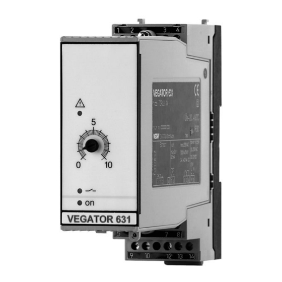
VEGATOR 631 Ex signal conditioning instrument with plug-in socket Installation location for mounting on carrier rail according to EN 50022. The front plate of VEGATOR 631 Ex can be provided with a lead- Transparent cover sealable transparent cover to protect the instrument against unau- thorised or inadvertent adjustment. - Page 11 The plug-in socket is provided with coded pins that can be inserted to prevent accidental interchanging of the various instrument types. With a VEGATOR 631 Ex in Ex version, the supplied coded pins (type coded pin and Ex coded pin) must be inserted by the user according to the below chart.
- Page 12 4 Mounting Fig. 4: Plug-in socket VEGATOR 631 Ex Ex separating chamber Ex coding with Ex version (A) Type coding for VEGATOR 631 Ex (3) Bridges for looping the operating voltage VEGATOR 631 Ex • Signal conditioning instrument...
-
Page 13: Connecting To Power Supply
Connect the sensor cable to terminal 1 and 3 (see the following wiring plans) Connect power supply (switched off) to terminal 9 and 10 Insert VEGATOR 631 Ex into the plug-in socket and screw it down tightly The electrical connection is finished. -
Page 14: Wiring Plan
(above the sensor terminals). The pins for type and Ex coding must also be inserted correctly. 5.3 Wiring plan Limit level measurement (–) Fig. 5: Limit level measurement Relay output Power supply Transistor output Mass max. Probe, e.g. EL1 VEGATOR 631 Ex • Signal conditioning instrument... - Page 15 Probe, e.g. EL3 Note: Mutiple rod probes connected to several signal conditioning instru- ments or to a multiple channel instrument need a ground rod to keep the signal conditioning instruments from influencing each other. VEGATOR 631 Ex • Signal conditioning instrument...
- Page 16 9 10 1314 9 10 1314 (–) (–) Fig. 7: Two-point control with overfill protection Relay output Power supply Transistor output Max. overfill protection Min. Max. Mass Probe, e.g. EL3 Overfill protection Min./max. control VEGATOR 631 Ex • Signal conditioning instrument...
- Page 17 Fig. 8: Circuit of the transistor outputs VEGATOR 631 Ex VEGATOR 631 Ex The resistor R serves as short-circuit protection. 47 Ω 0.25 W 150 Ω 0.75 W 330 Ω 1.5 W 560 Ω 2.2 W VEGATOR 631 Ex • Signal conditioning instrument...
-
Page 18: Set Up
Control lamp - Power supply (LED green) Bridge for adjusting the fault signal Terminals for probe Function coding Ex version Instrument coding Sockets for bridges 10 Transistor output 11 Relay output 12 Power supply VEGATOR 631 Ex • Signal conditioning instrument... -
Page 19: Adjustment Elements
Fault on the sensor circuit due to sensor failure or line break The relay deenergises in case of failure Yellow Relay control lamp The yellow relay control lamp reacts depending on the set mode (A/B) VEGATOR 631 Ex • Signal conditioning instrument... - Page 20 Switch Time 12 s 0.2 s off off off off off off off off 12 s off off 14 s off 18 s off 20 s VEGATOR 631 Ex • Signal conditioning instrument...
- Page 21 If a measuring system is used as part of an overfill protection system, the bridge on the signal conditioning instrument must not be closed. With Ex probes, the resistor in the probe housing is already present. VEGATOR 631 Ex • Signal conditioning instrument...
- Page 22 6 Set up You can find the electrical connection of VEGATOR 631 Ex in the operating instructions manual of the corresponding signal conditioning instrument. Line monitoring With Ex versions, this 220 kΩ resistor is already integrated ex factory in the connection housing of the probe. The Ex measuring system (max.
-
Page 23: Switching Point Adjustment
Connect the signal conditioning instrument to power supply Turn the potentiometer to position 0 Fill the vessel until the max. electrode is covered approx. 1 cm by the product Turn the potentiometer slowly clockwise until the yellow signal lamp extinguishes VEGATOR 631 Ex • Signal conditioning instrument... - Page 24 This switching condition remains until the level falls below the position of the min. electrode, i.e. the relay energizes at min. level and the transistor conducts. VEGATOR 631 Ex • Signal conditioning instrument...
- Page 25 6 Set up The relay deenergises again at max. level and the transistor blocks. VEGATOR 631 Ex • Signal conditioning instrument...
-
Page 26: Maintenance And Fault Rectification
24 hour service hotline However, should these measures not be successful, call the VEGA service hotline in urgent cases under the phone no. +49 1805 858550. The hotline is available to you 7 days a week round-the-clock. Since we offer this service world-wide, the support is only available in the... -
Page 27: Instrument Repair
If a repair is necessary, please proceed as follows: You can download a return form (23 KB) from our Internet homepage www.vega.com under: "Downloads - Forms and certificates - Repair form". By doing this you help us carry out the repair quickly and without having to call back for needed information. -
Page 28: Dismounting
Correct disposal avoids negative effects to persons and environment and ensures recycling of useful raw materials. Materials: see chapter "Technical data" If you have no possibility to dispose of the old instrument professionally, please contact us concerning return and disposal. VEGATOR 631 Ex • Signal conditioning instrument... -
Page 29: Supplement
Mode A/B switch (A - max. detection or overfill protection, B - min. detection or dry run protection) 500 ms Integration time 1 spdt for each output Contact Contact material AgNi, hard gold-plated VEGATOR 631 Ex • Signal conditioning instrument... - Page 30 Electrical separating measures power supply, sensor input, level relay and tran- sistor output Approvals ATEX ATEX II (1) G [EEx ia] IIC Others Ship approval Deviating data in Ex applications: see separate safety instructions. VEGATOR 631 Ex • Signal conditioning instrument...
- Page 31 12 13 14 134 mm (5.28") 36 mm (1.42") Fig. 16: Dimensions VEGATOR 631 Ex Transparent cover Carrier rail 35 x 7.5 or 35 x 15 according to EN 50022 Ex separating chamber VEGATOR 631 Ex • Signal conditioning instrument...
- Page 32 All statements concerning scope of delivery, application, practical use and operating conditions of the sensors and processing systems correspond to the information avail- able at the time of printing. © VEGA Grieshaber KG, Schiltach/Germany 2009 23440-EN-090130 Subject to change without prior notice...
Need help?
Do you have a question about the VEGATOR 631 Ex and is the answer not in the manual?
Questions and answers