
Related Manuals for Vega VEGABOX 03


Summary of Contents for Vega VEGABOX 03
- Page 1 Operating Instructions Breather housing with ventilation filter VEGABOX 03 Document ID: 45925...
-
Page 2: Table Of Contents
Supplement Technical data ........................ 20 Dimensions ........................22 Safety instructions for Ex areas Please note the Ex-specific safety information for installation and op- eration in Ex areas. These safety instructions are part of the operating instructions manual and come with the Ex-approved instruments. Editing status: 2013-11-18 VEGABOX 03 •... -
Page 3: About This Document
The dot set in front indicates a list with no implied sequence. → Action This arrow indicates a single action. Sequence of actions Numbers set in front indicate successive steps in a procedure. Battery disposal This symbol indicates special information about the disposal of bat- teries and accumulators. VEGABOX 03 •... -
Page 4: For Your Safety
During work on and with the device the required personal protective equipment must always be worn. Appropriate use The VEGABOX 03 is used as breather housing for suspension pressure transmitters VEGAWELL 52 and terminal housing for radar sensors VEGAPULS WL 61. -
Page 5: Ce Conformity
That is why we have introduced an environment management system with the goal of continuously improving company environmental pro- tection. The environment management system is certified according to DIN EN ISO 14001. Please help us fulfill this obligation by observing the environmental instructions in this manual: • Chapter "Packaging, transport and storage" • Chapter "Disposal" VEGABOX 03 •... -
Page 6: Product Description
– if necessary, further certificates Principle of operation Application area The VEGABOX 03 is used as breather housing in protection IP 66/ IP 67 for hydrostatic pressure transmitters VEGAWELL 52. In this ver- sion, the housing is equipped with a filter element for ventilation. The VEGABOX 03 is used as terminal housing in protection IP 66/ IP 68 (0.2 bar) for radar sensors VEGAPULS WL 61. -
Page 7: Packaging, Transport And Storage
3 Product description Fig. 1: Application example: Use of a VEGAWELL 52 with VEGABOX 03 Fig. 2: Application example: Use of a VEGAPULS WL 61 with VEGABOX 03 Packaging, transport and storage Packaging Your instrument was protected by packaging during transport. Its capacity to handle normal loads during transport is assured by a test based on ISO 4180. - Page 8 Not exposed to corrosive media • Protected against solar radiation • Avoiding mechanical shock and vibration • Storage and transport Storage and transport temperature see chapter "Supplement - temperature Technical data - Ambient conditions" • Relative humidity 20 … 85 % VEGABOX 03 •...
-
Page 9: Mounting
82 mm (3.23") 10 mm (0.39") Fig. 3: Drilling dimensions for the VEGABOX 03 for wall mounting Carrier rail mounting - The VEGABOX 03 with plastic housing is suitable for direct carrier rail Plastic housing mounting. VEGABOX 03 •... - Page 10 The kit consists of an steel housing adapter plate and four mounting screws M5 x 12. The adapter plate is screwed to the socket of VEGABOX 03 by the user. Fig. 5: VEGABOX 03 with aluminium and stainless steel housing for carrier rail...
- Page 11 4 Mounting Fig. 6: VEGABOX 03 for tube mounting 4 screws M5 x 100 Mounting brackets Tube (diameter 1" to 2") VEGABOX 03 •...
-
Page 12: Connecting To The Sensor
If screened cable is necessary, connect the cable screen on both grounding ends to ground potential. In the VEGABOX 03, the screen must be connected directly to the internal ground terminal. The ground termi- nal on the outside of the housing must be connected to the potential equalisation (low impedance). - Page 13 9. Connect the screen to the internal ground terminal, connect the outer ground terminal to potential equalisation 10. Tighten the compression nut of the cable entry gland. The seal ring must completely encircle the cable 11. Screw the housing cover back on The connection is finished. VEGABOX 03 •...
-
Page 14: Wiring Plan
Wiring plan - VE- GAWELL 52 4 … 20 mA, 4 … 20 mA/HART Fig. 9: Wiring plan VEGABOX 03 for VEGAWELL 52 4 … 20 mA, 4 … 20 mA/ HART To the sensor To power supply or the processing system... - Page 15 GAWELL 52 4 … 20 mA/ HART Pt 100 – Fig. 10: Wiring plan VEGABOX 03 for VEGAWELL 52 4 … 20 mA/HART Pt 100 To the sensor To power supply or the processing system Connection lines resistance thermometer Pt 100...
- Page 16 NECT to VEGABOX 03 Fig. 12: Connection example: Connection of a VEGACONNECT to the VEG- ABOX 03 Sensor Connection cable, sensor - VEGABOX 03 VEGABOX 03 Voltage supply/signal output sensor (depending on the power supply, exter- nal communication resistor > 250 Ω required)
-
Page 17: Setup
6 Setup Setup Setup steps Setup and adjustment are carried out according to the operating instructions manual of the respective sensor. VEGABOX 03 •... -
Page 18: Maintenance And Fault Rectification
24 hour service hotline Should these measures not be successful, please call in urgent cases the VEGA service hotline under the phone no. +49 1805 858550. The hotline is also available outside normal working hours, seven days a week around the clock. -
Page 19: Dismounting
Pass the instrument directly on to a spe- cialised recycling company and do not use the municipal collecting points. These may be used only for privately used products according to the WEEE directive. VEGABOX 03 •... -
Page 20: Supplement
Options of the cable entry Ʋ Cable entry M20 x 1.5, ½ NPT Ʋ Cable gland M20 x 1,5; ½ NPT (cable ø see below table) Ʋ Blind plug M20 x 1.5; ½ NPT Ʋ Closing cap ½ NPT VEGABOX 03 •... - Page 21 Instruments with approvals can have different technical data depending on the version. For that reason the associated approval documents of these instruments must be carefully noted. They are part of the delivery or can be downloaded under www.vega.com and "VEGA Tools" as well as under "Downloads" and "Approvals". VEGABOX 03 •...
-
Page 22: Dimensions
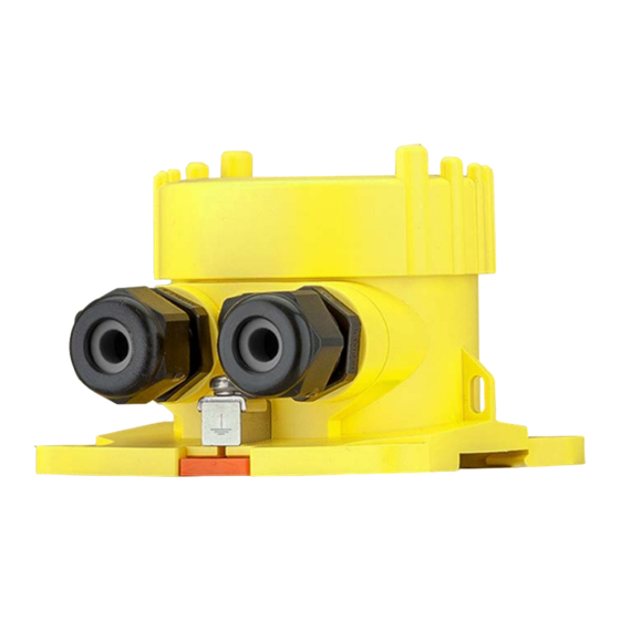
Dimensions VEGABOX 03 - Plastic housing ø 79 mm ~ 69 mm (3.11") (2.72") 97 mm (3.82") Fig. 13: VEGABOX 03 with plastic housing VEGABOX 03 - Aluminium housing ø 86 mm ~ 75,2 mm (3.39") (2.95") 97 mm (3.82") Fig. - Page 23 (3.39") (2.95") 97 mm (3.82") Fig. 15: VEGABOX 03 with stainless steel precision casting housing Mounting elements 97 mm (3.82") 82 mm 7 mm (3.23") (0.28") Fig. 16: Adapter plate for carrier rail mounting of VEGABOX 03 VEGABOX 03 •...
- Page 24 9 Supplement 48...84 mm (1.89"...3.31") 20 mm 20 mm (0.79") (0.79") Fig. 17: Brackets for tube mounting of VEGABOX 03 VEGABOX 03 •...
- Page 25 Les lignes de produits VEGA sont globalement protégées par des droits de propriété intellec- tuelle. Pour plus d'informations, on pourra se référer au site www.vega.com. VEGA lineas de productos están protegidas por los derechos en el campo de la propiedad indus- trial. Para mayor información revise la pagina web www.vega.com.
- Page 26 Notes VEGABOX 03 •...
- Page 27 Notes VEGABOX 03 •...
- Page 28 Subject to change without prior notice © VEGA Grieshaber KG, Schiltach/Germany 2013 VEGA Grieshaber KG Phone +49 7836 50-0 Am Hohenstein 113...
Need help?
Do you have a question about the VEGABOX 03 and is the answer not in the manual?
Questions and answers