Table of Contents
Advertisement
Quick Links
Advertisement
Table of Contents
Troubleshooting

Related Manuals for ELCOM EURO-2500


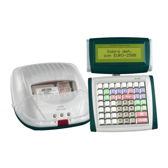
Summary of Contents for ELCOM EURO-2500
- Page 1 -2500 Euro-2500TX Service manual manual version 2.0.5 © Elcom, s. r. o.
- Page 2 This manual was not subject to any language revision. This manual, as also any of its parts, must not be copied, reporo- duced or otherwise distributed without editor‘s consent. All rights reserved. Elcom s. r. o. 2003...
-
Page 3: Table Of Contents
© Elcom s. r. o. Service manual Table of contents 1 Introduction ................11 1.1 Technical parameters for ECR Euro-2500TX . - Page 4 © Elcom s. r. o. 4.10 NiCd accumulator exchange............. . .39 4.11 Displays reinstallation .
- Page 5 © Elcom s. r. o. Service manual 5.10 ECR tests ................. . 74 5.10.1 Printer tests .
- Page 6 Service manual Service manual Service manual Service manual Service manual Service manual Service manual Service manual © Elcom s. r. o. Euro 2500...
- Page 7 © Elcom s. r. o. Service manual Table of figures Fig. 1.1: Block chart of Euro 2500-TX cash register ........... . 11 Fig.
- Page 8 Service manual © Elcom s. r. o. Fig. 4.7: Pull the ratchets lightly along the arrows and pull out the cutter......35 Fig.
- Page 9 © Elcom s. r. o. Service manual Table of tables Tab. 2.1: Pin description for E-2500N ..............15 Tab.
- Page 10 © Elcom s. r. o. Tab. 6.3: Bill of material for the button bar PCB ............89 Tab.
-
Page 11: Introduction
© Elcom s. r. o. Service manual 1 Introduction 1.1 Technical parameters for ECR Euro-2500TX 1.1 Technical parameters for ECR Euro-2500TX Euro-2500TX is the electronic cash register (henceforth ECR) characterised by following parameters: • primary power supply external power supply 230 V, 50–60 Hz/24 V; 2.08 A •... - Page 12 Service manual Service manual Service manual Service manual Service manual Service manual Service manual Service manual © Elcom s. r. o. Euro 2500...
-
Page 13: Circuits Schemes And Fuctions
© Elcom s. r. o. Service manual 2 Circuits schemes and fuctions 2.1 Power supply circuits 2.1 Power supply circuits 2.1.1 External power supply 2.1.1 External power supply The switched impulse power supply circuit ANITA 100–240 V; 47–63 Hz/24 V; 2.08 A. Its basic function is to generate unidirec- tional voltage for the correct ECR function from the mains AC voltage. -
Page 14: Power Supply +3.3 V
Service manual © Elcom s. r. o. 2.1.5 Power supply +3.3 V 2.1.5 Power supply +3.3 V This +3.3 V voltage is used only to power the EPM3032ATC44-10 circuit. Fig. 2.4: Power supply +3,3 V 2.2 The microcontroller and its support circuits 2.2 The microcontroller and its support circuits... -
Page 15: Tab. 2.1: Pin Description For E-2500N
© Elcom s. r. o. Service manual Pin # Description Type Signal description VRAM +5V power supply FAULT Printer failure signaling KB-DATA External PC keyboard data Control of 1.direct phase of 2.printer stepping motor Control of 2.direct phase of 2.printer stepping motor... -
Page 16: Memory Circuits
Service manual © Elcom s. r. o. Pin # Description Type Signal description PAP2 Scanning paper ribbon presence in printer Scanning printer head temperature Scanning printer head machinery position POSUC Receipt shifting request POSZU Journal shifting request Scanning auto cutter final position... -
Page 17: Start And Turning Off Of The System
© Elcom s. r. o. Service manual To preserve the data in the RAM memory while the ECR is off, the memory power supply is backed up from the accumula- tor. 2.2.3 Start and turning off of the system 2.2.3 Start and turning off of the system The mostly importat system states are its start and its turning off. -
Page 18: Tab. 2.2: Pin Description For U4 Circuit
Service manual © Elcom s. r. o. • error signals • printer status signals • paper tape feed signals • paper cutter end position signal All these functions are provided by the circuits described in the following subchapters. Fig. 2.10: Printing control signals... - Page 19 © Elcom s. r. o. Service manual Pin # Description Type Signal description 0V power supply Data input from data bus Circuit activation for printer hour and data production Address input Data input from data bus 0V power supply VCC3V3 +3.3V power supply...
-
Page 20: Tab. 2.4: Motor Conection
Service manual © Elcom s. r. o. Fig. 2.12: Control circuit for the journal winding motor Fig. 2.13: Control circuit for the paper tape cutter Fig. 2.14: Paper cutter end position signal DC Motor W-MOT ��� ������ ����� + (red) –... -
Page 21: Displays
© Elcom s. r. o. Service manual Fig. 2.18: Printer connector connection 2.3.2 Displays 2.3.2 Displays The Euro-2500TX ECR has got one internal segment display for the customer. It is possible to connect two external displays to the ECR, either alphanumerical or segment LCD. As used, one of those is the cashier’s display. The second one needn’t to be used, but can be used as the secondary customer display. - Page 22 Service manual © Elcom s. r. o. Fig. 2.19: Segment display and the NJU6432B display controller interconnection Fig. 2.20: Connection for the display controller NJU6432B Fig. 2.21: Internal customer display interface Euro 2500...
- Page 23 © Elcom s. r. o. Service manual Segment display communicates with the main microcontroller E-2500N using the LCD-SEL, LCD-CLK and D-LCD signals. Segment display module Segment display module This module has the same connection as the internal segment display. It differs only in the cable and connector type because it is supplied as an ECR accessory.
-
Page 24: Communication Circuits
Service manual © Elcom s. r. o. 2.3.3 Communication circuits 2.3.3 Communication circuits The Euro-2500TX ECR is by default equipped with the communication circuits for the PC and bar-code scanner and further two RS232 channels e. g. for the electronic scales and EFT terminal. - Page 25 © Elcom s. r. o. Service manual U19A U19B & & CS51 74HC00 74HC00 U19D 74HC00 U19C & CS52 74HC00 Fig. 2.26: Communication cir- cuits for the COM3 and COM4 Euro 2500...
-
Page 26: Other Circuits
Service manual © Elcom s. r. o. 2.3.4 Other circuits 2.3.4 Other circuits Other ECR circuits include: a) Buzzer control. The buzzer is used by the Euro-2500TX ECR to acoustically signal the pressing of the key and as a warning device. -
Page 27: Thermal Printer
© Elcom s. r. o. Service manual 3 Thermal printer 3.1 Basic specification 3.1 Basic specification Model SEIKO LTP2W42 Printing method Thermal dot printing Dots per row 864 dots Usable dots per row 784 dots Print density 8 dots/mm Top printing speed... -
Page 28: Data Processing In The Printing Head
Service manual Service manual © Elcom s. r. o. the P-LATCH signal. The head-activating signals (STB1 and STB2) will ensure that the data in the latch register will be prin- the P-LATCH signal. The head-activating signals (STB1 and STB2) will ensure that the data in the latch register will be prin- ted. -
Page 29: Paper Feeding
© Elcom s. r. o. Service manual 3.3 Paper feeding 3.3 Paper feeding The feeding of paper in POS-4000 is taken care of by twin stepping motors. One feed step will feed 0.125 mm of paper tape. 3.3.1 Stepping motor specification 3.3.1 Stepping motor specification... -
Page 30: Overall Time Diagram
Service manual Service manual Service manual Service manual Service manual Service manual © Elcom s. r. o. 3.5 Overall time diagram 3.5 Overall time diagram 3.5 Overall time diagram 3.5 Overall time diagram 3.5 Overall time diagram 3.5 Overall time diagram ��������������... -
Page 31: Stepping Motors' Connectors
© Elcom s. r. o. Service manual Pin # Pin desc. Function STB2 Activation signal for second half od thermal elements P-LATCH Latching signal input PRNCLK Printer clock signal input Serial data input +24V +24V Tab. 3.5: Thermal head connector pins’ description (cntd.) 3.5.2 Stepping motors’... -
Page 32: Tab. 3.8: Paper Tape Cutter Specification
Service manual Service manual Service manual Service manual Service manual Service manual Service manual Service manual Service manual Service manual © Elcom s. r. o. Item Specification Model ACU2324A Cutting method gillotine scissors Cutting slit width 85 mm Paper thickness 65–125 mm... -
Page 33: Reinstallation Of Individual Modules
© Elcom s. r. o. Service manual 4 Reinstallation of individual modules Before the actual reinstallation of individual modules, please pay attention to the following safety precautions: • If you reinstall any ECR module or accessory that already has been in use, it is recommended to ensure yourself whether the current sale is finished and the Z-report has been performed. -
Page 34: Separating The Main Pcb Case
Service manual Service manual Service manual © Elcom s. r. o. 4.2 Separating the main PCB case 4.2 Separating the main PCB case 1) Open the top ECR cover. 2) Release the fixing screws that hold the main PCB case underneath the bottom ECR case as shown in the picture. -
Page 35: Reinstallation Of The Printer, Printer Pcb And The Paper Tape Cutter
© Elcom s. r. o. Service manual 4.4 Reinstallation of the printer, printer PCB and the paper tape cutter 4.4 Reinstallation of the printer, printer PCB and the paper tape cutter 1) Separate the printer cover from the bottom case (see chapter 4.1). -
Page 36: Motor Reinstallation
Service manual Service manual Service manual © Elcom s. r. o. 4.5 Motor reinstallation 4.5 Motor reinstallation 1) Make sure that the ECR is turned off and the external power adapter is disconnected. 2) Remove the top ECR cover (chapter 4.3) 3) Release printer PCB cover (chapter 4.1) so you could disconnect the winding motor connector. -
Page 37: Reinstalling The Main Pcb
© Elcom s. r. o. Service manual 4.6 Reinstalling the main PCB 4.6 Reinstalling the main PCB Note: It is possible to reinstall the main PCB only when the ECR is turned off and the external power adapter is disconnected. -
Page 38: Damaged Sram Reinstallation; Ecr Reset
Service manual Service manual Service manual © Elcom s. r. o. 4.8 Damaged SRAM reinstallation; ECR reset 4.8 Damaged SRAM reinstallation; ECR reset 1) Make sure, that the ECR is turned off and the external power adapter is disconnected. 2) Pull out the main unit (chapter 4.2) and remove the top cover of the electronics case. -
Page 39: Nicd Accumulator Exchange
© Elcom s. r. o. Service manual 4.10 NiCd accumulator exchange 4.10 NiCd accumulator exchange 1) Perform the daily and monthly report and back up all the data to the PC, if there are any valid data stored in the ECR. -
Page 40: Tab. 4.5: Table Of Viewed Parts
Service manual Service manual Service manual Service manual Service manual Service manual Service manual © Elcom s. r. o. ���������������������� ������������������� ������������������ Fig. 4.17: Customer segment display fitting Fig. 4.18: Screws holding the customer display cover ��������������� Fig. 4.19: Butterfly screw Fig. -
Page 41: Connectors
© Elcom s. r. o. Service manual 4.12 Connectors 4.12 Connectors Main PCB connectors: Note: Connector rearrangement shall be done only while the ECR is turned off. 1) Make sure, that the ECR is turned off and the external power adapter is disconnected. -
Page 42: External Devices Connectors Mounting
Service manual Service manual Service manual © Elcom s. r. o. 4.13 External devices connectors mounting 4.13 External devices connectors mounting Note: Mounting of the external devices connectors shall be performed only when the ECR is turned off. 1) Make sure, that the ECR is turned off and the external power adapter is disconnected. -
Page 43: Connection For External Drawers And Keyboard
© Elcom s. r. o. Service manual 4.14 Connection for external drawers and keyboard 4.14 Connection for external drawers and keyboard Conditions for an external drawer to be safely connected to the Euro-2500TX ECR: a) solenoid driven opening mechanism, no other electronics or interface b) solenoid at maximum 24 V at maximum current 1 A c) solenoid resistance minimum 24 Ω... -
Page 44: Connection Of External Printers
Service manual © Elcom s. r. o. Note 2: The displays will be automatically activated after they are plugged in and ECR is turned on. Note 3: The customer display must be connected; without this display the ECR won’t work. -
Page 45: Connection Of The Electronic Scales
© Elcom s. r. o. Service manual 4.17 Connection of the electronic scales 4.17 Connection of the electronic scales The ECR is capable of communicating with maximum two electronic scales. Choose the scales type in the ECR service mode and the ECR sets all the communication parameters automatically. -
Page 46: Installation Of Additional Communication Module Com5 - Serial Interface Rs-422
Service manual Service manual Service manual Service manual Service manual © Elcom s. r. o. ������������ Fig. 4.30: Connection of the EFT terminal 4.19 Installation of additional communication module COM5 – serial interface RS-422 – serial interface RS-422 1) Turn ECR off and disconnect the external power adapter. -
Page 47: The Serial Interfaces Cabling
© Elcom s. r. o. Service manual �������������� ��� ����� ������ ����� ��� ����� ������ ����� ��������������������������������� ���������� ��������������� Fig. 4.33: COM5 cable construction Index Quantity Description Code Srew M3x8 Nut M3 Washer flexible Connector 5-pin F Tab. 4.6: Table of viewed parts Fig. - Page 48 Pin can be properly reassembled. Pin descriptions are valid only for the descriptions are valid only for the ��� converters supplied by the Elcom converters supplied by the Elcom company (Duha system). Maximum interconnection cable Maximum interconnection cable...
-
Page 49: Ecr Service Mode
© Elcom s. r. o. Service manual 5 ECR service mode The service mode allows you to perform: - actual ECR tests - set the communication parameters for individual devices - set the ECR system flags - programming - service functions The service mode is accessible only after the standard password (maximum 6 characters long) was entered and this pass- word can be changed as you wish. - Page 50 Service manual Service manual Service manual Service manual Service manual Service manual Service manual Service manual © Elcom s. r. o. 5. ID numbers 1. Scales 6. Text logos 1. Morcan 7. Function texts 2. Martes 8. ECR num.,clear. 3. Macca 9.
-
Page 51: Master Reset
© Elcom s. r. o. Service manual 1. Print char set 965. Other tests 2. Prn.head test 1. Real time circuit 3. Paper sensor 2. Buzzer 4. Cutter 3. Drawer 1. Full cut 4. Jumpers 2. Partial cut 5. RFID 962. -
Page 52: Programming In The P Mode
Service manual Service manual Service manual Service manual Service manual © Elcom s. r. o. Numeral Default Description Available values Date - permission to program the date in the programming mode 0 – programming is forbid- Time - permission to program the time in the programming mode den, 1 –... -
Page 53: Printing Settings 2
© Elcom s. r. o. Service manual Numeral Default Description Available values 0 – both journal and receipt, 1 – receipt, Printing in the registration mode. 2 – journal, 3 – no printing 0 – both journal and receipt, 1 – receipt, Printing in the training mode. -
Page 54: Direct Keys' Shift Value
In such cases contact the Elcom ended by PLU, EAN, direct key PLU or scanned bar-code PLU company service. -
Page 55: Customer Description Lines
© Elcom s. r. o. Service manual 2. Enter the old password and press O NTER NTER 1.Line desc. > Old password Name 5.4.14 Application texts 5.4.14 Application texts 3. Enter the new password (not more than 6 numerals) and... -
Page 56: Setting The Fiscal Core (Fc) Flags
Service manual Service manual Service manual © Elcom s. r. o. 5.5 Setting the fiscal core (FC) flags 5.5 Setting the fiscal core (FC) flags Look up “FC settings” in the service mode menu or enter the code 920 and press O 920.FC settings... -
Page 57: Secondary Currency
© Elcom s. r. o. Service manual Display Default Description Available values exchange rate of the secondary currency to the master cur- 0.900 101– 1012 1.Rate rency with fixed three decimal places * secondary currency activity (D) 0 – not actvie, 1 – active 2.Activity... -
Page 58: Tab. 5.9: Flags For Menu 920/3-Fc Miscellaneous Settings
Service manual Service manual Service manual Service manual Service manual Service manual Service manual © Elcom s. r. o. Display Default Description Available values number of decimal places for quantity rounding 0 – 3 (display shows the rounded value) 1.Round QNT 0 –... -
Page 59: Taxes
© Elcom s. r. o. Service manual 5.5.4 Taxes 5.5.4 Taxes Save settings? > 1. Look up “Taxes” in the FC settings submenu or enter the code 4 and press O NTER NTER 5.5.5 Taxpayer’s ID numbers 5.5.5 Taxpayer’s ID numbers 920.FC settings... -
Page 60: Tab. 5.12: Settings For Menu 920/6-Fc Text Logos
Service manual Service manual Service manual Service manual Service manual Service manual Service manual Service manual © Elcom s. r. o. Display Default Description Available values 29/33 characters (depends on top logo lines 1-6 1.-6.Top logo 1-6 printing mode) number of printed top logo rows 0 –... -
Page 61: Function Texts
© Elcom s. r. o. Service manual 1.Top logo 1 920.FC settings ELCOM, s.r.o. 8.ECR num.,clear. 5.5.7 Function texts 5.5.7 Function texts 2. Select the item you want to change using the arrows or 1. Look up “Function texts” in the FC settings submenu or enter its code and press O ). -
Page 62: Hardware
Service manual Service manual Service manual Service manual Service manual Service manual Service manual © Elcom s. r. o. time is displayed if the down arrow is pressed during the time setting. 10.HW 3.Journal's font 0 9.Date, time > 1.Edit date 3. -
Page 63: Limits
© Elcom s. r. o. Service manual 3. Using the up and down arrows select the desired value or enter it using the keyboard. Press O 10,000,000,000.00 NTER NTER 5000000000.00GBP 2.Report's print 1 > 0.All Z on L&R side Note: The values are entered with two decimal places 5.5.13 Format... -
Page 64: Top Graphical Logo
Service manual Service manual Service manual Service manual Service manual Service manual © Elcom s. r. o. 3. Enter the desired value using the keyboard. Press O 13.Formats NTER 10.Unit.prc.form. 1 1.Logo height 240 5.5.14 Top graphical logo 5.5.14 Top graphical logo 1. -
Page 65: Fiscal Set
© Elcom s. r. o. Service manual 2. Select the item you want to change using the arrows or shown behind the text is the current setting. See table enter its code and press O ). The number 5.22 for details on individual menu items. -
Page 66: Setting The Communication Parameters
Service manual Service manual Service manual Service manual © Elcom s. r. o. 5.6 Setting the communication parameters 5.6 Setting the communication parameters formant to selected peripheral own speed and press O The correct values of communication parameters are vital to ensure the correct ECR communication with its peripherals. - Page 67 © Elcom s. r. o. Service manual sired parity check and press O ). Values: NTER NTER 933.Printers > 0 – none (no parity check), 1 – even, 2 – odd. KITCHEN KITCHEN 3.Parity 0 2. Set the printer type by looking up “Printer type” or enter-...
-
Page 68: Setting The Communication Parameters For Scales
Service manual Service manual Service manual © Elcom s. r. o. 14. Set the spacing in-between receipts. Look up “Lines feed” 18. Restore the default values. Look up “Default” using arrows or enter the code 8 and press O ). Enter or enter the code 10 and press O ). -
Page 69: In-Line
© Elcom s. r. o. Service manual To set the other tables, apply the above procedure accord- fault demo data. It is recommended to back-up all the pro- ingly. Only select the desired table in step 1. Apply changes grammed data (PLU, DPT, cashiers…) into the PC. After the to all relevant tables and only afterwards use the “Update all”... -
Page 70: Ecr Service Mode Printout
Service manual Service manual Service manual © Elcom s. r. o. 5. If the link address was changed, look up “Link address” or Note: Device names and link addresses have to be unique. enter code 2 and press O New settings are applied after the ECR was turned off and... - Page 71 © Elcom s. r. o. Service manual Num.5 flag Num.5 flag Num.5 flag Num.5 flag CUSTOMER CREDIT CUSTOMER CREDIT CUSTOMER CREDIT CUSTOMER CREDIT Num.6 flag RtnPack Num.7 flag INVALID RECEIPT 920/5 920/7 Num.8 flag PRINTING INTERRUPTED Num.9 flag SALE INTERRUPTED...
- Page 72 Service manual Service manual Service manual Service manual Service manual Service manual Service manual Service manual © Elcom s. r. o. Formats Active Taxes print out Protocol Not in use Baud rate 9600 Dec.separator Parity Thous.sep.prn Stop bits Thous.sep.dsp Data bits Date,time prn.
- Page 73 © © Elcom s. r. o. Elcom s. r. o. Elcom s. r. o. Elcom s. r. o. Elcom s. r. o. Elcom s. r. o. Elcom s. r. o. Elcom s. r. o. Elcom s. r. o. Elcom s. r. o.
-
Page 74: Ecr Tests
Service manual Service manual Service manual Service manual © Elcom s. r. o. 5.10 ECR tests The Euro-2500TX ECR tests allow quick diagnostics of ECR Testing procedure: functions and easier identification of ECR flaws. You can diag- nose the display elements, keyboard keys, printer functions, 1. -
Page 75: Paper Tape Cutter Test
© Elcom s. r. o. Service manual 960.Tests 961.Printer tests 962.Display sets 3.Paper sensor 5.10.2.1 Display communication test 5.10.2.1 Display communication test Testing procedure: 1. Display shows the current status for the paper tape sen- Procedure: sors. 2. Status changes with the inserting or removing the paper Look up “Connection”... -
Page 76: Display Backlight Test
Service manual Service manual Service manual Service manual Service manual Service manual © Elcom s. r. o. 5.10.3.1 Keyboard communication test 5.10.3.1 Keyboard communication test Testing procedure for the external customer alphanumerical display: Procedure: The external customer alphanumerical display gradually dis- plays all its segments fully lighted. -
Page 77: Testing The Com1, Com3, And Com4 Interfaces
© Elcom s. r. o. Service manual Procedure: Printed testing output: Look up “Ser. comm. tests” in the tests submenu using arrows or enter code 964 and press O NTER NTER TEST 964.1 960.Tests 964.Ser.comm.tests 5.10.4.2 Testing the COM2 interface 5.10.4.2 Testing the COM2 interface... -
Page 78: Break Signal Test
Service manual Service manual Service manual © Elcom s. r. o. can be run with the use of the terminal adapter only. Termi- Testing procedure: nal adapter scheme is in the shown picture. 1. The microprocessor sends five break signals through its S oldering s ide serial output to the PC connector. -
Page 79: Buzzer Test
© Elcom s. r. o. Service manual 5.10.5.2 Buzzer test 5.10.5.2 Buzzer test Printed testing output: The buzzer test diagnoses the ECR audio signals. TEST 965.3 Procedure: Look up “Buzzer” in the other tests submenu or enter code 2 and press O... -
Page 80: Checksum Test
Service manual Service manual Service manual Service manual Service manual Service manual © Elcom s. r. o. Procedure: 965.Other tests < Look up “RFID” in the other tests submenu or enter code 5 7.SRAM memory test and press O NTER... -
Page 81: Test Of Data Writing Into Fm
© Elcom s. r. o. Service manual Area Address space Area Address space Printed testing output: 00000–01FFF 10000–11FFF 02000–03FFF 12000–13FFF 04000–05FFF 14000–15FFF TEST 966.1 06000–07FFF 16000–17FFF 08000–09FFF 18000–19FFF 0A000–0BFFF 1A000–1BFFF 0C000–0DFFF 1C000–1DFFF 5.10.6.2 Test of data writing into FM 5.10.6.2 Test of data writing into FM 0E000–0FFFF... -
Page 82: Testing The Fiscal Memory Integrity
Service manual Service manual Service manual Service manual © Elcom s. r. o. Printed testing output: ************************************ address 00020 BA B3 BC B0 B2 68 00 00 * * * * * * * * * * * * * * * * * * * * * * * * * * * * * * * * * * * * * TEST 966.3... - Page 83 © Elcom s. r. o. Service manual Printed testing output: 3. At the end, ECR will print out the test results. Since this test is composite, its printout will be composed of out- puts described above. ******CLEAR DATA INTEGRITY TEST******...
- Page 84 Service manual Service manual Service manual Service manual Service manual Service manual Service manual Service manual © Elcom s. r. o. Euro 2500...
-
Page 85: Bills Of Material And Spare Parts Ordering
© Elcom s. r. o. Service manual 6 Bills of material and spare parts ordering 6.1 Bill of material for main PCB KEYBCON C77 BD2 C75 BD1 C C 8 8 1 1 C C 8 8 6 6 C C 8 8 2 2... - Page 86 Service manual © Elcom s. r. o. Amount Description Signature Jacket Code C4, C5, C8, C9, C10, C11, C12, C13, C14, C17, C18, C19, C20, C21, C22, C23, C26, C28, C37, C41, C43, C45, C47, C53, C54, 100n C55, C56, C57, C58, C59, C60, C61, C62, C63, C64, C66, C67,...
-
Page 87: Bill Of Material For Printer Pcb
© Elcom s. r. o. Service manual Amount Description Signature Jacket Code AVA 5400-2P-S DRW1CON S1G2M M190080 AVA 5400-2P-S DRW2CON S1G2M M190080 BD1, BD2, BD3, BD6, BD7, BD8, BD9, BD10, BD11, BD12, BD13, BD14, BD15, BD16, BD17, BD18, BD19, BD20, BD21,... -
Page 88: Tab. 6.2: Bill Of Material For The Printer Pcb
Service manual © Elcom s. r. o. Amount Description Signature Jacket Code 2PIN TRNE JUMP2 M190066 PREPOJKA JP1** JUMP2 M190042 100n C1, C2, C4, C5, C17, C18, C19, C20, C21, C22 1206 M120029 100u/10V EL2.0D5 M120012 R1, R2, R3, R4, R7, R8, R26*, R27*, R28... -
Page 89: Bill Of Material For Button Bar Pcb
© Elcom s. r. o. Service manual 6.3 Bill of material for button bar PCB 6.3 Bill of material for button bar PCB Fig. 6.3: Button bar PCB Description Signature Jacket Layout Code DPS Buttons v2.0 M240012 Konektor 4pin cable 6 cm... -
Page 90: Bill Of Material For External Display Ed-2500 Pcb
5-pin cable 100 mm CNN1* S1G5 Tab. 6.6: Bill of material for the external LCD display. Notes: * - do not inset; ** - inset only in Elcom; *** - inset only in Elcom; solder together the J1 facets. Euro 2500... -
Page 91: Bill Of Material For Sram Module Pcb
© Elcom s. r. o. Service manual Amount Description Signature Jacket Layout Code M241855R 5-pin angular con- CNN2* STM5-90 nector Connector pins 2 × 8 P-S-T G1 CNN3** S2G8 M190099 Connector 2-pin M24112 CNN4** STM2 M190080 2500TX J1*** Alpha Alpha DPS DISPLAY-EURO ALPHA v2.0... -
Page 92: Bill Of Material For Fiscal Memory Module Pcb
Service manual © Elcom s. r. o. Amount Signature Description Jacket Layout Code R8, R9 1206 M100016 R1, R6, R7, R10 1206 M100017 1206 M100022 R2, R4 1206 M100038 120R 1206 M100045 D1, D2 LL4148 SOD80 M110018 DT1, DT2, DT3, DT4... -
Page 93: Tab. 6.9: Bill Of Material For The Fiscal Memory Pcb
© Elcom s. r. o. Service manual Amount Description Signature Jacket Code EBM3216 BD1, BD2, BD3, BD4 1206WAVE M130007 1u/35V C2, C6 SMDTNTAWAVE M120034 C11, C12 1206WAVE M120042 100n C4, C5, C7, C13, C15 1206 M120044 100n C1, C3, C9, C14... - Page 94 Service manual © Elcom s. r. o. Euro 2500...
-
Page 95: Troubleshooting
Note: Taking out the JP1 jumper while the ECR is off causes the RAM and the RTC to be erased. Note: Malfunctions beyond these guidelines are to be entrusted to the authorised service centre of the Elcom company. Doing so, you can avoid further unnecessary damage of electronics or PCBs. -
Page 96: Printing Troubleshooting
- if the EPROM is OK, the error can be in a PCB, microprocessor, RAM, or U (entrust the main service centre) Note: Malfunctions beyond these guidelines are to be entrusted to the authorised service centre of the Elcom company. Doing so, you can avoid further unnecessary damage of electronics or PCBs. -
Page 97: Troubleshooting For Other Errors
- incorrect cabling of the communication cable - bad U7 or U15, U16 Note: Malfunctions beyond these guidelines are to be entrusted to the authorised service centre of the Elcom company. Doing so, you can avoid further unnecessary damage of electronics or PCBs. - Page 98 Service manual Service manual Service manual Service manual Service manual Service manual Service manual Service manual © Elcom s. r. o. Euro 2500...
- Page 99 © Elcom s. r. o. Service manual Euro 2500...
Need help?
Do you have a question about the EURO-2500 and is the answer not in the manual?
Questions and answers