ELCOM Euro-2500 Series Cash Register Manuals
Manuals and User Guides for ELCOM Euro-2500 Series Cash Register. We have 2 ELCOM Euro-2500 Series Cash Register manuals available for free PDF download: Service Manual
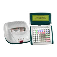
ELCOM Euro-2500 Series Service Manual (100 pages)
Brand: ELCOM
|
Category: Touch terminals
|
Size: 11 MB
Table of Contents
Advertisement

ELCOM Euro-2500 Series Service Manual (100 pages)
Brand: ELCOM
|
Category: Cash Register
|
Size: 10 MB