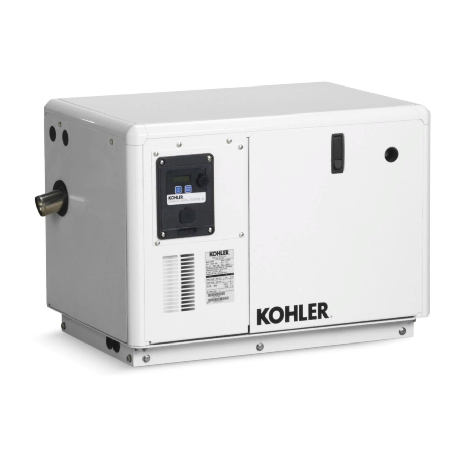
Kohler 6EKOD Installation Instructions Manual
Hide thumbs
Also See for 6EKOD:
- Service manual (120 pages) ,
- Operation manual (80 pages) ,
- Installation manual (56 pages)
Advertisement
Original Issue Date: 4/12
Model: 6EKOD/5EFKOD and 9- -11EKOZD/7- -9EFKOZD Generator Sets
Market: Marine
Subject: ADC IId Controller Replacement Kit GM83745
Introduction
These instructions explain how to replace and set up the
controller on the generator set models shown in
Figure 1. Read the entire installation procedure before
beginning installation. Perform the steps in the order
shown. The controller is shown in Figure 2.
Generator Set Model
6EKOD
5EFKOD
9EKOZD
7EFKOZD
11EKOZD
9EFKOZD
Figure 1 Generator Set Models and Controllers
1
5
4
1. LCD display
2. Pushbutton/rotary selector dial
3. Engine start/stop button
4. Power button
5. LED status indicator
Figure 2 ADC IId Controller
A Note about Controller Setup
After replacing the controller, the installer must set the
controller parameters. On the ADC IId controller, the
installer can use the key sequence described in these
instructions. Use the pushbutton/rotary selector dial to
navigate to the respective menus.
INSTALLATION INSTRUCTIONS
Controller
Kit Number
ADC IId
GM83745
2
3
GM58225A
Menus displaying the # symbol represent one of the
following data types:
System-calculated data
D
System-measured data
D
User-entered data
D
Note: The examples given on the following pages
represent digital displays with the Measurement
Units set to English.
Note: Some generator set problems can be caused by
incorrect controller settings.
settings are correct.
Parts List
ADC IId Replacement Controller
Kit: GM83745
Qty. Description
1
Controller, ADC IId
1
Instructions
Safety Precautions
Observe the following safety precautions while installing
the kit.
WARNING
Accidental starting.
Can cause severe injury or death.
Disconnect the battery cables before
working
on
Remove the negative (--) lead first
when disconnecting the battery.
Reconnect the negative (--) lead last
when reconnecting the battery.
TT-1583
9/13a
Verify that the
Part Number
GM82832
TT-1583
the
generator
set.
Advertisement
Table of Contents

Summary of Contents for Kohler 6EKOD
- Page 1 TT-1583 9/13a INSTALLATION INSTRUCTIONS Original Issue Date: 4/12 Model: 6EKOD/5EFKOD and 9- -11EKOZD/7- -9EFKOZD Generator Sets Market: Marine Subject: ADC IId Controller Replacement Kit GM83745 Introduction Menus displaying the # symbol represent one of the following data types: These instructions explain how to replace and set up the...
-
Page 2: Installation Procedure
Disabling the generator set. Accidental starting can cause severe injury or death. Before working on the generator set or connected equipment, disable the generator set as follows: (1) Move the generator set master switch to the OFF position. (2) Disconnect the power to the battery charger. (3) Remove the battery cables, negative (--) lead first. -
Page 3: Engine Metering
1.10.1 Overview Overview (Fixed Display) Overview ----> ### V ##.# Hz Displays basic and commonly sought after information ##.# hr about the generator set. This information scrolls automatically after about 5 minutes of no user input English Display ###_F ###% (pushbutton/rotary selector dial or button activity). -
Page 4: Generator Metering (And Calibration)
1.10.3 Generator Metering (and Momentarily press the pushbutton/rotary selector dial. Stop the generator set if not already done. Calibration) Displays generator output data including line-to-line and Generator Metering line-to-neutral voltages and frequency. The menu displays three-phase voltage readings when applicable. Generating---->... -
Page 5: Genset Information
1.10.4 GenSet Information Display for Measurement System is user selectable as English or Metric. Displays generator set and controller information. Displayed data is factory entered. Contrast display is user adjustable to help improve digital display visibility in dimly lit rooms or in direct sunlight. -
Page 6: Voltage Regulator
1.15.1 Voltage Regulator push and hold the pushbutton/rotary selector dial until the Editing Enabled popup appears. Editing of the Displays the voltage regulator adjustment, volt/Hz, gain, voltage adjustment is now available. and stability adjustment values. The user can change the individual value or can select The voltage regulator value is reviewable at all times Reset VR?- -Yes to reset to the default value. -
Page 7: Prime Menu
1.15.3 Prime Menu Volt Select Volt Select: ----> 120/240 V 1 Ph This menu, if confirmed, allows the user to initiate the ###/### V # Ph electric fuel pump to prime the fuel system. Prime the Fuel System 120/208 V 3 Ph Push To Prime ---->... -
Page 8: Usb Flowchart
PUSH TO LOAD Complete Rotate Knob Note: Before inserting a mass-storage device (USB CustomUSB host connector), power off and then power on the (Kohler Power Systems 2-GB “spin” full size controller. Part Number KW-A202) Imation 4-GB full size See Figure 5 for tested/approved manufacturer’s USB Lexar... - Page 9 GM79008-C Figure 6 Wiring Diagram (Point-to-Point) TT-1583 9/13...
- Page 10 Notes TT-1583 9/13...
- Page 11 Notes TT-1583 9/13...
- Page 12 Singapore 619159 KOHLERPower.com Phone (65) 6264-6422, Fax (65) 6264-6455 Availability is subject to change without notice. Kohler Co. reserves the right to change the design or specifications without notice and without any obligation or liability whatsoever. Contact your local Kohlerr generator set distributor for availability.


Need help?
Do you have a question about the 6EKOD and is the answer not in the manual?
Questions and answers