
Related Manuals for Det-Tronics X Series


Summary of Contents for Det-Tronics X Series
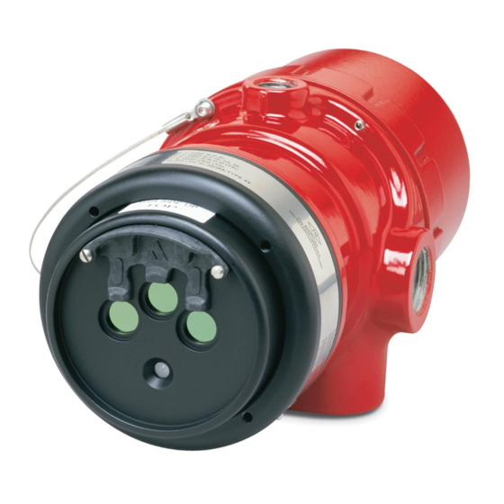
- Page 1 Instructions Enhanced Flame Inspector Software for use with Det-Tronics X-Series Flame Detectors 95-8751...
-
Page 2: Table Of Contents
Table Of Contents DESCRIPTION . . . . . . . . . . . . . . . . . . . . . . . . . . . . . . . . . . . . . . . . . . . . . . 1 FEATURES . -
Page 3: Description
Enhanced Flame Inspector software, with the exception of the Hangar Mode on the X3301. DESCRIPTION HARDWARE REQUIREMENTS Det-Tronics X-Series Flame Detectors record pertinent Enhanced Flame Inspector software is designed for configuration and event information in the device’s non- PCs using the Windows operating system. - Page 4 NOTE CONNECT THIS END TO The PC must always be located in a non- THE SENSOR MODULE. hazardous controlled location. Modbus communications are only available on X-series detectors that have Relay, Relay/4-20mA, and Pulse outputs. Modbus communications are not available on X-series detectors that have HART or EQP outputs.
-
Page 5: Software
SOFTWARE not established (the face of the detector has not appeared The Enhanced Flame Inspector software can be run on the screen), check for the following conditions: directly from the CD drive or it can be installed onto the hard drive. To install the software onto the hard drive, •... - Page 6 Reduced Oi Advisory, formerly called Bin Disable, can now be indicated on the status LED, 4-20mA output (6mA) or via the AUX relay, if con gured. This The Fire B (Flash Fire) Algorithm status condition is active when one or more of the sensor returns less than can be disabled.
- Page 7 When Cancel and Save appear here this indicates a change was made to the detector’s con guration. If the change is not saved the detector will not retain the new con guration. A yellow box with a red check indicates this con guration setting has been changed.
- Page 8 Device Status Options Description Normal Power is applied and no faults are occurring. Fire Alarm A fire condition has been detected. This indicator also turns on to signal a successful manual o i test. Fire A, B,C, D, E See X3301/X3302 Event Log Descriptions section (page 13). Warm Up Detector is in the power-up time delay mode.
- Page 9 Device Status Options Description Normal Power is applied and no faults are occurring. Quick Alarm Quick fire alarm signal generated. UV Pre-Alarm UV sensor in pre-alarm condition. UV Alarm UV sensor generating fire alarm signal. Manual UV Active Manual o i test on UV sensor in progress. Auto UV Active Automatic o i test on UV sensor in progress.
-
Page 10: Determining Detector Configuration And Programming
DETERMINING DETECTOR – via an external switch (refer to detector manual for CONFIGURATION AND proper wiring). PROGRAMMING – by Enhanced Flame Inspector software. To determine the current settings for the detector, click NOTE on the “Configuration” tab. The Configuration window is If the sensor module is removed from the detector displayed (see Figures 6-7). -
Page 11: Manual O I Test Initiated By Enhanced Flame Inspector
At the detector: At the PC: Fault Relay becomes de-energized. Fire Alarm indicator turns on (red). LED turns amber. The 4-20 mA indicator reads 20 mA. At the detector: 6. Remove the magnet or release the test switch. The Fire Alarm Relay changes state. Manual o i Active indicator turns off, and the Manual The 4-20 mA output goes to 20 mA. - Page 12 Press to perform an active manual o i test. Fire alarm relay and 4-20 mA output will be activated. Press to perform a passive manual o i test. Fire alarm relay and 4-20 mA output will not be activated. Press to initiate o i calibration. Current output will be driven to the value selected here.
-
Page 13: O I Calibration
4-20 mA TEST / CALIBRATION CALIBRATION The 4-20 mA output will be driven to the output selected 1. Clean the detector viewing windows by following the from the pull-down menu on the Control window. At this cleaning procedure described in the “Maintenance” time the detector will go into a fault condition and the fire section of the detector instruction manual. -
Page 14: Monitoring The Detector's Event Logs
MONITORING THE SORT ORDER DETECTOR’S EVENT LOGS Events will be sorted by time as a default. To sort events by any other column, click the column you want the Click on the Read Logs button (No logs are displayed prior events sorted by. - Page 15 X3301/X3302 EVENT LOG DESCRIPTIONS Event Description Status Condition ASCII Mode Unit changed to ASCII communication protocol Calibration 4-20 mA A 4-20mA output calibration was initiated Configuration Changed Configuration changes were made. Delayed Fire Sustained Fire Mode. Sustained fire requirements have been met. Detection Cycle Complete Persistent or Automotive fire cycle completed.
- Page 16 X2200/X9800/X5200 EVENT LOG DESCRIPTIONS Event Description Status Condition Adjust 4-20mA Output The 4-20mA output was adjusted. Aux Relay Active The auxiliary relay has been activated. RTC Reset The Real Time Clock was changed. Fire Alarm Fire alarm is active. *CLR:Fire Alarm Fire alarm has cleared.
-
Page 17: Troubleshooting
X3301/X3302 EVENT LOG DESCRIPTIONS AND TROUBLESHOOTING Event Description Status Condition Recommended Action IR levels have caused the detection distance Check detector field of view, re-aim if needed. Addition of FOV Background IR Fault to diminish by at least 50% sight limited may be required. Check sensitivity setting. Check detector field of view for IR source, re-aim if needed. - Page 18 X2200/X5200/X9800 EVENT LOG DESCRIPTIONS AND TROUBLESHOOTING Event Description Status Condition Recommended Action IR levels have caused IR detection range to Check detector field of view for IR sources, re-aim if Background IR Fault reduce by more than 50%. needed. Check sensitivity setting. UV levels have caused UV detection range Check detector field of view for UV sources, re-aim if Background UV Fault...
-
Page 19: Replacement Parts
Check with your Local Authority Minneapolis, Minnesota 55438 USA or the local Detector Electronics office for recycling Main: (952) 941-5665 or (800) 765-FIRE advice. Customer Service: (952) 946-6491 Fax: (952) 829-8750 Web site: www.det-tronics.com E-mail: det-tronics@det-tronics.com 95-8751... - Page 20 © 2019 Detector Electronics Corporation . All rights reserved . Toll-free: 800 .765 .3473 6901 West 110 Street Fax: 952 .829 .8750 Minneapolis, MN 55438 USA Det-Tronics manufacturing system is certified to ISO 9001— det-tronics@det-tronics .com the world’s most recognized quality management standard . www.det-tronics.com...
Need help?
Do you have a question about the X Series and is the answer not in the manual?
Questions and answers