Det-Tronics Protect-IR X3301 Instructions Manual
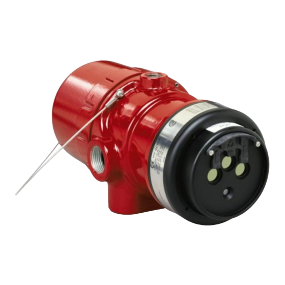
Multispectrum ir flame detector
Hide thumbs
Also See for Protect-IR X3301:
- Instructions manual (43 pages) ,
- Addendum (21 pages) ,
- Instructions manual (20 pages)
Table of Contents

Related Manuals for Det-Tronics Protect-IR X3301


Summary of Contents for Det-Tronics Protect-IR X3301
- Page 1 Instructions 95-8527 Protect•IR ® Multispectrum IR Flame Detector X3301 Detector Electronics Corporation 6901 West 110th Street • Minneapolis, Minnesota 55438 USA 9/03 95-8527 Tel: 952.941.5665 or 800.765.3473 • Fax: 952.829.8750...
-
Page 2: Table Of Contents
Table Of Contents DESCRIPTION ....................1 Outputs ....................1 LED .......................2 Optical Integrity (Oi) ................2 Communication ..................3 Data Logging..................3 Integral Wiring Compartment ..............3 GENERAL APPLICATION INFORMATION ..........3 Response Characteristics ..............3 Important Application Considerations ...........3 IMPORTANT SAFETY NOTES ..............4 INSTALLATION....................4 Detector Positioning................4 Detector Orientation................5 Protection Against Moisture Damage ...........5 Wiring Procedure ..................5 Setting Device Network Addresses (EQP Model Only) ......12... -
Page 3: Description
TRONICS ® INSTRUCTIONS Protect•IR ® Multispectrum IR Flame Detector X3301 IMPORTANT Be sure to read and understand the entire instruction manual before installing or operating the flame detection system. Any deviation from the recommendations in this manual may impair system performance and compromise safety. ATTENTION The X3301 includes the Automatic Optical Integrity (o i ) feature —... -
Page 4: Led
(no fault or fire alarm) The EQP model is designed for use exclusively with Fault Amber the Det-Tronics Eagle Quantum Premier system. The Fire (Alarm) detector communicates with the system controller over a digital communication network or LON/SLC (Local Medium Sensitivity... -
Page 5: Communication
The magnetic o i test is performed by placing a magnet GENERAL APPLICATION by the marked location (mag o i ) on the outside of the INFORMATION detector. The manual o i test is accomplished by connecting the o i lead (terminal 22) to power supply RESPONSE CHARACTERISTICS minus via an external switch. -
Page 6: Important Safety Notes
IMPORTANT SAFETY NOTES INSTALLATION WARNING DETECTOR POSITIONING Do not open the detector assembly in a hazardous area when power is applied. The detector contains Detectors should be positioned to provide the best limited serviceable components and should never unobstructed view of the area to be protected. The be opened. -
Page 7: Detector Orientation
If conduit is used, drains must be installed at water collection points to automatically drain accumulated Oi PLATE moisture. Conduit breathers should be installed at upper locations to provide ventilation and allow water PLACE MAGNET vapor to escape. At least one breather should be used HERE TO INITIATE MAGNETIC Oi with each drain. - Page 8 Relay and 4-20 mA Output Models EOL Resistors (Not Used with EQP Model) Follow the instructions below to install the X3301. To ensure that the insulating material of the wiring terminal block will not be affected by the heat generated 1.
- Page 9 Figure 4—X3301 Terminal Block 4-20 mA + SPARE 4-20 mA – 4-20 mA + REF 4-20 mA – REF SPARE COM FIRE COM FIRE COM AUX N.O. FIRE N.O. FIRE N.O. AUX N.C. FIRE N.C. FIRE N.C. AUX COM FAULT COM FAULT RS-485 A N.O.
- Page 10 X3301 DETECTOR FIRE ALARM PANEL 4-20 mA + 4-20 mA – SPARE 4-20 mA + REF 4-20 mA – REF SPARE COM FIRE 2 COM AUX COM FIRE N.O. FIRE 2 N.O. AUX N.O. FIRE E.O.L. DEVICE 4 N.C. FIRE 2 N.C.
- Page 11 X3301 IR DETECTOR X3301 IR DETECTOR 4-20 mA + 4-20 mA – 4-20 mA + 875 Ω MAX 4-20 mA – 875 Ω MAX AT 24 VDC AT 24 VDC 4-20 mA – REF 4-20 mA + REF – – 4 TO 20 MA 4 TO 20 MA 24 VDC...
- Page 12 EQP Model 5. Check all field wiring to be sure that the proper connections have been made. 1. Connect external wires to the appropriate terminals inside the device junction box. (See 6. Replace the device cover. Figure 13 for terminal identification.) 7.
- Page 13 CH 1 CH 2 CH 3 CH 4 CH 5 CH 6 CH 7 CH 8 RELAY 2 RELAY 3 RELAY 4 RELAY 1 DIGITAL INPUTS RELAY 5 RELAY 6 RELAY 7 RELAY 8 95-8527...
-
Page 14: Setting Device Network Addresses (Eqp Model Only)
ADDRESS SWITCHES SENSOR MODULE REMOVED FROM HOUSING A2191 Figure 15—Location of Address Switches SETTING DEVICE NETWORK ADDRESSES disassembly of the device. Always observe (EQP Model Only) precautions for handling electrostatic sensitive devices. Overview of Network Addresses The address number is binary encoded with each Each device on the LON must be assigned a unique switch having a specific binary value with switch 1 address. -
Page 15: Startup Procedure
5. Verify that all detectors in the system are properly aimed at the area to be protected. (The Det-Tronics 6. If all wiring checks out and cleaning of the o i Q1201C Laser Aimer is recommended for this plate/window did not correct the fault condition, purpose.) -
Page 16: Cleaning Procedure
Disable any extinguishing equipment that is connected to the unit to prevent unwanted actuation. To clean the windows and o i plate, use Det-Tronics NOTE window cleaner (part number 001680-001) and a soft If the o i plate is removed, be sure to install the cloth, cotton swab or tissue and refer to the following original o i plate. -
Page 17: Features
FEATURES POWER UP TIME— Fault indication clears after 0.5 second; device is ready • Long detection range to carbonaceous fires. to indicate an alarm condition after 30 seconds. • Unequaled false alarm rejection. OUTPUT RELAYS— • Responds to a fire in the presence of modulated Fire Alarm relay, Form C, 5 amperes at 30 vdc: blackbody radiation (i.e. - Page 18 ENCLOSURE MATERIAL— Increased Safety Model Copper-free aluminum (red-painted) or 316 stainless 0539 II 2 GD steel. EEx de IIC T5–T6 DEMKO 01 ATEX 130204 T6 (T = –55°C to +60°C). VIBRATION— Conformance per FM 3260: 2000, MIL-STD 810C (Curve T5 (T = –55°C to +75°C).
-
Page 19: Replacement Parts
REPLACEMENT PARTS ORDERING INFORMATION The detector is not designed to be repaired in the field. When ordering, please specify: If a problem should develop, refer to the Troubleshooting section. If it is determined that the X3301 IR Flame Detector problem is caused by an electronic defect, the device must be returned to the factory for repair. - Page 20 APPENDIX A FM Approvals Description and Performance Report THE FOLLOWING ITEMS, FUNCTIONS AND OPTIONS DESCRIBE THE FM APPROVAL: • Explosion-proof for Class I, Div. 1, Groups B, C and D Hazardous (Classified) Locations per FM 3615. • Dust-ignition proof for Class II/III, Div. 1, Groups E, F and G Hazardous (Classified) Locations per FM 3615. •...
- Page 21 FM Approvals Description and Performance Report – Continued RESPONSE CHARACTERISTICS: Very High Sensitivity Fuel Size Distance Average Response Time (feet) (seconds)*** n-Heptane 1 x 1 foot 210* n-Heptane** 1 x 1 foot 210* n-Heptane 1 x 1 foot n-Heptane 6 in. x 6 in. Isopropanol 6 in.
- Page 22 FM Approvals Description and Performance Report – Continued RESPONSE CHARACTERISTICS IN THE PRESENCE OF FALSE ALARM SOURCES: Very High Sensitivity False Alarm Source Distance Fire Source Distance Average Response Time (feet) (feet) (seconds)*** Sunlight, direct, modulated, reflected — 6-inch propane <...
- Page 23 FM Approvals Description and Performance Report – Continued FALSE ALARM IMMUNITY: Very High Sensitivity False Alarm Source Distance Modulated Response Unmodulated Response (feet) Sunlight, direct, reflected — No alarm No alarm Vibration No alarm Radio frequency interference No alarm (keyed) No alarm (steady) Arc welding No alarm...
- Page 24 FM Approvals Description and Performance Report – Continued FIELD OF VIEW: Very High Sensitivity Fuel Size Distance Horizontal Avg. Horiz. Response Time Vertical Avg. Vert. Response Time (feet) (degrees) (seconds)*** (degrees) (seconds)*** n-Heptane 1 x 1 foot 150* –45 –30 n-Heptane 1 x 1 foot –45...
- Page 25 FM Approvals Description and Performance Report – Continued Medium Sensitivity Fuel Size Distance Horizontal Avg. Horiz. Response Time Vertical Avg. Vert. Response Time (feet) (degrees) (seconds)*** (degrees) (seconds)*** n-Heptane 1 x 1 foot –45 –30 n-Heptane 1 x 1 foot –45 –30 Diesel**...
- Page 26 FM Approvals Description and Performance Report – Continued 0° 0° 15° 15° 70 ft 15° 15° 80 ft 30° 30° 30° 30° 60 ft 70 ft 45° 60 ft 45° 45° 45° 50 ft 50 ft 40 ft 40 ft 30 ft 20 ft 20 ft...
- Page 27 FM Approvals Description and Performance Report – Continued 0° 0° 15° 15° 15° 15° 210 ft 100 ft 30° 30° 30° 30° 90 ft 180 ft 80 ft 45° 45° 45° 45° 150 ft 70 ft 60 ft 120 ft 50 ft 90 ft 40 ft...
- Page 28 Printed in USA Detector Electronics Corporation 6901 West 110th Street • Minneapolis, Minnesota 55438 USA Tel: 952.941.5665 or 800.765.3473 • Fax: 952.829.8750...
Need help?
Do you have a question about the Protect-IR X3301 and is the answer not in the manual?
Questions and answers