Det-Tronics X3302 Instructions Manual
Multispectrum ir flame detector
Hide thumbs
Also See for X3302:
- Instructions manual (36 pages) ,
- Addendum (16 pages) ,
- Instructions manual (20 pages)
Table of Contents
Advertisement
Quick Links
Advertisement
Table of Contents

Related Manuals for Det-Tronics X3302


Summary of Contents for Det-Tronics X3302
- Page 1 Instructions Multispectrum IR Flame Detector X3302 95-8768...
-
Page 2: Table Of Contents
Response Characteristics . . . . . . . . . . . . . . 4 X3302 Model Matrix . . . . . . . . . . . . . . . . . 19 Important Application Considerations . -
Page 3: Description
Carbon Dioxide (CO 2 ) in alarm or fault conditions. the combustion process. The detection capability of the X3302 is double that of traditional UV and Microprocessor controlled heated optics increase UVIR detectors. At the same time, it attains solar resistance to moisture and ice. -
Page 4: Outputs
(OPTICAL INTEGRITY) always follows the status of the relays. Automatic o i The X3302 includes the Automatic o i feature — a calibrated performance test that is automatically Table 1—Detector Status Conditions Indicated by Current Level performed once per minute to verify complete Current Level (±0.3 mA) -
Page 5: Communication
The X3302 signals a fault condition when less for communicating status and other information than half of the detection range remains. This is with external devices. The RS-485 supports indicated by the Fault output and is evident by the Modbus protocol, with the detector configured as yellow color of the LED on the face of the detector. -
Page 6: General Application Information
(paint, oil, etc.) that will burn and possibly considerations need to be given in these situations. cause the X3302 to alarm. Due to the possibility of an alarm condition, arc welding should not be performed The detector differentiates fire from non-fire sources within 40 feet (12.2 m) of the detector configured to... -
Page 7: Important Safety Notes
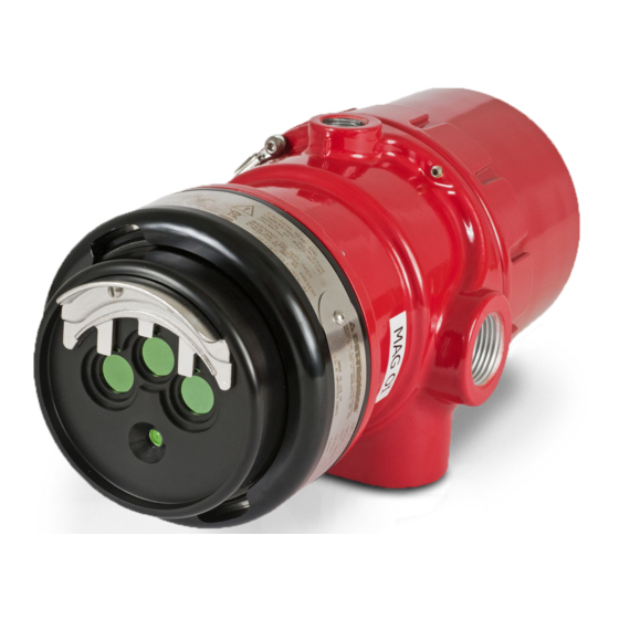
MAGNET CENTER AXIS OF DETECTOR FIELD OF VIEW F2068 CORRECT DETECTOR D1974 STATUS INDICATOR NOTE: DETECTOR MUST ALWAYS BE AIMED DOWNWARD AT LEAST 10 TO 20 DEGREES. Figure 1—Detector Orientation Relative to Horizon Figure 2—Front View of the X3302 95-8768... -
Page 8: Detector Orientation
Refer to Figure 2 and ensure that the o i reflector with explosion-proof installation requirements, but plate will be oriented as shown when the X3302 are highly recommended to prevent water ingress is installed and sighted. This will ensure proper in outdoor applications. - Page 9 1/2 inch (12 mm). A minimum Relay and 0–20 mA Output Models input voltage of 18 Vdc must be present at the X3302. Follow the instructions below to install the X3302. NOTE Make field connections following local Refer to “Power Consumption” in the ordinances and guidelines in this manual.
- Page 10 +Vin +Vin MAN O i BULKHEAD –Vin –Vin –Vin D2061 Figure 6—Resistor Installation (For Ex d Wiring only) Figure 5—X3302 Wiring Terminal Identification X3302 DETECTOR FIRE ALARM PANEL mA + mA – SPARE mA + REF mA – REF SPARE COM FIRE 2...
- Page 11 X3302 DETECTOR FIRE ALARM PANEL mA + mA – SPARE SHIELD mA + REF mA – REF SPARE COM FIRE 2 COM AUX COM FIRE NO FIRE 2 NO AUX NO FIRE NC FIRE 2 FAULT 4 NC AUX NC FIRE...
- Page 12 –Vin –Vin –Vin –Vin O i TEST 1 O i TEST 1 Figure 10—X3302 Detector Wired for Non-Isolated 0 to 20 mA Figure 11—X3302 Detector Wired for Non-Isolated 0 to 20 mA Current Output (Sourcing) Current Output (Sinking) 24 VDC 24 VDC –...
- Page 13 CH 1 CH 2 CH 3 CH 4 CH 5 CH 6 CH 7 CH 8 RELAY 2 RELAY 3 RELAY 4 RELAY 1 DIGITAL INPUTS RELAY 5 RELAY 6 RELAY 7 RELAY 8 95-8768...
-
Page 14: Setting Device Network Addresses
COM 1 A COM 2 A COM 1 B COM 2 B POWER SHIELD POWER SHIELD +Vin +Vin A2191 –Vin –Vin B2089 — — Figure 17 Location of Address Switches Figure 16 Wiring Terminal Identification for X3302 EQP Model 95-8768... -
Page 15: Startup Procedure
When installation of the equipment is complete, The use of the Enhanced Flame Inspector perform the “Fire Alarm Test” below. cable and software from Det-Tronics can be considered to determine the nature of the fault FIRE ALARM TEST condition. Refer to instruction manual 95-8751 Disable any extinguishing equipment that is for more information. -
Page 16: Maintenance
To maintain maximum sensitivity and false Install the new (or cleaned) o i reflector plate. alarm resistance, the viewing windows of the X3302 must be kept relatively clean. Refer to the NOTE following procedure for cleaning instructions. When installing the stainless steel o i... -
Page 17: Periodic Checkout Procedure
These plates are not interchangeable. Order the replacement • Operates under adverse weather conditions that matches the o i reflector plate on your X3302 and in dirty environments Flame Detector. • Mounting arm allows easy sighting •... -
Page 18: Specifications
The Fault relay has redundant terminals and RESPONSE TIME— normally open contacts, normally energized Typical response times are under 10 seconds. operation, and latching or non-latching operation. DIMENSIONS— See Figure 20. (11.9) 10.0 (25.4) (12.2) B2067 — Figure 20 X3302 Dimensions in Inches (cm) 95-8768... -
Page 19: Replacement Parts
(5 Stainless Steel Reflector Plates) with Inspector Connector and Monitor –10°C (14°F) and above +60°C (140°F) use field wiring suitable for both minimum and maximum Replacement o i Reflector Plate for X3302 with 007307-003 Black plate (requires Inspector Connector to ambient temperature. -
Page 20: Ordering Information
ORDERING INFORMATION When ordering, please specify: X3302 Multispectrum IR Flame Detector Refer to the X3302 Model Matrix for details Q9033 Mounting Arm is required: – Q9033A for aluminum detectors only – Q9033B for aluminum and stainless steel detectors ACCESSORIES Part Number... -
Page 21: X3302 Model Matrix
X3302 MODEL MATRIX MODEL DESCRIPTION X3302 Multispectrum IR Flame Detector TYPE MATERIAL Aluminum Stainless Steel (316) TYPE THREAD TYPE 4 Port, Metric M25 4 Port, 3/4" NPT TYPE OUTPUTS Relay Relay and 0-20 mA Eagle Quantum Premier (EQP) Relay and Pulse... - Page 22 HIGH RESOLUTION FIELD OF VIEW The following high resolution field of view diagrams depict the detectors horizontal and vertical response to various fires. Note that the response distance indicated in each diagram differs between fuel type, fire size, and the sensitivity configuration of the flame detector. 0°...
- Page 23 0° 15° 15° 110 (33.5) 15° 15° 52.5 (16) 100 (30.5) 30° 30° 50 (15.2) 30° 30° 90 (27.4) 45 (13.7) 80 (24.4) 45° 45° 40 (12.2) 45° 45° 70 (21.3) 35 (10.7) 60 (18.3) 30 (9.1) 50 (15.2) 25 (7.6) 40 (12.2) 20 (6.1) 30 (9.1)
- Page 24 0° 0° 15° 15° 15° 15° 70 (21.3) 35 (10.7) 30° 30° 30° 30° 60 (18.3) 30 (9.1) 45° 45° 45° 45° 50 (15.2) 25 (7.6) 40 (12.2) 20 (6.1) 30 (9.1) 15 (4.6) 10 (3) 20 (6.1) 5 (1.5) 10 (3) 5 (1.5) 10 (3)
- Page 25 0° 0° 15° 15° 15° 15° 35 (10.7) 17.5 (5.3) 30° 30° 30° 30° 30 (9.1) 15 (4.6) 45° 45° 45° 45° 25 (7.6) 20 (6.1) 10 (3) 15 (4.6) 5 (1.5) 10 (3) 5 (1.5) 5 (1.5) 10 (3) 5 (1.5) 15 (4.6) 20 (6.1)
-
Page 26: Performance Report
EOL resistors must be ceramic, wirewound type, rated 5 watts minimum, with actual power dissipation not to exceed 2.5 watts. • The Multispectrum infrared (IR) flame detector type X3302 is to be installed in places where there is a low risk of mechanical damage. •... - Page 27 FM Approval and Performance Report – Continued MANUAL OPTICAL INTEGRITY TEST: The Manual / Magnetic o i performs the same calibrated test as the Automatic o i , and additionally actuates the alarm relay to verify output operation. If there is a 50% loss of its detection range, an alarm signal is not generated.
- Page 28 Medium Sensitivity Distance Average Response Time Fuel Size/Flow Rate feet (m) (seconds)** Hydrogen 30 inch plume/100 SLPM* 70 (21.3) Methanol 1 x 1 foot 35 (10.7) Syngas*** 30 inch plume/120 SLPM* 50 (15.2) Methane 30 inch plume/40 SLPM* 30 (9.1) * Standard Liters Per Minute (Standard conditions defined as +25°C and 14.696 PSIA).
- Page 29 FM Approval and Performance Report – Continued FIELD OF VIEW Very High Sensitivity Horiz. Average Vert. Average Size/ Distance Horizontal Vertical Fuel Response Time Response Time Flow Rate feet (m) (degrees) (degrees) (seconds)** (seconds)** 30 inch plume/ Hydrogen 100 (30.5) 100 SLPM* Methanol 1 x 1 foot...
- Page 30 FM Approval and Performance Report – Continued Medium Sensitivity Horiz. Average Vert. Average Size/ Distance Horizontal Vertical Fuel Response Time Response Time Flow Rate feet (m) (degrees) (degrees) (seconds)** (seconds)** 30 inch plume/ Hydrogen 50 (15.2) 100 SLPM* Methanol 1 x 1 foot 35 (10.7) 30 inch plume/ Syngas***...
- Page 31 RESPONSE CHARACTERISTICS IN THE PRESENCE OF FALSE ALARM SOURCES Very High Sensitivity Distance Average Fire source and size/ Distance to False Alarm Source to source Response time flow rate fire feet (m) feet (m) (seconds)** Sunlight, direct, unmodulated* — Hydrogen @ 100 SLPM 125 (38.1) Sunlight, direct, modulated* —...
- Page 32 Medium Sensitivity Average Distance to Fire source and size/ Distance to False Alarm Source Response time source feet (m) flow rate fire feet (m) (seconds)** Sunlight, direct, unmodulated* — Hydrogen @ 100 SLPM 70 (21.3) Sunlight, direct, modulated* — Hydrogen @ 100 SLPM 10 (3.0) Sunlight, reflected, unmodulated* —...
-
Page 33: Appendix Bcsa Approval
APPENDIX B CSA APPROVAL Multispectrum IR Flame Detector/Controller X3302 Series, rated 18-30 Vdc, 4.6 Watts to 17 Watts. Relay contacts rated 30 Vdc, 5 Amps. DIVISION CLASSIFICATION: CLASS 4818 04 - SIGNAL APPLIANCES - Systems - For Hazardous Locations Class I, Division 1, Groups B, C, and D (T4A); Class II, Division 1, Groups E, F, and G (T4A);... -
Page 34: Appendix Catex Approval
Each resistor may dissipate a maximum of 5 watts and must be rated appropriately for the application. The Multispectrum infrared (IR) flame detector type X3302 is to be installed in places where there is a low risk of mechanical damage. - Page 35 The following accessories are ATEX approved for use with the X3302 Flame Detector: Part Number Description 007290-001 Q9033B Stainless Steel Mounting Arm Assembly is for aluminum and stainless steel detectors 007290-002 Q9033A Aluminum Mounting Arm Assembly is for aluminum detectors only...
-
Page 36: Appendix Diecex Approval
Each resistor may dissipate a maximum of 5 watts and must be rated appropriately for the application. The Multispectrum infrared (IR) flame detector type X3302 is to be installed in places where there is a low risk of mechanical damage. -
Page 37: Appendix Eadditional Approvals
ADDITIONAL APPROVALS SIL 2 IEC 61508 Certified SIL 2 Capable. Applies to specific models – refer to the SIL 2 Certified X3302 Safety manual (95-8720 ) for details. BRAZIL UL-BR 12.0093X Ex db eb IIC T6...T5 Ex tb IIIC T130°C T6 (Tamb = –50°C to +60°C) -
Page 38: Conformity
APPENDIX F DECLARATION OF CONFORMITY EU Declaration of Conformity Model X3302 (Multispectrum Infrared Flame Detector) 014052-XXX, 022XXX-XXX, 028XXX-XXX, 029XXX-XXX The object of the declaration described above is in conformity with the relevant Union harmonisation legislation: ATEX Directive: 2014/34/EU EN 60079-0:2012+A11:2013 Certificate No.: DEMKO 01 ATEX 130204X... - Page 39 © 2019 Detector Electronics Corporation . All rights reserved . Toll-free: 800 .765 .3473 6901 West 110 Street Det-Tronics manufacturing system is certified to ISO 9001— Fax: 952 .829 .8750 Minneapolis, MN 55438 USA the world’s most recognized quality management standard .
Need help?
Do you have a question about the X3302 and is the answer not in the manual?
Questions and answers