Det-Tronics X5200 Instructions Manual
Uvir flame detector
Hide thumbs
Also See for X5200:
- Instructions manual (35 pages) ,
- Addendum (21 pages) ,
- Instructions manual (20 pages)
Table of Contents
Advertisement
Quick Links
Advertisement
Table of Contents

Related Manuals for Det-Tronics X5200


Summary of Contents for Det-Tronics X5200
- Page 1 Instructions 95-8546 UVIR Flame Detector X5200 Rev: 6/10 95-8546...
-
Page 2: Table Of Contents
Table of Contents Description . . . . . . . . . . . . . . . . . . . . . . . . . . . . . . 1 troUbLeshooting . -
Page 3: Description
DESCRIPTION The evolution continues with the new X5200 UVIR A multi-color LED on the detector faceplate indicates Flame Detector. The X5200 meets the most stringent detector status condition. -
Page 4: Led
High UV Sensitivity Three Red Flashes X5200. Therefore, an open circuit on the loop will Very High UV Sensitivity Four Red Flashes not cause the fault relay to change state or the detector status LED to indicate a fault. -
Page 5: Communication
The X5200 signals a fault condition when less than half DAtA LOGGING / EvENt MONItORING of the detection range remains. This is indicated by the Data logging for event monitoring capability is also Fault relay and is evident by the yellow color of the LED provided. -
Page 6: Uv Detector Options
X5200. Welding rods with clay binders – Standard Signal Processing. do not burn and will not be detected by the X5200. However, system bypass is always recommended, since the material being welded may be contaminated with Arc Rejection (Recommended Factory setting) organic substances (paint, oil, etc.) that will burn and... -
Page 7: False Alarm Sources
FALsE ALARM sOuRCEs FACtORs INHIbItING DEtECtOR REspONsE uv: The UV sensor is solar blind to the ultraviolet windows component of solar radiation. However, it will Glass and Plexiglas windows significantly attenuate respond to sources of UV besides fire, such as radiation and must not be located between the detector electric arc welding, lightning, high voltage corona, and a potential flame source. -
Page 8: Important Safety Notes
ImPORTaNT SafETy NOTES Table 3 uv and IR Absorbing Gases and vapors WarnIng Do not open the detector assembly in a hazardous The following is a partial list of compounds that exhibit area when power is applied. The detector contains significant UV absorption characteristics. -
Page 9: Installation
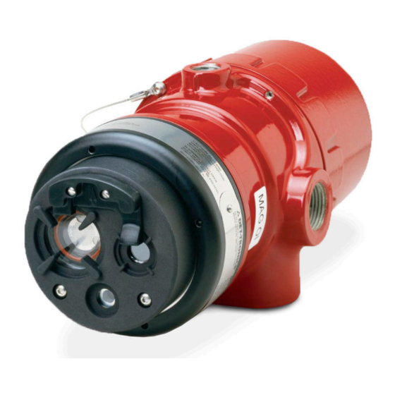
UV VIEWING WINDOW DEtECtOR ORIENtAtION MAGNET Refer to Figure 2 and ensure that the o i plate will be oriented as shown when the X5200 is mounted DETECTOR STATUS INDICATOR A2134 and sighted. This will ensure proper operation of the o i system and will also minimize the accumulation of Figure 2—Front View of the X5200... -
Page 10: Wiring Procedure
) or 16 AWG for dimensions. (1.31 mm ) shielded cable is recommended. Wires should be stripped 3/8 inch (9 mm). A minimum input voltage of 18 Vdc must be present at the X5200. (10.2) 4X ø0.42 13.1 (1.1) (33.4) (7.6) -
Page 11: Eol Resistors
EOL REsIstORs (Not used with EQp Model) To ensure that the insulating material of the wiring terminal Follow the instructions below to install the X5200. block will not be affected by the heat generated by EOL resistors, observe the following guidelines when installing Make field connections following local ordinances the resistors. - Page 12 X5200 DETECTOR FIRE ALARM PANEL 4-20 mA + 4-20 mA – SPARE 4-20 mA + REF 4-20 mA – REF SPARE COM FIRE 2 COM AUX COM FIRE N.O. FIRE 2 N.O. AUX N.O. FIRE E.O.L. DEVICE 4 N.C. FIRE 2 N.C.
- Page 13 24 VDC – 24 VDC – O i TEST 1 O i TEST 1 Figure 10—X5200 Detector Wired for Non-Isolated 0 to 20 mA Current Figure 9—X5200 Detector Wired for Non-Isolated 0 to 20 mA Current Output (Sinking) Output (Sourcing)
- Page 14 COM SHIELD COM SHIELD COM 1 A COM 2 A COM 1 B COM 2 B POWER SHIELD POWER SHIELD 24 VDC 24 VDC – – 24 VDC 24 VDC A2089 Figure 13—Wiring Terminal Identification for X5200 EQP Model 95-8546...
- Page 15 CH 1 CH 2 CH 3 CH 4 CH 5 CH 6 CH 7 CH 8 RELAY 1 RELAY 2 RELAY 3 RELAY 4 DIGITAL INPUTS RELAY 5 RELAY 6 RELAY 7 RELAY 8 95-8546...
-
Page 16: Setting Device Network Addresses
CLOSED = ON required to gain access to the network address A2190 switches. For hazardous areas, the area must be Figure 16—Address Switches for X5200 de-classified before attempting disassembly of the device. Always observe precautions for handling electrostatic sensitive devices. -
Page 17: Startup Procedure
Verify that all detectors in the system are properly aimed at the area to be protected. (The Det-Tronics 20 mA Fire Alarm Q1201C Laser Aimer is recommended for this purpose.) 1 If fault continues, return device to factory for repair. -
Page 18: Maintenance
To maintain maximum sensitivity and false alarm interchangeable and should not be mixed with resistance, the viewing windows of the X5200 must be o i plates from other detectors. If corrosive kept relatively clean. Refer to the procedure below for contaminants in the atmosphere cause the o i cleaning instructions. -
Page 19: Features
The auxiliary relay has normally open / normally closed contacts, normally energized or de-energized AssOCIAtED MANuALs operation, and latching or non-latching operation. List of X5200 related manuals: CURRENT OUTPUT (Optional)— tItLE FORM NuMbER 0 to 20 milliampere (±0.3 mA) dc current, with a... - Page 20 ENCLOSURE MATERIAL— 100% REPRESENTS THE MAXIMUM DETECTION DISTANCE FOR A GIVEN FIRE. THE SENSITIVITY INCREASES AS THE ANGLE OF Copper-free aluminum (painted) or 316 stainless steel. INCIDENCE DECREASES. VIEWING ANGLE VIBRATION— 0∞ 15∞ 15∞ Conformance per FM 3260: 2000, MIL-STD 810C (Curve AW). 30∞...
- Page 21 They shall maintain the degree of ingress protection IP66 for the apparatus. Unused apertures shall be closed with suitable blanking elements. NOTE For ATEX installations, the X5200 detector housing must be electrically connected to earth ground. 95-8546...
-
Page 22: Replacement Parts
If a problem should develop, refer to the Troubleshooting X5200 UVIR Flame Detector section. If it is determined that the problem is caused by Refer to the X5200 Model Matrix below for details an electronic defect, the device must be returned to the factory for repair. - Page 23 X5200 MODEL MAtRIX MODEL DEsCRIptION UV/IR Flame Detector X5200 X5200M UV/IR Flame Detector with Molybdenum Tube tYpE MAtERIAL Aluminum Stainless Steel (316) tYpE tHREAD tYpE 4 PORT, METRIC M25 4 PORT, 3/4" NPT tYpE Outputs Relay Relay and 4-20 mA...
-
Page 24: Performance Report
aPPENDIX a FM Approval and performance Report THE FOLLOWING ITEMS, FUNCTIONS AND OPTIONS DESCRIBE THE FM APPROVAL: • Explosion-proof for Class I, Div. 1, Groups B, C and D (T5) Hazardous (Classified) Locations per FM 3615. • Dust-ignition proof for Class II/III, Div. - Page 25 FM Approvals Description and performance Report – Continued REspONsE CHARACtERIstICs: High sensitivity uv & IR, Hi Arc, tDsA On, Quick Fire Off Distance typical Response time Fuel size feet (m) (seconds)* n-Heptane 1 x 1 foot 50 (15.2) Methane 32 inch plume 35 (10.7) High sensitivity uv &...
- Page 26 FM Approvals Description and performance Report – Continued REspONsE CHARACtERIstICs IN tHE pREsENCE OF FALsE ALARM sOuRCEs: High sensitivity, Hi Arc, tDsA On, Quick Fire Off Distance Distance Average Response time False Alarm source Fire source feet (m) feet (m) (seconds)* Sunlight, direct, modulated/unmodulated —...
- Page 27 FM Approvals Description and performance Report – Continued FIELD OF vIEw: High sensitivity uv & IR, Hi Arc, tDsA On, Quick Fire Off Distance Horizontal typical Horz. Response vertical typical vert. Response Fuel size feet (m) (degrees) time (seconds)* (degrees) time (seconds)* n-Heptane 1 x 1 foot...
- Page 28 FM Approvals Description and performance Report– Continued MODEL X5200M The X5200M uses a sensor that has a broader spectrum than the standard sensor. It is designed to detect fires with unusual chemistry such as black powder. Consult factory for usage recommendations. X5200M REspONsE CHARACtERIstICs: High sensitivity uv &...
- Page 29 FM Approvals Description and performance Report – Continued X5200M FALsE ALARM IMMuNItY: High sensitivity uv & IR, Arc Off, tDsA On, Quick Fire On Distance False Alarm source Modulated Response unodulated Response feet (m) Sunlight, direct, reflected — No alarm No alarm Arc welding 15 (4.6)
-
Page 30: Appendix B - Csa Certification
Class I, Division 2, Groups A, B, C, and D (T3); Class II, Division 2, Groups F and G (T3); Class III; Enclosure Type 4X; Ultraviolet Infrared Flame Detector/Controller X5200 series, rated 18-30 Vdc, 2.8 Watts to 17.5 Watts. Relay contacts rated 5 Amps @ 30 Vdc. -
Page 31: Appendix C - Atex Approval
EOL resistors must be ceramic, wirewound type, rated 5 watts minimum, with actual power dissipation not to exceed 2.5 watts. The Ultraviolet Infrared (UVIR) flame detector type X5200 is to be installed in places where there is a low risk of mechanical damage. -
Page 32: Appendix D - Iecex Approval
EOL resistors must be ceramic, wirewound type, rated 5 watts minimum, with actual power dissipation not to exceed 2.5 watts. The Ultraviolet Infrared (UVIR) flame detector type X5200 is to be installed in places where there is a low risk of mechanical damage. -
Page 33: Appendix E - Vds Approval
08 0786 – CPD – 20778 EN54-10 Flame detectors - Point detectors. subJECt MAttER OF tHE AppROvAL UVIR Flame Detector Type X5200 for use in Automatic Fire Detection and Fire Alarm Systems. bAsIs OF AppROvAL DIN EN 54, Part 10 (05/02) - Flame Detectors. - Page 34 Safety System Det-Tronics, the DET-TRONICS logo, Protect•IR, and Automatic Optical Integrity (o i ) are registered trademarks or trademarks of Detector Electronics Corporation in the United States, other countries, or both. Other company, product, or service names may be trademarks or service marks of others.
Need help?
Do you have a question about the X5200 and is the answer not in the manual?
Questions and answers