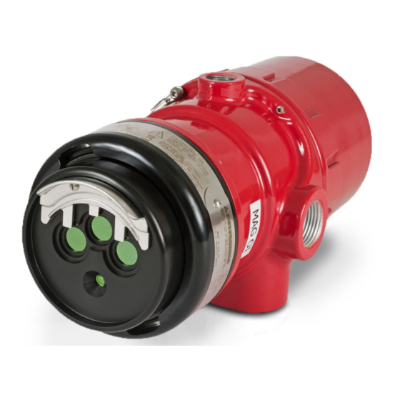
Det-Tronics X3301 Instructions Manual
Multispectrum ir flame detector with pulse output
Hide thumbs
Also See for X3301:
- Instructions manual (43 pages) ,
- Addendum (21 pages) ,
- Instructions manual (20 pages)

Subscribe to Our Youtube Channel
Related Manuals for Det-Tronics X3301


Summary of Contents for Det-Tronics X3301
- Page 1 Instructions Multispectrum IR Flame Detector with Pulse Output Model X3301 11.1 Rev: 12/13 95-8528...
-
Page 2: Table Of Contents
X3301 Model Matrix . . . . . . . . . . . . . . . . . . . -
Page 3: Description
When used as a field replacement, all operating features fault conditions. of the current controller are retained in addition to gaining the advanced features of the X3301 Flame Detector. In Microprocessor controlled heated optics increase typical applications, the four wire X3301 can utilize all resistance to moisture and ice. -
Page 4: Outputs
OUTPUTS The X3301 signals a fault condition when less than half of the detection range remains. This is indicated by the Relays Fault output and is evident by the yellow color of the The detector is furnished with fire and fault relays. The LED on the face of the detector. -
Page 5: Communication
Consult the factory with any questions on how to choose COMMUNICATION the optimum sensitivity level for the intended application. The X3301 is furnished with an RS-485 interface for communicating status and other information with external devices. The RS-485 supports MODBUS protocol, with the detector configured as a slave device. -
Page 6: General Application Information
(paint, oil, etc.) that will burn and possibly cause the sensitive devices. X3301 to alarm. Artificial Lighting The X3301 should not be located within 3 feet (0.9 m) of artificial lights. Excess heating of the detector could occur due to heat radiating from the lights. EMI/RFI Interference The X3301 is resistant to interference by EMI and RFI, and is EMC Directive compliant. -
Page 7: Installation
• Although IR detectors are less affected by smoke silicone be used. than other detectors, the X3301 should not be placed where rising combustion products can obscure its vision. If smoke is expected before fire, smoke DETECTOR POSITIONING... -
Page 8: Protection Against Moisture Damage
Wires should be stripped Refer to the Q9033 Mounting Arm and Collar Attachment 3/8 inch (9 mm). In some cases where the X3301 is Manual (95-8686) for additional mounting information. replacing existing pulse output detectors, the wiring See Figure 3 for dimensions. - Page 9 IMPORTANT the case and/or other conductors. At the controller/ If installing an X3301 in place of an existing fire panel end, connect the shield and power minus detector, be sure to move the “A” Lead (detector (–) to chassis (earth) ground either directly or...
- Page 10 NOTE: DO NOT CONNECT THE X3301 "A" LEAD (#2/12) TO TERMINAL J1-3 (290 VDC). R7404 CONTROLLER ZONE OUTPUT 1 10 TO 38 VDC – – ZONE OUTPUT 2 X3301 (A) +290 VDC ZONE OUTPUT 3 B - INPUT 1 ZONE OUTPUT 4...
- Page 11 NOTE: DETECTOR/CONTROLLER CIRCUITS MEET CLASS B, STYLE 2/12 DC+ ("A" LEAD) 0.5 REQUIREMENTS (SIGNALING LINES A AND C). SIGNAL ("B" LEAD) ("D" LEAD) GROUND FAULT PROTECTED SYSTEMS Figure 7—A Typical System, X3301 Detectors Wired to R7404 Star Logic Controller 11.1 95-8528...
- Page 12 DC– ("C" LEAD) NOTE: DETECTOR/CONTROLLER CIRCUITS MEET CLASS B, STYLE 2/12 DC+ ("A" LEAD) 0.5 REQUIREMENTS (SIGNALING LINES A AND C). SIGNAL ("B" LEAD) ("D" LEAD) GROUND FAULT PROTECTED SYSTEMS Figure 8—A Typical System, X3301 Detectors Wired to R7494 Controller 11.1 95-8528...
- Page 13 DC– ("C" LEAD) NOTE: DETECTOR/CONTROLLER CIRCUITS MEET CLASS B, STYLE 2/12 DC+ ("A" LEAD) 0.5 REQUIREMENTS (SIGNALING LINES A AND C). SIGNAL ("B" LEAD) ("D" LEAD) GROUND FAULT PROTECTED SYSTEMS Figure 9—A Typical System, X3301 Detectors Wired to R7495 Controller 11.1 95-8528...
- Page 14 NOTE: DO NOT CONNECT THE X3301 "A" LEAD (#2/12) TO TERMINAL J2-34 (290 VDC). R7405 CONTROLLER (NOT FM APPROVED) +24 VDC GROUND – X3301 DETECTOR 1 X3301 J2-44 J2-36 DETECTOR 2 X3301 +290 VDC J2-45 J2-37 DETECTOR 3 X3301 J2-46...
- Page 15 X3301 DETECTOR FIRE ALARM PANEL SPARE PULSE OUT SPARE COM FIRE 2 N.O. FIRE 2 N.C. FIRE 2 END OF LINE DEVICE 4 ALARM COM FAULT 1 RS-485 A N.O. FAULT 1 RS-485 B 24 VDC + MAN O i 24 VDC 24 VDC –...
-
Page 16: Startup Procedure
STARTUP PROCEDURE EOL Resistors To ensure that the insulating material of the wiring When installation of the equipment is complete, perform terminal block will not be affected by the heat generated one or more of the following tests: by EOL resistors, observe the following guidelines when installing the resistors. -
Page 17: Fire Alarm Test (Pulse Output To Fire Alarm Panel)
TROUBLESHOOTING 4. Press and hold the TEST button. The DETECTOR/ ZONE display indicates the counts per second (cps) received from the detector. If the counts per second WARNING exceeds 99, the FIRE LOGIC LEDs are illuminated to The sensor module (“front” half of the detector) indicate that the number shown on the display must contains no user serviceable components be multiplied by 10. -
Page 18: Maintenance
IMPORTANT X3301 Reflector Plates When used in extreme environments, the reflective X3301 models are supplied with either a black or a surface of the detector plate may eventually stainless steel reflector plate. These plates are not deteriorate, resulting in reoccurring faults and interchangeable. -
Page 19: Periodic Checkout Procedure
Meets FM, CSA, ATEX Directive and CE certification the highest sensitivity lying along the central axis. Unlike requirements conventional detectors, the X3301 provides full coverage • Class A wiring per NFPA-72 (Pulse output version is at a minimum of 70% of the maximum detection distance. - Page 20 Conduit connection: Four entries, 3/4 inch NPT or M25. Appendix B - CSA Conduit seal not required. Appendix C - ATEX/CE Appendix D - IECEx Appendix E - EN54 Appendix F - Additional approvals (11.9) 10.0 (25.4) (12.2) B2067 Figure 15—X3301 Dimensions in Inches (cm) 11.1 95-8528...
-
Page 21: Replacement Parts
Replacement kit for X3301 (5 Black Reflector Plates) 009208-001 with Inspector Connector and Monitor Part Number Description o i Replacement kit for X3301 (5 Stainless Steel Reflector Plates) 010831-001 000511-029 Converter RS485 to RS232 with Inspector Connector and Monitor... -
Page 22: X3301 Model Matrix
X3301 MODEL MATRIX MODEL DESCRIPTION X3301 Multispectrum IR Flame Detector TYPE MATERIAL Aluminum Stainless Steel (316) TYPE THREAD TYPE 4 PORT, Metric M25 4 PORT, 3/4" NPT TYPE OUTPUTS Relay and Pulse TYPE APPROVALS INMETRO (Brazil) VNIIPO/VNIIFTRI (Russia) FM/CSA/ATEX/CE/IECEx TYPE... -
Page 23: Performance Report
Zone 21 - AEx tb T130°C Db Tamb –40°C to +75°C Degree of protection provided by Enclosure IP66/67, Hazardous Locations for use in the U.S. The following accessories are FM approved for use with the X3301 Flame Detector: Part Number Description 102740-002... - Page 24 FM Approval and Performance Report – Continued RESPONSE CHARACTERISTICS Very High Sensitivity Fuel Size Distance feet (m) Average Response Time (seconds) n-Heptane 1 x 1 foot 210 (64)* n-Heptane** 1 x 1 foot 210 (64)* n-Heptane 1 x 1 foot 100 (30.5) n-Heptane 6 in.
- Page 25 FM Approval and Performance Report – Continued RESPONSE CHARACTERISTICS IN THE PRESENCE OF FALSE ALARM SOURCES Very High Sensitivity Distance Distance Average Response Time False Alarm Source Fire Source feet (m) feet (m) (seconds) Sunlight, direct, modulated, reflected — 6-inch propane 6 (1.8) <...
- Page 26 FM Approval and Performance Report – Continued T-Low Sensitivity Distance Distance Average Response Time False Alarm Source Fire Source feet (m) feet (m) (seconds) Sunlight, direct, unmodulated, reflected* — 1 x 1 foot n-Heptane 35 (10.7) < 6 Sunlight, direct, modulated, reflected* —...
- Page 27 FM Approval and Performance Report – Continued FALSE ALARM IMMUNITY Very High Sensitivity Distance False Alarm Source Modulated Response Unmodulated Response feet (m) Sunlight, direct, reflected — No alarm No alarm Vibration No alarm Radio frequency interference 1 (0.3) No alarm (keyed) No alarm (steady) Arc welding 40 (12.2)
- Page 28 FM Approval and Performance Report – Continued FIELD OF VIEW Very High Sensitivity Distance Horizontal Avg. Horiz. Response Vertical Avg. Vert. Response Fuel Size feet (m) (degrees) Time (seconds) (degrees) Time (seconds 150* n-Heptane 1 x 1 foot (45.7) n-Heptane 1 x 1 foot (30.5) n-Heptane...
- Page 29 FM Approval and Performance Report – Continued Medium Sensitivity Distance Horizontal Avg. Horiz. Response Vertical Avg. Vert. Response Fuel Size feet (m) (degrees) Time (seconds) (degrees) Time (seconds n-Heptane 1 x 1 foot (22.9) n-Heptane 1 x 1 foot (15.2) Diesel** 1 x 1 foot (18.3)
- Page 30 FM Approval and Performance Report – Continued HIGH RESOLUTION FIELD OF VIEW 0° 0° 15° 15° 70 (21.3) 15° 15° 210 (64) 30° 30° 30° 30° 60 (18.3) 180 (54.9) 45° 45° 45° 45° 50 (15.2) 150 (45.7) 40 (12.2) 120 (36.5) 30 (9.1) 90 (27.4)
- Page 31 FM Approval and Performance Report – Continued 0° 0° 15° 15° 15° 15° 210 (64) 150 (45.7) 30° 30° 30° 30° 135 (41.2 180 (54.9) 120 (36.5) 45° 45° 45° 45° 150 (45.7) 105 (32) 90 (27.4) 120 (36.5) 75 (22.9) 90 (27.4) 60 (18.3) 45 (13.7)
- Page 32 FM Approval and Performance Report – Continued 0° 0° 15° 15° 100 (30.5) 15° 15° 70 (21.3) 30° 30° 90 (27.4) 30° 30° 60 (18.3) 80 (24.4) 45° 45° 45° 45° 70 (21.3) 50 (15.2) 60 (18.3) 40 (12.2) 50 (15.2) 30 (9.1) 40 (12.2) 30 (9.1)
-
Page 33: Appendix B - Csa Approval
Relay contacts rated 30 Vdc, 5 Amps. NOTE Hazardous location testing has been successfully completed on the Model X3301 series from an ambient temperature range of –55°C to +125°C; however, the detector label marking indicates –40°C to +75°C. The following accessories are CSA approved for use with the X3301 Flame Detector:... -
Page 34: Appendix C - Atex / Ce Approval
EOL resistors must be ceramic, wirewound type, rated 5 watts minimum, with actual power dissipation not to exceed 2.5 watts. The Multispectrum infrared (IR) flame detector type X3301 is to be installed in places where there is a low risk of mechanical damage. - Page 35 IP66/IP67 for the apparatus. Unused conduit entries shall be closed with suitable blanking elements. NOTE For ATEX installations, the X3301 Flame Detector housing must be electrically connected to earth ground. The following accessories are ATEX approved for use with the X3301 Flame Detector: Part Number...
-
Page 36: Appendix Diecex Approval
EOL resistors must be ceramic, wirewound type, rated 5 watts minimum, with actual power dissipation not to exceed 2.5 watts. flame detector type X3301 is to be installed in places where there is a low risk of The Multispectrum infrared (IR) mechanical damage. -
Page 37: Appendix Een54 Approvals
The IR-flame detector configured to High or Very High sensitivity corresponds to class 1. The IR-flame detector configured to T-Low or Low sensitivity corresponds to class 2. The following accessories are EN54-10 and EN54-17 approved for use with the X3301 Flame Detector: Part Number... -
Page 38: Appendix Fadditional Approvals
APPENDIX F ADDITIONAL APPROVALS RUSSIA NOTE The following Russian approval applies to existing installations that include Det-Tronics’ R7XXX controllers and require a factory replacement of older pulse detectors. VNIIPO CERTIFICATE OF CONFORMITY TO TECHNICAL REGULATIONS, GOST R 53325-2009 BRAZIL UL-BR 12.0093X Ex d e IIC T6-T5 Gb IP66/IP67 Ex tb IIIC T130°C... - Page 39 95-8528 FlexSonic ® Acoustic PointWatch Eclipse ® IR FlexVu ® Universal Display X3301 Multispectrum Eagle Quantum Premier ® Leak Detector IR Flame Detector Combustible Gas Detector with GT3000 Toxic Gas Detector Safety System Specifications subject to change without notice .
Need help?
Do you have a question about the X3301 and is the answer not in the manual?
Questions and answers