Det-Tronics X3301 Instructions Manual
Multispectrum ir flame detector
Hide thumbs
Also See for X3301:
- Instructions manual (39 pages) ,
- Addendum (21 pages) ,
- Instructions manual (20 pages)
Table of Contents
Advertisement
Advertisement
Table of Contents

Related Manuals for Det-Tronics X3301


Summary of Contents for Det-Tronics X3301
- Page 1 Instructions Multispectrum IR Flame Detector X3301 Rev: 1/16 95-8704...
-
Page 2: Table Of Contents
..... . 19 X3301 Model Matrix ....20 IMPORTaNT SaFETy NOTES . -
Page 3: Description
The X3301 includes the Automatic o i ® (Optical Integrity) feature — a calibrated performance test that is automatically performed once per minute to verify A tri-color LED on the detector faceplate indicates complete detector operation capabilities. -
Page 4: Led
The status of the LED Automatic o i always follows the status of the relays. The X3301 includes the Automatic o i feature — a An alarm condition will normally over-ride a fault calibrated performance test that is automatically... -
Page 5: Communication
• Distance between the hazard and the flame detector COMMuNICATION Additional information on X3301 Flame Detector The X3301 is furnished with an RS-485 interface for communicating status and other information performance results and sensitivities can be with external devices. The RS-485 supports... -
Page 6: General Application Information
T-Low sensitivity, or at Low sensitivity. ImPORTaNT SafETy NOTES Artificial Lighting WarnIng The X3301 should not be located within 3 feet Do not open the detector assembly in a (0.9 m) of artificial lights. Excess heating of the hazardous area when power is applied. -
Page 7: Installation
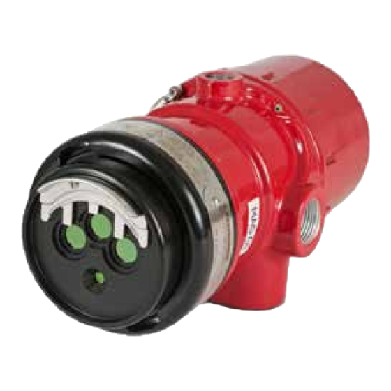
OF DETECTOR FIELD OF VIEW VIEWING WINDOW (3) CORRECT D1974 o i MAGNET NOTE: DETECTOR MUST ALWAYS BE AIMED DOWNWARD AT LEAST 10 TO 20 DEGREES. F2068 DETECTOR STATUS INDICATOR Figure 1—Detector Orientation Relative to Horizon Figure 2—Front View of the X3301 95-8704... -
Page 8: Detector Orientation
Wires should between the o i plate and the viewing windows. be stripped 3/8 inch (9 mm). A minimum input voltage of 18 Vdc must be present at the X3301. Important If removed, the o i plate must be securely... - Page 9 – Figures 7 and 8 provide examples of WarnIng typical installations with a X3301 wired to a fire alarm panel. All entries must contain appropriately rated plugs or fittings. It is required that each – If the detector is equipped with a 0–20 mA plug or fitting be wrench-tightened to an output, refer to Figures 9 through 12.
- Page 10 COM FAULT RS485 A NO FAULT NO FAULT RS485 B +Vin +Vin MAN O i –Vin –Vin –Vin E2061 Figure 5—X3301 Wiring Terminal Identification 3/8 INCH (10 MM) GAP MINIMUM B2126 BULKHEAD Figure 6—EOL Resistor Installation (For Ex d Wiring only) 95-8704...
- Page 11 X3301 DETECTOR FIRE ALARM PANEL mA + mA – SPARE SHIELD mA + REF mA – REF SPARE COM FIRE 2 COM AUX COM FIRE NO FIRE 2 NO AUX NO FIRE RESISTOR 4 NC FIRE 2 NC AUX NC FIRE...
- Page 12 –Vin –Vin –Vin O i TEST 1 O i TEST 1 Figure 9—X3301 Detector Wired for Non-Isolated 0 to 20 ma Current Output (Sourcing) Figure 11—X3301 Detector Wired for Isolated 0 to 20 ma Current Output (Sourcing) 24 VDC X3301 IR DETECTOR –...
- Page 13 Figure 13—X3301 Terminal Block (EQP Model) SHIELD SHIELD COM 1 A COM 2 A COM 1 B COM 2 B PWR SHIELD PWR SHIELD +Vin +Vin –Vin –Vin C2089 Figure 14—Wiring Terminal Identification for X3301 EQP Model 95-8704...
- Page 14 CH 1 CH 2 CH 3 CH 4 CH 5 CH 6 CH 7 CH 8 RELAY 1 RELAY 2 RELAY 3 RELAY 4 DIGITAL INPUTS RELAY 5 RELAY 6 RELAY 7 RELAY 8 95-8704...
-
Page 15: Setting Device Network Addresses (Eqp Model Only)
OF ALL CLOSED ROCKER SWITCHES CLOSED = ON to gain access to the network address A2190 Figure 17—address Switches for X3301 switches. For hazardous areas, the area must be de-classified before attempting disassembly of the device. Always observe precautions for handling electrostatic sensitive devices. -
Page 16: Startup Procedure
Disable any extinguishing equipment that is The use of the Enhanced Flame Inspector connected to the system. cable and software from Det-Tronics can be considered to determine the nature of the Apply input power to the system. fault condition. Refer to instruction manual Initiate an o i test (see “Magnetic o i /... -
Page 17: Maintenance
NOTE may eventually deteriorate, resulting in Refer to the X3301 Safety manual, number reoccurring o i faults and the need for o i 9 5 - 8 7 2 0 , fo r s p e c i fi c re q u i re m e n t s and recommendations applicable to plate replacement. -
Page 18: Periodic Checkout Procedure
X3301 Reflector plates • Long detection range to carbonaceous fires X3301 models are supplied with either a black or • Unequaled false alarm rejection a stainless steel reflector plate. These plates are • Responds to a fire in the presence of not interchangeable. -
Page 19: Specifications
The detector has a 90° cone of vision (horizontal) with the highest sensitivity lying along the central POWER UP TIME— axis. Unlike conventional detectors, the X3301 Fault indication clears after 0.5 second; device provides full coverage at a minimum of 70% of is ready to indicate an alarm condition after 30 the maximum detection distance. - Page 20 ENCLOSURE MaTERIaL— CERTIFICaTION— Copper-free aluminum (painted) or Stainless Steel (316/CF8M Cast). ® VIBRaTION— Conformance per FM 3260: 2000, MIL-STD 810C (Curve AW), DNV Note 2.4 (Class B). WIRING— Field wiring screw terminals are UL/CSA rated for up to 14 AWG wire, and are DIN/VDE rated for 2.5 mm wire.
-
Page 21: Replacement Parts
– Q9033B for aluminum and stainless steel REpLACEMENT pARTs LIsT detectors part Number Description o i Replacement kit for X3301 (5 Black Reflector Plates) ACCEssORIEs 009208-001 with Inspector Connector and Monitor o i Replacement kit for X3301 (5 Stainless Steel Reflector... -
Page 22: X3301 Model Matrix
X3301 MODEL MATRIX MODEL DEsCRIpTION Multispectrum IR Flame Detector X3301 TypE MATERIAL Aluminum Stainless Steel (316) TypE ThREAD TypE 4 Port, Metric M25 4 Port, 3/4" NPT TypE OuTpuTs Relay Relay and 0-20 mA Eagle Quantum Premier (EQP) Relay and Pulse... -
Page 23: High Resolution Field Of View Diagrams
HIGH RESOlUTION fIElD Of VIEW DIaGRamS 0° 0° 15° 15° 15° 15° 70 (21.3) 265 (80.7) 30° 30° 30° 30° 240 (73.1) 60 (18.3) 45° 45° 200 (60.9) 45° 45° 50 (15.2) 160 (48.7) 40 (12.2) 120 (36.8) 30 (9.1) 80 (24.3) 20 (6.1) 40 (12.1) - Page 24 high Resolution Field of view Diagrams – Continued 0° 0° 15° 15° 40 (12.2) 15° 15° 125 (38.1) 30° 30° 30° 30° 120 (36.6) 35 (10.7) 105 (32) 45° 30 (9.1) 45° 45° 45° 90 (27.4) 25 (7.6) 75 (22.9) 20 (6.1) 60 (18.3) 15 (4.6)
- Page 25 high Resolution Field of view Diagrams – Continued 0° 0° 15° 15° 15° 15° 125 (38.1) 235 (71.6) 30° 30° 100 (30.5) 30° 30° 210 (64) 90 (27.4) 45° 45° 180 (54.9) 80 (24.4) 45° 45° 70 (21.3) 150 (45.7) 60 (18.3) 120 (36.5) 50 (15.2)
- Page 26 high Resolution Field of view Diagrams – Continued 0° 0° 15° 15° 15° 15° 70 (21.3) 100 (30.5) 30° 30° 30° 30° 90 (27.4) 60 (18.3) 80 (24.4) 45° 45° 45° 45° 50 (15.2) 70 (21.3) 60 (18.3) 40 (12.2) 50 (15.2) 30 (9.1) 40 (12.2)
-
Page 27: Appendix A - Fm Approval And Performance Report
Tamb –40°C to +75°C IP66 Class I, Zone 1, AEx db IIC T6...T5 T6 (Tamb –40°C to +60°C) T5 (Tamb –40°C to +75°C) IP66/IP67 The following accessories are FM approved for use with the X3301 Flame Detector: part Number Description 102740-002 Magnet 007739-001... - Page 28 FM Approval and performance Report – Continued REspONsE ChARACTERIsTICs very high sensitivity Fuel size Distance feet (m) Average Response Time (seconds)*** 1 x 1 foot 265 (80.7)* 1 x 1 foot 250 (76.2) n-Heptane 1 x 1 foot 100 (30.5) 6 in.
- Page 29 FM Approval and performance Report – Continued T-Low sensitivity Fuel size Distance feet (m) Average Response Time (seconds)*** n-Heptane 1 x 1 foot 50 (15.24) <4 Methanol 1 x 1 foot 30 (9.14) Methane 32 inch plume 30 (9.14) Propane 32 inch plume 30 (9.14) *** Add 2 seconds for EQP model...
- Page 30 FM Approval and performance Report – Continued REspONsE ChARACTERIsTICs IN ThE pREsENCE OF FALsE ALARM sOuRCEs very high sensitivity Distance Distance Average Response Time False Alarm source Fire source feet (m) feet (m) (seconds)*** Sunlight, direct, modulated, reflected — 6-inch propane 6 (1.8) Sunlight, direct, unmodulated, reflected —...
- Page 31 FM Approval and performance Report – Continued T-Low sensitivity Distance Distance Average Response Time False Alarm source Fire source feet (m) feet (m) (seconds)*** Sunlight, direct, modulated, reflected* — 1 x 1 foot n-Heptane 15 (4.6) Sunlight, direct, unmodulated, reflected* —...
- Page 32 FM Approval and performance Report – Continued FALsE ALARM IMMuNITy very high sensitivity Distance False Alarm source Modulated Response unmodulated Response feet (m) Sunlight, direct, reflected — No alarm No alarm Vibration No alarm Radio frequency interference 1 (0.3) No alarm (keyed) No alarm (steady) Arc welding 40 (12.2)
- Page 33 FM Approval and performance Report – Continued Low sensitivity Distance Modulated False Alarm source unmodulated Response feet (m) Response Sunlight, direct, reflected — No alarm No alarm Vibration No alarm No alarm Radio frequency interference — No alarm Arc welding 5 (1.5) No alarm No alarm...
- Page 34 FM Approval and performance Report – Continued Medium sensitivity Distance horizontal Avg. Resp vertical Avg. Resp vertical Avg. Resp Fuel size feet (m) L, R (°) Time (s)*** Down (°) Time (s)*** up (°) Time (s)*** 1 x 1 foot 75 (22.9) +/–...
-
Page 35: Appendix B Csa Approval
– Explosive atmospheres. Part 7: Equipment protection by increased safety "e" CAN/CSA-C22.2 No. 60079-31:2015 – Explosive atmospheres. Part 31: Equipment dust ignition protection by enclosure "t" The following accessories are CSA approved for use with the X3301 Flame Detector: part Number... -
Page 36: Appendix Catex Approval
• EOL resistors must be ceramic, wirewound type, rated 5 watts minimum, with actual power dissipation not to exceed 2.5 watts. • The Multispectrum infrared (IR) flame detector type X3301 is to be installed in places where there is a low risk of mechanical damage. •... - Page 37 IP66 for the apparatus. Unused conduit entries shall be closed with suitable blanking elements. NOTE For ATEX installations, the X3301 Flame Detector housing must be electrically connected to earth ground. The following accessories are ATEX approved for use with the X3301 Flame Detector:...
-
Page 38: Appendix Diecex Approval
EOL resistors must be ceramic, wirewound type, rated 5 watts minimum, with actual power dissipation not to exceed 2.5 watts. • The Multispectrum infrared (IR) flame detector type X3301 is to be installed in places where there is a low risk of mechanical damage. •... -
Page 39: Appendix Een54 Approvals
<90°. The IR-flame detector configured to all sensitivity levels corresponds to class 1. The following accessories are EN54-10, EN54-13, and EN54-17 approved for use with the X3301 Flame Detector: part Number... -
Page 40: Appendix F - Offshore Approvals
IR Flame Detector Type X3301 for use in Ships, High Speed & Light Craft, and Offshore Applications. Application Location Classes: Location classes for X3301 IR Flame Detector with Mounting arm Q9033B / Q9033a and optional Q9033 Collar attachment (Shaded areas show Det- Tronics approved location classes) -
Page 41: Appendix Gadditional Approvals
ULC/ORD-C386:2015 - Flame Detector Applies to specific models – refer to the SIL 2 Certified Flame detectors meeting these requirements must be X3301 Safety manual (95-8720) for details. employed in accordance with appropriate parts of the following: – CAN/ULC-S524, the Standard for Installation of Fire RussIA &... -
Page 42: Appendix H - Declaration Of Conformity
aPPENDIX H DECLARATION OF CONFORMITy 95-8704... - Page 43 Phone: 952.946.6491 Corporate Office © 2016. Detector Electronics Corporation. all rights reserved. Toll-free: 800.765.3473 6901 West 110 Street Det-Tronics manufacturing system is certified to ISO 9001— Fax: 952.829.8750 Minneapolis, MN 55438 USa the world’s most recognized quality management standard. det-tronics@det-tronics.com www.det-tronics.com...
Need help?
Do you have a question about the X3301 and is the answer not in the manual?
Questions and answers