Table of Contents
Advertisement
Quick Links
Advertisement
Table of Contents

Related Manuals for Det-Tronics X Series


Summary of Contents for Det-Tronics X Series
- Page 1 Addendum Det-Tronics X-Series Flame Detectors with Pulse Output 95-8790...
-
Page 2: Table Of Contents
Table of Contents DESCRIPTION......1 Outputs ......2 (Optical Integrity) . -
Page 3: Description
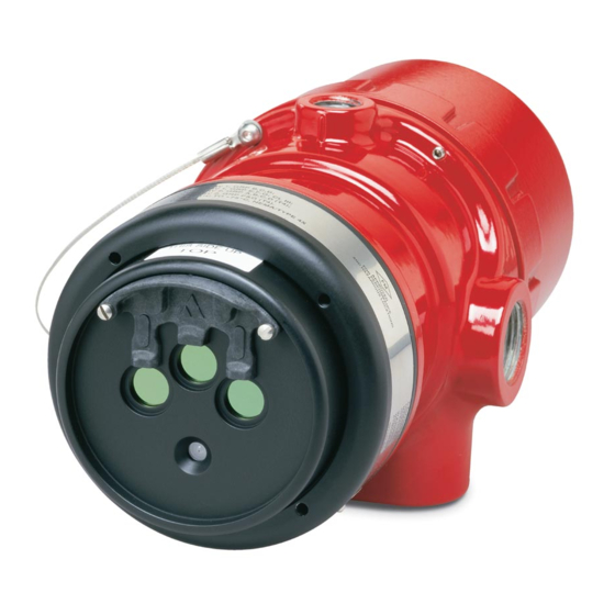
ADDENDUM Det-Tronics X-Series Flame Detectors with Pulse Output WARNING Be sure to read and understand the entire instruction manual before installing or operating the flame detection system. Any deviation from the recommendations in this manual may impair system performance and compromise safety. -
Page 4: Outputs
successful, the controller indicates a fire and OUTPUTS the appropriate zone output is active. Relays NOTE The detectors are furnished with fire and fault If a detector is in a fault condition, a relays. The relays are rated 5 amperes at 30 Vdc. successful Mag or Man test cannot... -
Page 5: General Application Information
O b s e r v e p re ca u t i o n s fo r h a n d l i n g Performance Report, in each models manual for electrostatic sensitive devices. third-party approved fire test results. Additional fire test results are available from Det-Tronics. ATTENTION For models X2200, X2200M, X5200, and IMPORTANT APPLICATION CONSIDERATIONS... -
Page 6: Detector Wiring
“B” and “D” leads of all other detectors in order SPARE PULSE OUT to prevent false alarms resulting from crosstalk between zones. It is recommended that the SPARE “A” and “C” leads also be shielded to provide COM FIRE COM FIRE maximum immunity to EMI/RFI. - Page 7 NOTE: DO NOT CONNECT THE DETECTOR "A" LEAD (#2/12) TO TERMINAL J1-3 (290 VDC). R7404 CONTROLLER ZONE OUTPUT 1 10 TO 38 VDC – – ZONE OUTPUT 2 X3301 (A) +290 VDC ZONE OUTPUT 3 B - INPUT 1 ZONE OUTPUT 4 DETECTOR 1 B - INPUT 2 ZONE OUTPUT 5...
- Page 8 NOTE: DO NOT CONNECT THE DETECTOR "A" LEAD (#2/12) TO TERMINAL J1-3 (290 VDC). R7404 STAR LOGIC CONTROLLER +24 VDC ZONE OUTPUT 1 CIRCUIT GROUND ZONE OUTPUT 2 – X3301 +290 VDC ZONE OUTPUT 3 B1 - INPUT SIGNAL ZONE OUTPUT 4 DETECTOR 1 B2 - INPUT SIGNAL ZONE OUTPUT 5...
- Page 9 R7494 CONTROLLER +24 VDC ZONE OUTPUT 1 CIRCUIT GROUND ZONE OUTPUT 2 – X3301 +24 VDC ZONE OUTPUT 3 B1 - INPUT SIGNAL ZONE OUTPUT 4 DETECTOR 1 B2 - INPUT SIGNAL ZONE OUTPUT 5 B3 - INPUT SIGNAL ZONE OUTPUT 6 B4 - INPUT SIGNAL ZONE OUTPUT 7 X3302...
- Page 10 R7495 CONTROLLER (NOT FM APPROVED) +24 VDC – GROUND X3301 DETECTOR 1 X3302 J2-44 J2-36 DETECTOR 2 X2200 J2-45 J2-37 DETECTOR 3 X2200G J2-46 J2-38 DETECTOR 4 X5200 J2-47 J2-39 DETECTOR 5 X5200G J2-48 J2-40 DETECTOR 6 X9800 J2-49 J2-41 DETECTOR 7 X3301 J2-50...
- Page 11 NOTE: DO NOT CONNECT THE DETECTOR "A" LEAD (#2/12) TO TERMINAL J2-34 (290 VDC). R7405 CONTROLLER (NOT FM APPROVED) +24 VDC GROUND – X3301 DETECTOR 1 X3302 J2-44 J2-36 DETECTOR 2 X2200 +290 VDC J2-45 J2-37 DETECTOR 3 X2200G J2-46 J2-38 DETECTOR 4 X5200...
-
Page 12: Startup Procedure
STARTUP PROCEDURE Place the keylock switch in the TEST position. When installation of the equipment is complete, Simultaneously press and release the perform one or more of the following tests: SELECT and TEST buttons. The Status display will change from a “1” to an “8” •... -
Page 13: Maintenance
MAINTENANCE PERIODIC CHECKOUT PROCEDURE A checkout of the system using the Mag IMPORTANT feature should be performed on a Periodic flamepath inspections are not regularly scheduled basis to ensure that the recommended, since the product is not system is operating properly. To test the system, intended to be serviced and provides proper perform the “Manual Test,”... -
Page 14: Model Matrix
X-SERIES FLAME DETECTOR MODEL MATRIX MODEL DESCRIPTION Multispectrum IR Flame Detector X3301 X3302 Multispectrum IR Flame Detector X2200 UV Flame Detector X2200M UV Flame Detector with Molybdenum Tube X2200G UV Flame Detector with Kr85 Free Source Tube UV/IR Flame Detector X5200 X5200M UV/IR Flame Detector with Molybdenum Tube... - Page 16 Specifications subject to change without notice. All trademarks are the property of their respective owners. © 2020 Carrier. All rights reserved. Corporate Office Phone: +1 952.941.5665 6901 West 110 Street Toll-free: +1 800.765.3473 Minneapolis, MN 55438 USA Fax: 952.829.8750 www.det-tronics.com det-tronics@carrier.com...
Need help?
Do you have a question about the X Series and is the answer not in the manual?
Questions and answers