Det-Tronics X3301 Instructions Manual
Protect-ir multispectrum ir flame detector with pulse output
Hide thumbs
Also See for X3301:
- Instructions manual (43 pages) ,
- Addendum (21 pages) ,
- Instructions manual (39 pages)
Table of Contents

Related Manuals for Det-Tronics X3301


Summary of Contents for Det-Tronics X3301
- Page 1 Instructions 95-8528 Protect•IR ® Multispectrum IR Flame Detector with Pulse Output X3301 Detector Electronics Corporation 6901 West 110th Street • Minneapolis, Minnesota 55438 USA 4/03 95-8528 Tel: 952.941.5665 or 800.765.3473 • Fax: 952.829.8750...
-
Page 2: Table Of Contents
X3301 Terminal Block ........6 Detector Positioning ..........4 Figure 5 X3301 Wiring Terminal Identification ...6 Detector Orientation ..........4 Figure 6 A Typical System, X3301 Detectors Wired Wire Size and Type ..........5 to R7404 Controller ........7 Protection Against Moisture Damage .......5 Wiring Procedure............5 Figure 7 A Typical System, X3301 Detectors Wired EOL Resistors ............6... -
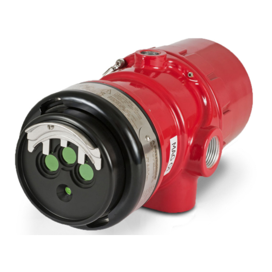
Page 3: Description
The X3301 housing is available in copper- to gaining the advanced features of the X3301 detector. free aluminum or stainless steel, with NEMA 4X and In typical applications, the four wire X3301 can utilize all IP66 rating. existing system wiring. -
Page 4: Detector Status Indicator
Automatic Oi NOTE Refer to the Appendix for FM verification of Det- The X3301 includes the Automatic Optical Integrity (o i ) Tronics’ patented Optical Integrity o i ™ function. feature — a calibrated performance test that is automatically performed once per minute to verify complete detector operation capabilities. -
Page 5: General Application Information
Artificial Lighting Data logging capability is also provided. Status The X3301 should not be located within 3 feet of conditions such as normal, power down, general and o i artificial lights. Excess heating of the detector could faults, pre-alarm, fire alarm, time and temperature are occur due to heat radiating from the lights. -
Page 6: Installation
CENTER AXIS OF DETECTOR FIELD OF VIEW Refer to Figure 2 and ensure that the o i plate will be oriented as shown when the X3301 is mounted and sighted. This will ensure proper operation of the o i B1974 CORRECT... -
Page 7: Wire Size And Type
X3301. IMPORTANT The use of shielded cable is required to protect against If installing an X3301 in place of an existing interference caused by EMI and RFI. When using detector, be sure to move the “A” Lead (detector... -
Page 8: Figure
SPARE PULSE OUT SPARE COM FIRE N.O. FIRE N.C. FIRE COM FAULT RS-485 A N.O. FAULT RS-485 B 24 VDC + MAN Oi 24 VDC – 24 VDC – Figure 4—X3301 Terminal Block A2070 Figure 5—X3301 Wiring Terminal Identification 95-8528... -
Page 9: Figure 6-A Typical System, X3301 Detectors Wired To R7404 Controller
NOTE: DO NOT CONNECT THE X3301 "A" LEAD (#2/12) TO TERMINAL J1-3 (290 VDC). R7404 CONTROLLER ZONE OUTPUT 1 10 TO 38 VDC – – ZONE OUTPUT 2 X3301 (A) +290 VDC ZONE OUTPUT 3 B - INPUT 1 ZONE OUTPUT 4... -
Page 10: Figure 7-A Typical System, X3301 Detectors Wired To R7404 Star Logic Controller
NOTE: DETECTOR/CONTROLLER CIRCUITS MEET CLASS B, STYLE 2/12 DC+ ("A" LEAD) 0.5 REQUIREMENTS (SIGNALING LINES A AND C). SIGNAL ("B" LEAD) GROUND FAULT PROTECTED SYSTEMS Oi ("D" LEAD) Figure 7—A Typical System, X3301 Detectors Wired to R7404 Star Logic Controller 95-8528... -
Page 11: Figure 8-A Typical System, X3301 Detectors Wired To R7494 Controller
DC– ("C" LEAD) NOTE: DETECTOR/CONTROLLER CIRCUITS MEET CLASS B, STYLE 2/12 DC+ ("A" LEAD) 0.5 REQUIREMENTS (SIGNALING LINES A AND C). SIGNAL ("B" LEAD) Oi ("D" LEAD) GROUND FAULT PROTECTED SYSTEMS Figure 8—A Typical System, X3301 Detectors Wired to R7494 Controller 95-8528... -
Page 12: A Typical System, X3301 Detectors Wired To R7495 Controller
DC– ("C" LEAD) NOTE: DETECTOR/CONTROLLER CIRCUITS MEET CLASS B, STYLE 2/12 DC+ ("A" LEAD) 0.5 REQUIREMENTS (SIGNALING LINES A AND C). SIGNAL ("B" LEAD) Oi ("D" LEAD) GROUND FAULT PROTECTED SYSTEMS Figure 9—A Typical System, X3301 Detectors Wired to R7495 Controller 95-8528... -
Page 13: Figure 10 A Typical System, X3301 Detectors Wired To R7405 Controller
NOTE: DO NOT CONNECT THE X3301 "A" LEAD (#2/12) TO TERMINAL J2-34 (290 VDC). R7405 CONTROLLER +24 VDC GROUND – X3301 DETECTOR 1 X3301 J2-44 J2-36 DETECTOR 2 X3301 +290 VDC J2-45 J2-37 DETECTOR 3 X3301 J2-46 J2-38 DETECTOR 4... -
Page 14: Figure 11A Eex D Wiring Option
X3301 DETECTOR FIRE ALARM PANEL SPARE PULSE OUT SPARE COM FIRE 2 N.O. FIRE 2 N.C. FIRE 2 END OF LINE DEVICE 4 ALARM COM FAULT 1 RS-485 A N.O. FAULT 1 RS-485 B 24 VDC + MAN Oi 24 VDC 24 VDC –... -
Page 15: Startup Procedure
5. Verify that all detectors in the system are properly aimed at the area to be protected. (The Det-Tronics COUNT TEST MODE (Output to Controller) Q1201C Laser Aimer is recommended for this The detector can be tested using the Count Test mode. -
Page 16: Troubleshooting
Important: Disconnect To maintain maximum sensitivity, the viewing windows wiring at the detector before checking system of the X3301 must be kept relatively clean. Refer to the wiring for continuity. procedure below for cleaning instructions. 6. If all wiring checks out and cleaning of the o i... -
Page 17: Oi Plate Removal
oi PLATE REMOVAL LOOSEN TWO CAPTIVE SCREWS 1. Loosen the two captive screws, then grasp the o i plate by the visor and remove it from the detector. See Figure 13. 2. Thoroughly clean the o i plate reflective surfaces, holding it by its edges to avoid leaving fingerprints on the inside reflective surface. -
Page 18: Figure 14 X3301 Dimensions In Inches (Cm)
Class I, Div. 1, Groups B, C and D; Unlike conventional detectors, the X3301 provides full Class II, Div. 1, Groups E, F, and G; coverage at a minimum of 70% of the maximum Class I, Div. -
Page 19: Replacement Parts
ORDERING INFORMATION 0539 II 2 GD When ordering, please specify: EEx d IIC T4–T6 DEMKO 01 ATEX 130204 X3301 IR Flame Detector with Pulse Output T6 (T = –55°C to +60°C). T5 (T = –55°C to +75°C). Specify Sensitivity: T4 (T = –55°C to +125°C). -
Page 20: Appendix A
APPENDIX A Factory Mutual (FM) Approvals Description and Performance Report THE FOLLOWING ITEMS, FUNCTIONS AND OPTIONS DESCRIBE THE FM APPROVAL: • Explosion-proof for Class I, Div. 1, Groups B, C and D Hazardous (Classified) Locations per FM 3615. • Dust-ignition proof for Class II/III, Div. 1, Groups E, F and G Hazardous (Classified) Locations per FM 3615. •... - Page 21 Factory Mutual (FM) Approval Description and Performance Report – Continued RESPONSE CHARACTERISTICS: Very High Sensitivity Fuel Size Distance Average Response Time (feet) (seconds) n-Heptane 1 x 1 foot 210* n-Heptane** 1 x 1 foot 210* n-Heptane 1 x 1 foot n-Heptane 6 in.
- Page 22 Factory Mutual (FM) Approval Description and Performance Report – Continued OPTICAL INTEGRITY TEST: The detector generated an optical fault in the presence of contamination on any single or combination of lens surfaces resulting in a loss of approximately 50% of its detection range, verifying that the detector performs a calibrated Automatic optical integrity (oi) test for each sensor.
- Page 23 Factory Mutual (FM) Approval Description and Performance Report – Continued FALSE ALARM IMMUNITY: Very High Sensitivity False Alarm Source Distance Modulated Response Unmodulated Response (feet) Sunlight, direct, reflected — No alarm No alarm Vibration No alarm Radio frequency interference No alarm (keyed) No alarm (steady) Arc welding No alarm...
- Page 24 Factory Mutual (FM) Approval Description and Performance Report – Continued FIELD OF VIEW: Very High Sensitivity Fuel Size Distance Horizontal Avg. Horiz. Response Time Vertical Avg. Vert. Response Time (feet) (degrees) (seconds) (degrees) (seconds) n-Heptane 1 x 1 foot 150* –45 –30 n-Heptane...
- Page 25 Factory Mutual (FM) Approval Description and Performance Report – Continued Medium Sensitivity Fuel Size Distance Horizontal Avg. Horiz. Response Time Vertical Avg. Vert. Response Time (feet) (degrees) (seconds) (degrees) (seconds) n-Heptane 1 x 1 foot –45 –30 n-Heptane 1 x 1 foot –45 –30 Diesel**...
- Page 26 Factory Mutual (FM) Approval Description and Performance Report – Continued 0° 0° 15° 15° 70 ft 15° 15° 80 ft 30° 30° 30° 30° 60 ft 70 ft 60 ft 45° 45° 45° 45° 50 ft 50 ft 40 ft 40 ft 30 ft 20 ft...
- Page 27 Factory Mutual (FM) Approval Description and Performance Report – Continued 0° 0° 15° 15° 15° 15° 210 ft 100 ft 30° 30° 30° 30° 90 ft 180 ft 80 ft 45° 45° 45° 45° 150 ft 70 ft 60 ft 120 ft 50 ft 90 ft...
Need help?
Do you have a question about the X3301 and is the answer not in the manual?
Questions and answers