Det-Tronics X5200 Instructions Manual
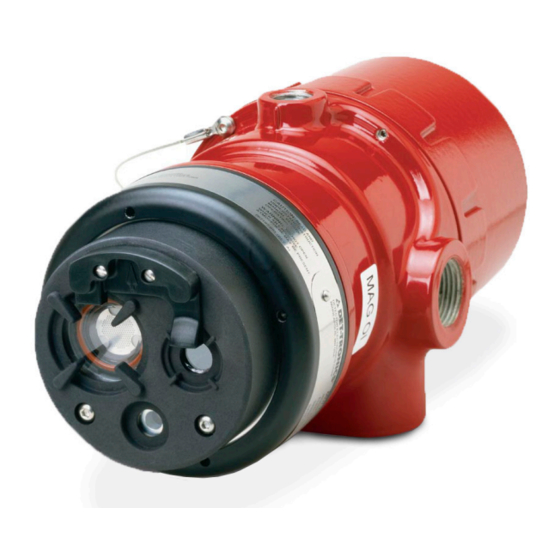
Uvir flame detector with pulse output
Hide thumbs
Also See for X5200:
- Instructions manual (35 pages) ,
- Addendum (21 pages) ,
- Instructions manual (20 pages)

Related Manuals for Det-Tronics X5200


Summary of Contents for Det-Tronics X5200
- Page 1 Instructions UVIR Flame Detector with Pulse Output X5200, X5200G, X5200M Rev: 11/15 95-8547...
-
Page 2: Table Of Contents
IMPORTANT SAFETY NOTES....6 X5200 Model Matrix ..... . 22 INSTALLATION. -
Page 3: Description
ATTENTION The X5200 includes the Automatic o i ® (Optical Integrity) feature — a calibrated performance test that is automatically performed once per minute to verify complete detector operation capabilities. -
Page 4: Outputs
OUTPUTS ATTENTION The X5200 contains a source tube that is filled Relays with a gas mixture containing Krypton 85 (Kr The detector is furnished with fire and fault relays. The a radioactive material. Radioactive materials are relays are rated 5 amperes at 30 Vdc. -
Page 5: Communication
UV and IR sensor. These options determine the type of logic that the detector will During the entire test, the detector gives no indication use for processing fire signals to customize the X5200 to of alarm. the application. -
Page 6: Uv Detector Options
X5200. Welding rods with clay binders applications. Most false alarm sources have short do not burn and will not be detected by the X5200. transient UV signatures, while fire creates a long UV However, system bypass is always recommended, since signature over many seconds. -
Page 7: False Alarm Sources
If the window cannot be x-rays, and gamma radiation. eliminated or the detector location changed, contact Det-Tronics for recommendations regarding window materials that will not attenuate radiation. NOTE Radiation generated by false alarm sources such... -
Page 8: Important Safety Notes
IMPORTANT SAFETY NOTES Table 2— UV and IR Absorbing Gases and Vapors The following is a partial list of compounds that exhibit WARNING significant UV absorption characteristics. These are also usually hazardous vapors. While generally of little Do not open the detector assembly in a hazardous consequence in small amounts, these gases can restrict area when power is applied. -
Page 9: Installation
The Refer to Figure 2 and ensure that the o i plate will following factors should also be taken into consideration: be oriented as shown when the X5200 is mounted and sighted. This will ensure proper operation of the •... -
Page 10: Protection Against Moisture Damage
Devices certified for hazardous locations shall be cable is recommended. Wires should be stripped installed in accordance with EN/IEC 60079-14 and 3/8 inch (9 mm). In some cases where the X5200 is NEC 505. replacing existing pulse output detectors, the wiring CAUTION and power supplies may not be adequate. - Page 11 See Figure 3 for dimensions. Detector Wiring IMPORTANT If installing an X5200 in place of an existing detector, be sure to move the “A” Lead (detector power) at the controller from the +290 Vdc source to the +24 Vdc source. Do not apply 290 Vdc to the X5200.
- Page 12 NOTE: DO NOT CONNECT THE X5200 "A" LEAD (#2/12) TO TERMINAL J1-3 (290 VDC). R7404 CONTROLLER ZONE OUTPUT 1 10 TO 38 VDC – ZONE OUTPUT 2 – X5200 (A) +290 VDC ZONE OUTPUT 3 B - INPUT 1 ZONE OUTPUT 4...
- Page 13 2/12 DC+ ("A" LEAD) SIGNAL ("B" LEAD) NOTE: DETECTOR/CONTROLLER CIRCUITS MEET CLASS B, STYLE 0.5 REQUIREMENTS (SIGNALING LINES A AND C). ("D" LEAD) GROUND FAULT PROTECTED SYSTEMS Figure 7—A Typical System, X5200 Detectors Wired to R7404 Star Logic Controller 95-8547...
- Page 14 DC– ("C" LEAD) 2/12 DC+ ("A" LEAD) SIGNAL ("B" LEAD) NOTE: DETECTOR/CONTROLLER CIRCUITS MEET CLASS B, STYLE 0.5 REQUIREMENTS (SIGNALING LINES A AND C). ("D" LEAD) GROUND FAULT PROTECTED SYSTEMS Figure 8—A Typical System, X5200 Detectors Wired to R7494 Controller 95-8547...
- Page 15 DC– ("C" LEAD) 2/12 DC+ ("A" LEAD) NOTE: DETECTOR/CONTROLLER CIRCUITS MEET CLASS B, STYLE SIGNAL ("B" LEAD) 0.5 REQUIREMENTS (SIGNALING LINES A AND C). ("D" LEAD) GROUND FAULT PROTECTED SYSTEMS Figure 9—A Typical System, X5200 Detectors Wired to R7495 Controller 95-8547...
- Page 16 NOTE: DO NOT CONNECT THE X5200 "A" LEAD (#2/12) TO TERMINAL J2-34 (290 VDC). R7405 CONTROLLER (NOT FM APPROVED) +24 VDC GROUND – X5200 DETECTOR 1 X5200 J2-44 J2-36 DETECTOR 2 X5200 +290 VDC J2-45 J2-37 DETECTOR 3 X5200 J2-46...
- Page 17 X5200 DETECTOR FIRE ALARM PANEL SPARE PULSE OUT SPARE COM FIRE 2 N.O. FIRE 2 N.C. FIRE 2 END OF LINE DEVICE 4 ALARM COM FAULT 1 RS-485 A N.O. FAULT 1 RS-485 B + Vin MAN O i 24 VDC –...
-
Page 18: Eol Resistors
STARTUP PROCEDURE EOL RESISTORS To ensure that the insulating material of the wiring When installation of the equipment is complete, apply terminal block will not be affected by the heat generated power and allow 20 to 30 minutes for the detector’s by EOL resistors, observe the following guidelines when heated optics to reach equilibrium. -
Page 19: Fire Alarm Test (Pulse Output To Fire Alarm Panel)
TROUBLESHOOTING 3. Press the SELECT button until the desired zone is displayed on the ZONE indicator on the controller front panel. WARNING 4. Press and hold the TEST button. The DETECTOR/ The sensor module (“front” half of the detector) ZONE display indicates the counts per second (cps) contains no user serviceable components and received from the detector. -
Page 20: Maintenance
PLATE REMOVAL AND REPLACEMENT To maintain maximum sensitivity and false alarm 1. Disable any extinguishing equipment that is resistance, the viewing windows of the X5200 must be connected to the unit. kept relatively clean. Refer to the following procedure for 2. -
Page 21: Features
SPECIFICATIONS NOTE If the backup battery is depleted, there is no effect OPERATING VOLTAGE— on the operation of the flame detector, but the time 24 Vdc nominal (18 Vdc minimum, 30 Vdc maximum). stamping of the data log may be affected. Maximum ripple is 2 volts peak-to-peak. - Page 22 CONE OF VISION— DIMENSIONS— The detector has a 90° cone of vision (horizontal) with See Figure 16 the highest sensitivity lying along the central axis. See Figure 15. WIRING— Field wiring screw terminals are UL/CSA rated for up to 14 AWG wire, and are DIN/VDE rated for 2.5 mm wire.
-
Page 23: Replacement Parts
Pulse Output Detector Electronics office so that a Return Material Authorization (RMA) number can be assigned. A Refer to the X5200 Model Matrix below for details written statement describing the malfunction must Q9033 Mounting Arm is required: accompany the returned device or component to –... -
Page 24: X5200 Model Matrix
X5200 MODEL MATRIX MODEL DESCRIPTION UV/IR Flame Detector X5200 X5200G UV/IR Flame Detector with KR Free Source Tube X5200M UV/IR Flame Detector with Molybdenum Tube TYPE MATERIAL Aluminum Stainless Steel (316) TYPE THREAD TYPE 4 PORT, METRIC M25 4 PORT, 3/4" NPT... -
Page 25: Appendix A - Fm Approval And Performance Report
T6 (Tamb –40°C to +60°C) T5 (Tamb –40°C to +75°C) ZONE 21, AEx tb IIIC T80°C Tamb –40°C to +75°C IP66/IP67 The following accessories are FM approved for use with the X5200 Flame Detector: Part Number Description 102740-002 Magnet 007739-001... - Page 26 FM Approval and Performance Report – Continued RESPONSE CHARACTERISTICS High Sensitivity UV & IR, Hi Arc, TDSA On, Quick Fire Off Fuel Size Distance feet (m) Typical Response Time (seconds) n-Heptane 1 x 1 foot 50 (15.2) Methane 32 inch plume 35 (10.7) High Sensitivity UV &...
- Page 27 FM Approval and Performance Report – Continued RESPONSE CHARACTERISTICS IN THE PRESENCE OF FALSE ALARM SOURCES High Sensitivity, Hi Arc, TDSA On, Quick Fire Off Distance Distance Average Response Time False Alarm Source Fire Source feet (m) feet (m) (seconds) Sunlight, direct, modulated/unmodulated —...
- Page 28 FM Approval and Performance Report – Continued FIELD OF VIEW High Sensitivity UV & IR, Hi Arc, TDSA On, Quick Fire Off Distance Horizontal Typical Horz. Response Vertical Typical Vert. Response Fuel Size feet (m) (degrees) Time (seconds) (degrees) Time (seconds) n-Heptane 1 x 1 foot (7.6)
- Page 29 FM Approval and Performance Report – Continued MODEL X5200M The X5200M uses a sensor that has a broader spectrum than the standard sensor. It is designed to detect fires with unusual chemistry such as black powder. Consult factory for usage recommendations. X5200M RESPONSE CHARACTERISTICS High Sensitivity UV &...
-
Page 30: Appendix B - Csa Approval
APPENDIX B CSA APPROVAL DIVISION CLASSIFICATION: Ultraviolet Infrared Flame Detector/Controller X5200 series, rated 18-30 Vdc, 2.8 Watts to 17.5 Watts. Relay contacts rated 5 Amps @ 30 Vdc. CLASS 4818 04 - SIGNAL APPLIANCES - Systems - For Hazardous Locations Class I, Division 1, Groups B, C, and D (T5);... -
Page 31: Appendix Catex Approval
EOL resistors must be ceramic, wirewound type, rated 5 watts minimum, with actual power dissipation not to exceed 2.5 watts. • The Ultraviolet Infrared (UVIR) flame detector type X5200 is to be installed in places where there is a low risk of mechanical damage. •... - Page 32 IP66/IP67 for the apparatus. Unused conduit entries shall be closed with suitable blanking elements. NOTE For ATEX installations, the X5200 detector housing must be electrically connected to earth ground. The following accessories are ATEX approved for use with the X5200 Flame Detector: Part Number...
-
Page 33: Appendix Diecex Approval
EOL resistors must be ceramic, wirewound type, rated 5 watts minimum, with actual power dissipation not to exceed 2.5 watts. • The Ultraviolet Infrared (UVIR) flame detector type X5200 is to be installed in places where there is a low risk of mechanical damage. •... - Page 34 Specifications subject to change without notice. All trademarks are the property of their respective owners. © 2020 Detector Electronics Corporation. All rights reserved. Corporate Office Phone: +1 952.941.6665 6901 West 110 th Street Toll-free: +1 800.765.3473 Minneapolis, MN 55438 USA Fax: 952.829.8750 www.det-tronics.com det-tronics@carrier.com...
Need help?
Do you have a question about the X5200 and is the answer not in the manual?
Questions and answers