Det-Tronics X5200 Series Instructions Manual
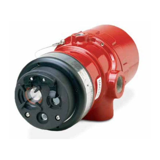
Uvir flame detector
Hide thumbs
Also See for X5200 Series:
- Instructions manual (34 pages) ,
- Addendum (21 pages) ,
- Addendum (16 pages)
Table of Contents
Advertisement
Quick Links
Advertisement
Table of Contents

Related Manuals for Det-Tronics X5200 Series


Summary of Contents for Det-Tronics X5200 Series
- Page 1 Instructions 95-8546 UVIR Flame Detector X5200 12.1 Rev: 6/13 95-8546...
-
Page 2: Table Of Contents
Table of Contents DESCRIPTION . . . . . . . . . . . . . . . . . . . . . . . . . . . . . . 1 TROUbLEShOOTINg . -
Page 3: Description
0 to 20 mA output (in addition to the three relays) 30 Vdc. – Pulse output for compatibility with existing Detector Electronics Corporation (Det-Tronics ® ) controller The Fire Alarm relay has redundant terminals and based systems (with fire and fault relays) -
Page 4: Led
The EQP model is designed for use exclusively with the same test that a maintenance person with a test Det-Tronics' Eagle Quantum Premier system. lamp would perform — once every minute, 60 times per detector communicates with the system controller over hour. -
Page 5: Communication
These features can be performed at any time and becomes active, and again when the status changes. eliminate the need for testing with a non-calibrated Data is accessible using Det-Tronics' Inspector Connector external test lamp. accessory, RS-485, or the EQP Controller. -
Page 6: Uv Detector Options
See Appendix A for third-party approved fire test results. applications). Additionally, when the Quick Fire feature Additional fire test results are available from Det-Tronics. and TDSA signal processing are used in conjuction, the detector maintains an ability to respond to fires that start very small and grow in size and intensity over time. -
Page 7: False Alarm Sources
If the window cannot be high voltage corona, x-rays, and gamma radiation. eliminated or the detector location changed, contact Det-Tronics for recommendations regarding window materials that will not attenuate radiation. NOTE Radiation generated by false alarm sources such... -
Page 8: Important Safety Notes
ImPORTaNT SafETy NOTES Table 3—UV and IR absorbing gases and Vapors The following is a partial list of compounds that exhibit WarnIng significant UV absorption characteristics . These are Do not open the detector assembly in a hazardous also usually hazardous vapors . While generally of little area when power is applied. -
Page 9: Installation
(40 oz./inches [28.2 N . cm] recommended). within both the Field of View (FOV) and detection range of the detector. Det-Tronics' Q1201C Laser Aimer is recommended for establishing the detector's FOV. Refer to Appendix A for specific information regarding detector range and FOV. -
Page 10: Protection Against Moisture Damage
pROTECTION AgAINsT MOIsTuRE DAMAgE NOTE R e f e r t o “ Po w e r C o n s u m p t i o n” i n t h e It is important to take proper precautions during “Specifications”... -
Page 11: Eol Resistors (Not Used With Eqp Model)
Relay and 0-20 mA Output Models EOL REsIsTORs (Not used with EQp Model) Follow the instructions below to install the X5200. To ensure that the insulating material of the wiring terminal block will not be affected by the heat generated 1. - Page 12 X5200 DETECTOR FIRE ALARM PANEL 4-20 mA + 4-20 mA – SPARE 4-20 mA + REF 4-20 mA – REF SPARE COM FIRE 2 COM AUX COM FIRE N.O. FIRE 2 N.O. AUX N.O. FIRE E.O.L. DEVICE 4 N.C. FIRE 2 N.C.
- Page 13 X5200 DETECTOR X5200 DETECTOR 4-20 mA + 4-20 mA – 4-20 mA + 4-20 mA – AT 24 VDC AT 24 VDC 4-20 mA – REF 4-20 mA + REF – – 4 TO 20 mA 4 TO 20 mA 24 VDC 24 VDC –...
- Page 14 EQp Model 5. Check all field wiring to be sure that the proper connections have been made. 1. Connect external wires to the appropriate terminals inside the device junction box, shown in Figure 13. 6. Replace the device cover and apply input power. See Figure 14 for terminal identification.
- Page 15 CH 1 CH 2 CH 3 CH 4 CH 5 CH 6 CH 7 CH 8 RELAY 1 RELAY 2 RELAY 3 RELAY 4 DIGITAL INPUTS RELAY 5 RELAY 6 RELAY 7 RELAY 8 12.1 95-8546...
-
Page 16: Setting Device Network Addresses
ADDRESS SWITCHES SENSOR MODULE REMOVED FROM HOUSING A2191 figure 16—Location of address Switches The address number is binary encoded with each switch sETTINg DEVICE NETWORk ADDREssEs having a specific binary value with switch 1 being the (EQ and EQp Models Only) LSB (Least Significant Bit), see Figure 17. -
Page 17: Startup Procedure
IR source. 5. Verify that all detectors in the system are properly UV and IR sensors If no fire exists, remove aimed at the area to be protected. (Det-Tronics' in pre-alarm, or one UV and IR sources 16 mA... -
Page 18: Maintenance
REMOVAL AND REpLACEMENT actuation. 1. Disable any extinguishing equipment that is To clean the windows and o i plate, use Det-Tronics' connected to the unit. window cleaner (p/n 001680-001) and a soft cloth, cotton 2. Loosen the two captive screws, then grasp the o i swab or tissue and refer to the following procedure: plate by the visor and remove it from the detector. -
Page 19: Periodic Checkout Procedure
fEaTuRES pERIODIC CHECkOuT pROCEDuRE In compliance with SIL 2, a checkout of the system using • Responds to a fire in the presence of modulated the Mag o i or Man o i feature should performed regularly blackbody radiation (i.e. heaters, ovens, turbines) to ensure that the system is operating properly. -
Page 20: Specifications
SPECIfICaTIONS 100% REPRESENTS THE MAXIMUM DETECTION DISTANCE FOR A GIVEN FIRE. THE SENSITIVITY INCREASES AS THE ANGLE OF INCIDENCE DECREASES. OPERaTINg VOLTagE— VIEWING ANGLE 24 Vdc nominal (18 Vdc minimum, 30 Vdc maximum). 0° 15° 15° Maximum ripple is 2 volts peak-to-peak. 100 ft (30.5 m) 30°... - Page 21 CONE Of VISION— ThREaD SIZE— The detector has a 90° cone of vision (horizontal) with Conduit connection: Four entries, 3/4 inch NPT or M25. the highest sensitivity lying along the central axis. Conduit seal not required. See Figure 19. ShIPPINg WEIghT (approximate)— Aluminum: 7 pounds (3.2 kilograms).
-
Page 22: Replacement Parts
NOTE 101197-003 Stop Plug, M25, SS, IP66 010816-001 Stop Plug, 20 Pack, 3/4”NPT, AL Det-Tronics reserves the right to apply a service 010817-001 Stop Plug, 20 Pack, 3/4”NPT, SS charge for repairing returned product damaged as 010818-001 Stop Plug, 20 Pack, M25, AL, IP66 a result of improper packaging. -
Page 23: X5200 Model Matrix
X5200 MODEL MATRIX MODEL DEsCRIpTION UV/IR Flame Detector X5200 X5200M UV/IR Flame Detector with Molybdenum Tube TypE MATERIAL Aluminum Stainless Steel (316) TypE THREAD TypE 4 Port, Metric M25 4 Port, 3/4" NPT TypE OuTpuTs Relay Relay and 4-20 mA Eagle Quantum Premier (EQP) Relay and Pulse Addressable Module Only (Third Party Type)*... -
Page 24: Performance Report
aPPENDIX a FM AppROVAL AND pERFORMANCE REpORT THE FOLLOWING ITEMS, FUNCTIONS AND OPTIONS DESCRIBE THE FM APPROVAL: • Explosion-proof for Class I, Div. 1, Groups B, C and D (T5) Hazardous (Classified) Locations per FM 3615. • Dust-ignition proof for Class II/III, Div. 1, Groups E, F and G (T5) Hazardous (Classified) Locations per FM 3615. •... - Page 25 FM Approval and performance Report – Continued REspONsE CHARACTERIsTICs High sensitivity uV & IR, Hi Arc, TDsA On, Quick Fire Off Fuel size Distance feet (m) Typical Response Time (seconds)* n-Heptane 1 x 1 foot 50 (15.2) Methane 32 inch plume 35 (10.7) *Add 2 seconds for EQP model.
- Page 26 FM Approval and performance Report – Continued REspONsE CHARACTERIsTICs IN THE pREsENCE OF FALsE ALARM sOuRCEs High sensitivity, Hi Arc, TDsA On, Quick Fire Off Distance Distance Average Response Time False Alarm source Fire source feet (m) feet (m) (seconds)* Sunlight, direct, modulated/unmodulated —...
- Page 27 FM Approval and performance Report – Continued FIELD OF VIEW High sensitivity uV & IR, Hi Arc, TDsA On, Quick Fire Off Distance Horizontal Typical Horz. Response Vertical Typical Vert. Response Fuel size feet (m) (degrees) Time (seconds)* (degrees) Time (seconds)* n-Heptane 1 x 1 foot (7.6)
- Page 28 FM Approval and performance Report – Continued MODEL X5200M The X5200M uses a sensor that has a broader spectrum than the standard sensor. It is designed to detect fires with unusual chemistry such as black powder. Consult factory for usage recommendations. X5200M REspONsE CHARACTERIsTICs High sensitivity uV &...
-
Page 29: Appendix B - Csa Approval
Class I, Division 2, Groups A, B, C, and D (T3); Class II, Division 2, Groups F and G (T3); Class III; Enclosure NEMA/Type 4X; Ultraviolet Infrared Flame Detector/Controller X5200 series, rated 18-30 Vdc, 2.8 Watts to 17.5 Watts. Relay contacts rated 5 Amps @ 30 Vdc. -
Page 30: Appendix C - Atex / Ce Approval
aPPENDIX C ATEX / CE AppROVAL EC-TypE EXAMINATION CERTIFICATE DEMkO 02 ATEX 132195X Increased Safety Model Flameproof Model II 2 G II 2 G 0539 0539 ® II 2 D ® II 2 D APPROVED APPROVED Ex d e IIC T6–T5 Gb Ex d IIC T6–T5 Gb Ex tb IIIC T80°C Ex tb IIIC T80°C... - Page 31 NOTE Operational performance verified from –40°C to +75°C. NOTE An optional third party addressable module can only be used within the Ex d flameproof model unless the addressable module is component certified as Ex e for use within the Ex d e increased safety model. NOTE Refer to “EOL Resistors”...
-
Page 32: Appendix Diecex Approval
aPPENDIX D IECEx AppROVAL IECEx CERTIFICATE OF CONFORMITy DEMkO IECEx ULD 06.0018X Ex d e IIC T6-T5 Gb Ex d IIC T6-T5 Gb Ex tb IIIC T80°C Ex tb IIIC T80°C T6 (T amb = –50°C to +60°C) T6 (T amb = –55°C to +60°C) T5 (T amb = –50°C to +75°C) T5 (T amb =–55°C to +75°C) IP66/IP67. -
Page 33: Appendix Een54 Approvals
aPPENDIX E EN54 AppROVALs Conventional Output LON Output AgENCy Certificate/approval Certificate/approval basis of approval basis of approval Number Number VdS – 0786 – CPD – 20778 EN 54-10 + A1 — — Construction Product Directive VdS 2344 G 203085 VdS 2504 —... -
Page 34: Appendix F Additional Approvals
aPPENDIX f ADDITIONAL AppROVALs sIL 2 IEC 61508 Certified SIL 2 Capable. Applies to specific models – refer to the SIL 2 Certified X5200 Safety Manual (95-8672) for details. RussIA VNIIfTRI CERTIfICaTE Of CONfORmITy gOST R 51330 .X-99 2ExdeIICT6/T5 IP66 T6 (Tamb = –55°C to +60°C) T5 (Tamb = –55°C to +75°C). - Page 35 GT3000 Toxic Gas Detector Safety System Det-Tronics and o i (Optical Integrity) are registered trademarks or trademarks of Detector Electronics Corporation in the United States, other countries, or both. Other company, product, or service names may be trademarks or service marks of others.
Need help?
Do you have a question about the X5200 Series and is the answer not in the manual?
Questions and answers