
Subscribe to Our Youtube Channel
Related Manuals for Det-Tronics UVIR Series


Summary of Contents for Det-Tronics UVIR Series
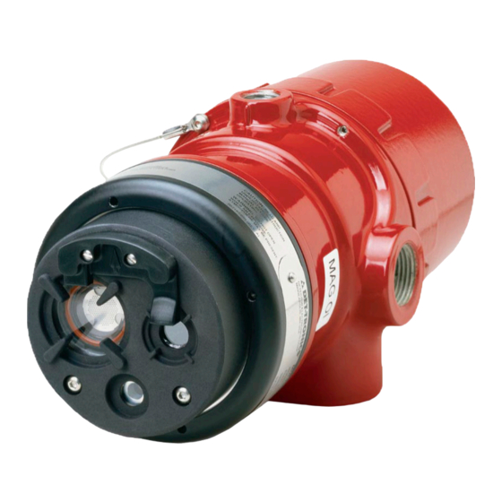
- Page 1 Instructions UVIR Flame Detector Series X5200, X5200G, and X5200M 17.3 Rev: 4/17 95-8546...
-
Page 2: Table Of Contents
Table of Contents DESCRIPTION ......1 TROUBLESHOOTING ..... . . 15 Outputs . -
Page 3: Description
0 to 20 mA output (in addition to the three relays) 30 Vdc. – Pulse output for compatibility with existing Detector Electronics Corporation (Det-Tronics) controller The Fire Alarm relay has redundant terminals and based systems (with fire and fault relays) normally open / normally closed contacts, normally de-energized operation, and latching or non-latching –... -
Page 4: Led
— a calibrated performance test that is The EQP model is designed for use exclusively with automatically performed once per minute to verify the Det-Tronics Eagle Quantum Premier system. The complete detector operation capabilities. No testing detector communicates with the system controller over with an external test lamp is required. -
Page 5: Communication
The detector signals a fault condition when less than half of NOTE the detection range remains. This is indicated by the Fault The EQP model uses LON/SLC communication. RS-485 output and is evident by the yellow color of the LED on the and HART communication are not available on the EQP face of the detector. -
Page 6: Uv Detector Options
See Appendix A for third-party approved fire test results. applications). Additionally, when the Quick Fire feature Additional fire test results are available from Det-Tronics. and TDSA signal processing are used in conjunction, the detector maintains an ability to respond to fires that start very small and grow in size and intensity over time. -
Page 7: False Alarm Sources
If the window cannot be high voltage corona, x-rays, and gamma radiation. eliminated or the detector location changed, contact Det-Tronics for recommendations regarding window materials that will not attenuate radiation. NOTE Radiation generated by false alarm sources such... -
Page 8: Important Safety Notes
IMPORTANT SAFETY NOTES Table 3—UV and IR Absorbing Gases and Vapors The following is a partial list of compounds that exhibit WARNING significant UV absorption characteristics. These are Do not open the detector assembly in a hazardous also usually hazardous vapors. While generally of little area when power is applied. -
Page 9: Installation
INSTALLATION • Dense fog, rain as well as certain gases and vapors (see Table 3) can absorb UV and IR radiation and reduce the sensitivity of the detector. NOTE The recommended lubricant for threads and O-rings • If possible, fire tests can be conducted to verify is a silicone-free grease (p/n 005003-001) available correct detector positioning and coverage. -
Page 10: Protection Against Moisture Damage
PROTECTION AGAINST MOISTURE DAMAGE NOTE R e f e r t o “ Po w e r C o n s u m p t i o n” i n t h e It is important to take proper precautions during “Specifications”... - Page 11 Detector Installation IMPORTANT Install the mounting arm assembly on a rigid surface. Do not test any wiring connected to the detector The ideal installation surface should be free of vibration with a meg-ohmmeter. Disconnect wiring at and suitable to receive 3/8 inch or M10 bolts with a length the detector before checking system wiring for of at least 1 inch (25 mm).
- Page 12 DETECTOR FIRE ALARM PANEL mA + mA – SPARE SHIELD mA + REF mA – REF SPARE COM FIRE 2 COM AUX COM FIRE NO FIRE 2 NO AUX NO FIRE DEVICE 4 NC FIRE 2 NC AUX NC FIRE ALARM COM FAULT 1 RS485 A...
- Page 13 DETECTOR DETECTOR mA + mA + mA – mA – AT 24 VDC AT 24 VDC mA – REF mA + REF – – 24 VDC 24 VDC – – MAN O i MAN O i +Vin +Vin D2139 D2138 –Vin –Vin –Vin...
- Page 14 EQP Model 5. Check all field wiring to be sure that the proper connections have been made. 1. Connect external wires to the appropriate terminals inside the device junction box, shown in Figure 13. 6. Replace the device cover and apply input power. See Figure 14 for terminal identification.
- Page 15 CH 1 CH 2 CH 3 CH 4 CH 5 CH 6 CH 7 CH 8 RELAY 1 RELAY 2 RELAY 3 RELAY 4 DIGITAL INPUTS RELAY 5 RELAY 6 RELAY 7 RELAY 8 17.3 95-8546...
-
Page 16: Setting Device Network Addresses
ADDRESS SWITCHES SENSOR MODULE REMOVED FROM HOUSING A2191 Figure 16—Location of Address Switches The address number is binary encoded with each switch SETTING DEVICE NETWORK ADDRESSES having a specific binary value with switch 1 being the (EQ and EQP Models Only) LSB (Least Significant Bit), see Figure 17. -
Page 17: Startup Procedure
STARTUP PROCEDURE Table 4—Current Level Output Troubleshooting Guide Current Level Status Action When installation of the equipment is complete, perform (±0.3 mA) the “Fire Alarm Test” below. 0 mA Power Fault Check system wiring. 1 mA General Fault Cycle power. FIRE ALARM TEST 2 mA Clean windows. -
Page 18: Maintenance
MAINTENANCE LOOSEN TWO CAPTIVE SCREWS IMPORTANT Pe r i o d i c fl a m e p a t h i n s p e c t i o n s a re n o t recommended, since the product is not intended to be serviced and provides proper ingress protection to eliminate potential deterioration of the flamepaths. -
Page 19: Periodic Checkout Procedure
FEATURES PERIODIC CHECKOUT PROCEDURE In compliance with SIL 2, a checkout of the system • Responds to a fire in the presence of modulated using the Mag or Man feature should performed blackbody radiation (i.e., heaters, ovens, turbines) regularly to ensure that the system is operating properly. without false alarm Refer to Table 1 in the X5200 and X5200M Safety manual •... -
Page 20: Specifications
SPECIFICATIONS 100% REPRESENTS THE MAXIMUM DETECTION DISTANCE FOR A GIVEN FIRE. THE SENSITIVITY INCREASES AS THE ANGLE OF INCIDENCE DECREASES. OPERATING VOLTAGE— VIEWING ANGLE 24 Vdc nominal (18 Vdc minimum, 30 Vdc maximum). 0° 15° 15° Maximum ripple is 2 volts peak-to-peak. 30°... - Page 21 CONE OF VISION— THREAD SIZE— The detector has a 90° cone of vision (horizontal) with Conduit connection: Four entries, 3/4 inch NPT or M25. the highest sensitivity lying along the central axis. Conduit seal not required. See Figure 19. SHIPPING WEIGHT (Approximate)— Aluminum: 7 pounds (3.2 kilograms).
-
Page 22: Replacement Parts
007739-001 Magnet and Extension Pole NOTE 007240-001 Q1116A1001, Air Shield (AL) Det-Tronics reserves the right to apply a service 007818-001 Q1118A1001 Aluminum Air Shield/Flange Mount (AL) charge for repairing returned product damaged as 007818-002 Q1118S1001 Stainless Steel Air Shield/Flange Mount (SS) -
Page 23: X5200 Series Model Matrix
X5200 SERIES MODEL MATRIX MODEL DESCRIPTION UV/IR Flame Detector X5200 X5200G UV/IR Flame Detector with Kr Free Source Tube X5200M UV/IR Flame Detector with Molybdenum Tube TYPE MATERIAL Aluminum Stainless Steel (316) TYPE THREAD TYPE 4 Port, Metric M25 4 Port, 3/4" NPT TYPE OUTPUTS Relay... -
Page 24: Appendix A - Fm Approval And Performance Report
APPENDIX A FM APPROVAL AND PERFORMANCE REPORT THE FOLLOWING ITEMS, FUNCTIONS, AND OPTIONS DESCRIBE THE FM APPROVAL FOR THE X5200 AND X5200M: • Explosion-proof for Class I, Div. 1, Groups B, C, and D (T5) Hazardous (Classified) Locations per FM 3615. •... - Page 25 FM Approval and Performance Report – Continued X5200 RESPONSE CHARACTERISTICS High Sensitivity UV & IR, Hi Arc, TDSA On, Quick Fire Off Fuel Size Distance feet (m) Typical Response Time (seconds)* n-Heptane 1 x 1 foot 50 (15.2) Methane 32 inch plume 35 (10.7) *Add 2 seconds for EQP model.
- Page 26 FM Approval and Performance Report – Continued X5200 RESPONSE CHARACTERISTICS IN THE PRESENCE OF FALSE ALARM SOURCES High Sensitivity, Hi Arc, TDSA On, Quick Fire Off Distance Distance Average Response Time False Alarm Source Fire Source feet (m) feet (m) (seconds)* Sunlight, direct, modulated/unmodulated —...
- Page 27 FM Approval and Performance Report – Continued X5200 FIELD OF VIEW High Sensitivity UV & IR, Hi Arc, TDSA On, Quick Fire Off Distance Horizontal Typical Horz. Response Vertical Typical Vert. Response Fuel Size feet (m) (degrees) Time (seconds)* (degrees) Time (seconds)* n-Heptane 1 x 1 foot...
- Page 28 FM Approval and Performance Report – Continued MODEL X5200M The X5200M uses a sensor that has a broader spectrum than the standard sensor. It is designed to detect fires with unusual chemistry such as black powder. Consult factory for usage recommendations. X5200M RESPONSE CHARACTERISTICS High Sensitivity UV &...
-
Page 29: Appendix B - Csa Approval
APPENDIX B CSA APPROVAL DIVISION CLASSIFICATION: Ultraviolet Infrared Flame Detector/Controller X5200 series, rated 18-30 Vdc, 2.8 Watts to 17.5 Watts. Relay contacts rated 5 Amps @ 30 Vdc. CLASS 4818 04 - SIGNAL APPLIANCES - Systems - For Hazardous Locations Class I, Division 1, Groups B, C, and D (T5);... -
Page 30: Appendix Catex Approval
APPENDIX C ATEX APPROVAL EC-TYPE EXAMINATION CERTIFICATE DEMKO 02 ATEX 132195X Increased Safety Model Flameproof Model II 2 G II 2 G 0539 0539 ® II 2 D ® II 2 D APPROVED APPROVED Ex db eb IIC T6...T5 Ex db IIC T6...T5 Ex tb IIIC T80°C Ex tb IIIC T80°C T6 (Tamb = –50°C to +60°C) - Page 31 NOTE Operational performance verified from –40°C to +75°C. NOTE Refer to “EOL Resistors” section for installation details. All cable entry devices and blanking elements shall be certified to “E-generation” or “ATEX” standards, in type of explosion protection increased safety “e” or flameproof enclosure “d”...
-
Page 32: Appendix Diecex Approval
APPENDIX D IECEx APPROVAL CERTIFICATE OF CONFORMITY IECEx ULD 06.0018X Ex db eb IIC T6...T5 Ex db IIC T6...T5 Ex tb IIIC T80°C Ex tb IIIC T80°C T6 (T amb = –50°C to +60°C) T6 (T amb = –55°C to +60°C) T5 (T amb = –50°C to +75°C) T5 (T amb =–55°C to +75°C) IP66/IP67. -
Page 33: Appendix Een54 Approvals
APPENDIX E EN54 APPROVALS APPLICABLE TO MODEL X5200 Conventional Output LON Output Certification Bodies Certificate/Approval Certificate/Approval Basis of Approval Basis of Approval Number Number VdS – — — — — Construction Product Regulation VdS 2344 G 203085 VdS 2504 — —... -
Page 34: Appendix Fadditional Approvals
APPENDIX F ADDITIONAL APPROVALS SIL 2 BRAZIL IEC 61508 UL-BR 17.0216X Certified SIL 2 Capable. Ex db eb IIC T6...T5 Applies to specific models – refer to the SIL 2 Certified Ex tb IIIC T80°C X5200 and X5200M Safety Manual (95-8672) for details. T6 (Tamb -50°C TO +60°C) T5 (Tamb -50°C TO +75°C) IP66/IP67... - Page 35 All trademarks are the property of their respective owners. 6901 West 110 th Street © 2017 Detector Electronics Corporation. All rights reserved. Toll-free: 800.765.3473 Fax: 952.829.8750 Minneapolis, MN 55438 USA Det-Tronics manufacturing system is certified to ISO 9001— the world’s most recognized quality management standard. www.det-tronics.com det-tronics@det-tronics.com...
Need help?
Do you have a question about the UVIR Series and is the answer not in the manual?
Questions and answers