Table of Contents
Advertisement
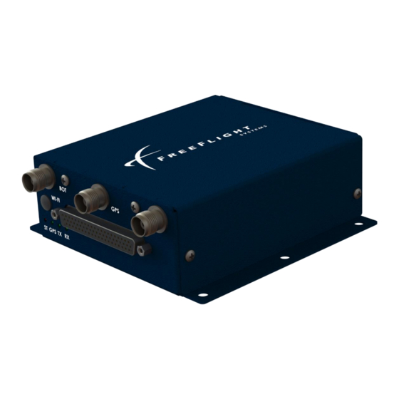
ADS-B FDL-DB Dual Band Series
Installation Information
Part Numbers
P/N 87334-XX-XXXX
Document No. 88552
Disclaimer: This manual revision is a controlled engineering release copy which is currently under review
and pending TSO approval. This document has been loaned only to specific customers and must not be
redistributed without the written consent of FreeFlight Systems Engineering
This document contains FreeFlight Systems proprietary information. It is loaned for limited purposes only and
remains the property of FreeFlight Systems. It may not be reproduced in whole or in part without written consent
of FreeFlight Systems and must not be disclosed to persons not having need of such disclosure consistent with
the purpose of the loan. The document is to be returned to FreeFlight Systems upon request and/or upon
completion of the use for which it was loaned.
Advertisement
Table of Contents
Troubleshooting

Related Manuals for FreeFlight ADS-B FDL-DB Dual Band Series


Summary of Contents for FreeFlight ADS-B FDL-DB Dual Band Series
- Page 1 This document contains FreeFlight Systems proprietary information. It is loaned for limited purposes only and remains the property of FreeFlight Systems. It may not be reproduced in whole or in part without written consent of FreeFlight Systems and must not be disclosed to persons not having need of such disclosure consistent with the purpose of the loan.
- Page 3 The information provided in this document is subject to change without notice. Please visit the FreeFlight Systems website (http://www.freeflightsystems.com) or contact Product Support for updated materials regarding your products. For Product Support, Repair, or Sales, please contact us directly or an authorized FreeFlight Systems Dealer. Product Support Department: Phone: +1.254.662.0000, ext.
- Page 4 ADS-B FDL-DB Dual Band Series Installation Manual Document No. 88552 Rev A History of Revisions Dates of Revision are: Revision – A (Initial Release)..………………………….August-20-2020 FFS Copyright © 2020 All rights reserved.
-
Page 5: Table Of Contents
ADS-B FDL-DB Dual Band Series Installation Manual Document No. 88552 Rev A Table of Contents SECTION 1 GENERAL INFORMATION ....................1-1 ..........................1-1 NTRODUCTION 1.1.1 ....................... 1-1 QUIPMENT IMITATIONS 1.1.2 FCC W ........................1-2 ARNING 1.1.3 -TSO F ......................1-2 UNCTIONS .................... - Page 6 ADS-B FDL-DB Dual Band Series Installation Manual Document No. 88552 Rev A 2.5.6.1.1 RS-232 to RS-485/-422 Serial Converters ................2-23 2.5.6.2 ARINC 429 Ports ........................2-23 2.5.7 ....................... 2-24 ISCRETE NPUTS 2.5.7.1 Air/Ground Input ........................2-25 2.5.7.2 Traffic Test Input ........................2-25 2.5.7.3...
- Page 7 ADS-B FDL-DB Dual Band Series Installation Manual Document No. 88552 Rev A ..................4-3 OMPUTER ENSOR ORMAT SECTION 5 FDL-DB DUAL BAND SERIES PORT CONFIGURATION..........5-5 ............................ 5-5 ENERAL 5.1.1 FDL-DB D , ARINC ERIES ERIAL ETWORK ONFIGURATION ETAILS 5.1.1.1 Serial Port Input Configuration ....................
- Page 8 ADS-B FDL-DB Dual Band Series Installation Manual Document No. 88552 Rev A TC978 ................5-35 ONFIGURATION AND ETUP SING 5.3.1 ..................5-35 NTERING ONFIGURATION 5.3.2 FDL-DB-XVR C .............. 5-36 ONFIGURATION PERATION 5.3.2.1 Aircraft Mode S (or ICAO) Address ..................5-37 5.3.2.2...
- Page 9 ADS-B FDL-DB Dual Band Series Installation Manual Document No. 88552 Rev A ........................ 6-56 ARNING ESSAGES 6.3.1 TC978 W ..............6-56 ARNING ESSAGE ROUBLESHOOTING SECTION 7 TYPICAL INTERCONNECT DIAGRAMS ............... 7-58 ................... 7-58 YPICAL YSTEM ONFIGURATIONS 7.1.1 GNS 430W/530W D GPS, GTX-330 T ......
- Page 10 ADS-B FDL-DB Dual Band Series Installation Manual Document No. 88552 Rev A 17: FDL-DB S ....................5-26 IGURE ERIES CONTROL MENU 18: FDL-DB S ...................... 5-26 IGURE ERIES GPS MENU 19: FDL-DB S ..................... 5-27 IGURE ERIES INFO MENU 20: FDL-DB S ...................
- Page 11 ADS-B FDL-DB Dual Band Series Installation Manual Document No. 88552 Rev A 4. S ..................5-9 ABLE ERIAL NPUT ETTINGS 5. S ................ 5-10 ABLE ERIAL UTPUT ONFIGURATION ETTINGS 6. S ................5-10 ABLE ERIAL UTPUT ETTINGS 7. ARINC 429 P ..............
- Page 12 ADS-B FDL-DB Dual Band Series Installation Manual Document No. 88552 Rev A This page intentionally left blank viii FFS Copyright © 2020 All rights reserved.
-
Page 13: General Information
GENERAL INFORMATION Introduction This document contains installation data, specifications, and information for the FreeFlight Systems (FFS) Dual Band Automatic Dependent Surveillance – Broadcast (ADS-B) FDL-DB Dual Band series. The FDL-DB Series is the same size with the same mechanical mounting interface as the FDL-978 Single Band (UAT) Series. -
Page 14: Fcc Warning
ADS-B FDL-DB Dual Band Series Installation Manual Document No. 88552 Rev A “This article meets the minimum performance and quality control standards required by a technical standard order (TSO). Installation of this article requires separate approval.” CDTIs integrated with this article must be analysed for latency. This article’s ownship and traffic total latency is <1.25 seconds and the uncompensated latency is 0 seconds... -
Page 15: Acronyms And Abbreviations
ADS-B FDL-DB Dual Band Series Installation Manual Document No. 88552 Rev A 1.2 Acronyms and Abbreviations All acronyms and abbreviations used within this manual are defined upon initial use and followed by their shortened version in parentheses as used in the remainder of the manual. - Page 16 ADS-B FDL-DB Dual Band Series Installation Manual Document No. 88552 Rev A Item Definition hectopascal inch(es) pound(s) Liquid Crystal Display Light Emitting Diode megahertz meter millimeter MOPS Minimum Operational Performance Standards Maintenance Port Interface NACv Navigational Accuracy Category for velocity...
-
Page 17: Alert Symbol Usage
ADS-B FDL-DB Dual Band Series Installation Manual Document No. 88552 Rev A Item Definition Universal Access Transceiver Universal Serial Bus Ultra-High Frequency volts volts direct current Visual Flight Rules Vertical Integrity Limit VSWR Voltage-Standing Wave Ratio watts WAAS Wide Area Augmentation System 1.3 Alert Symbol Usage... -
Page 18: General System Description
ADS-B FDL-DB Dual Band Series Installation Manual Document No. 88552 Rev A General System Description The FDL-DB-XVR (ADS-B In/Out) transmits, via UAT datalink, and receives, via a UAT and 1090ES data links, position, velocity, and other flight information to and from other aircraft and ground station equipment. -
Page 19: Tc978 Controller
ADS-B FDL-DB Dual Band Series Installation Manual Document No. 88552 Rev A There are two (top and bottom) ADS-B antenna connectors. The units can be configured to use the top, bottom, or both (diversity) antennas. Personality Module Interface A personality module installed in the aircraft connector allows configuration settings to automatically be retrieved and set when a transceiver or receiver unit is removed and replaced in the aircraft. -
Page 20: Uat Antenna Requirements
ADS-B FDL-DB Dual Band Series Installation Manual Document No. 88552 Rev A Altitude Output Pressure altitude data is output on an RS-232 serial port. The TC978 is not required if the FDL-DB-XVR is connected to a transmit controller (transponder) and/or display that can provide, as a minimum: •... -
Page 21: Technical Characteristics
ADS-B FDL-DB Dual Band Series Installation Manual Document No. 88552 Rev A Technical Characteristics U.S. standard units of measure are the primary means of identifying dimensions, weights, etc. The equivalent metric values may also be shown in brackets (e.g. 1.9 in [48 mm]). -
Page 22: Tc978 Controller
ADS-B FDL-DB Dual Band Series Installation Manual Document No. 88552 Rev A Avionics Interface Type Description Controller Input/ Output 7 VDC power output, remote on/off discrete input, RS-485 serial interface to the TC978 Serial (RS-232, RS-422, or RS-485) or ARINC 429 (ARINC... -
Page 23: Parts And Equipment
ADS-B FDL-DB Dual Band Series Installation Manual Document No. 88552 Rev A 1.6 Parts and Equipment 1.6.1 FDL-DB Series Items The FDL-DB Series and optional installation kit part numbers are listed below: Part Number Description 87334-00-FX00 FDL-DB-XVR Transceiver with GPS... -
Page 24: Required Materials Not Supplied
ADS-B FDL-DB Dual Band Series Installation Manual Document No. 88552 Rev A Required Materials Not Supplied The following items are required for proper installation but not supplied: • Wire and shielded wire • Circuit breaker • Ground terminals A valid GPS receiver with appropriate serial or ARINC 743A/B interface is required for the ADS- B Transceivers and Receivers without a GPS. -
Page 25: Ft-9000 Ramp Tester
ADS-B FDL-DB Dual Band Series Installation Manual Document No. 88552 Rev A 1.7.2 FT-9000 RAMP Tester For FDL-DB Series installation checkout, troubleshooting, and system operation verification as necessary it is recommended to use the FFS FT-9000 Ramp Tester. The FT-9000 ramp tester kit part number can be ordered as an optional item using the part... -
Page 26: Fdl-Db Dual Band Series Interfaces
ADS-B FDL-DB Dual Band Series Installation Manual Document No. 88552 Rev A SECTION 2 FDL-DB DUAL BAND SERIES INTERFACES This section provides general information for installing the FDL-DB Series and TC978 Controller into an aircraft. This section contains mounting dimensions, pin outs, and interface details pertaining to installation. -
Page 27: Fdl-Db Series
ADS-B FDL-DB Dual Band Series Installation Manual Document No. 88552 Rev A 2.2.1 FDL-DB Series The FDL-DB Series equipment is designed to be mounted in any convenient location in the cockpit, the cabin, or an avionics bay. Select a position in the aircraft that is away from any high external heat source. -
Page 28: Tc978 Controller
ADS-B FDL-DB Dual Band Series Installation Manual Document No. 88552 Rev A 2.2.2 TC978 Controller The TC978 Controller must be mounted rigidly in the aircraft panel. The Controller can be mounted in the ultra-compact mounting or conventional 2.25 in [57mm] instrument cut-out shown in SECTION 7. -
Page 29: Electrical Connections
ADS-B FDL-DB Dual Band Series Installation Manual Document No. 88552 Rev A Electrical Connections 2.4.1 Interface – DB-62 Pinout *Serial Port 6 can be optionally configured for RS-232 serial interface on pins J1- 8 and J1-38. J1 – Power and I/O Connector (DB-62) - Page 30 ADS-B FDL-DB Dual Band Series Installation Manual Document No. 88552 Rev A 232 TxD3 RS-232 Serial Port 3 RS-232 Data Out (Not used with TC978) 232 RxD4 RS-232 Serial Port 4 RS-232 Data In 232 RxD5 RS-232 Serial Port 5 RS-232 Data In Air/Ground In (Squat Switch –...
-
Page 31: Interface Details
ADS-B FDL-DB Dual Band Series Installation Manual Document No. 88552 Rev A Interface Details 2.5.1 Power Input Aircraft power is provided to the FDL-DB Dual Band Series through the J1 Power and I/O connector. The power supply input can be 10 – 40 Volts DC. Use a 2 Amp circuit breaker for power supply protection. -
Page 32: Personality Module
ADS-B FDL-DB Dual Band Series Installation Manual Document No. 88552 Rev A 2.5.2 Personality Module The Personality Module (PM) is installed to simplify FDL-DB Dual Band Series service replacement. The PM eliminates the need to re-configure the FDL-DB Series if replaced with a new unit for any reason after initial configuration. -
Page 33: Remote Power Control
ADS-B FDL-DB Dual Band Series Installation Manual Document No. 88552 Rev A Name Description UAT Transmit (GREEN) Blink ON Blinks ON when ADS-B data is transmitted (once per second) No UAT transmissions UAT Receive (GREEN) Blink ON Blinks ON when ADS-B data is received No UAT receptions 2.5.4 Remote Power Control... - Page 34 ADS-B FDL-DB Dual Band Series Installation Manual Document No. 88552 Rev A Interfaces (429 IN1, 429 IN2, 429 IN3, and 429 IN4) and two ARINC 429 Output Interfaces (429 OUT1 and 429 OUT2). Refer to SECTION 5 for detailed Serial and ARINC port configuration information.
-
Page 35: To Rs-485/-422 Serial Converters
FDL-DB Dual Band Series. For these installations, serial converters are available that can be installed inline between the devices. The FreeFlight Data Converters are used to convert an RS-232 port to RS-485 or RS-422. A female DB-9 connects the converter to the FDL-DB Series wiring harness, while a male DB-9 is connected to the other device. -
Page 36: Discrete Inputs
ADS-B FDL-DB Dual Band Series Installation Manual Document No. 88552 Rev A ARINC 429 Channels SIGNAL ELECTRICAL DESCRIPTION J1-46 429 IN 1A ARINC 429 ARINC 429 Input Port 1A J1-47 429 IN 1B ARINC 429 ARINC 429 Input Port 1B... -
Page 37: Air/Ground Input
ADS-B FDL-DB Dual Band Series Installation Manual Document No. 88552 Rev A 2.5.7.1 Air/Ground Input The Air/Ground discrete input connects to an open/ground squat switch or other Air/Ground discrete indication for external input of automatic Air/Ground indication. The Air/Ground input is configurable to be either Not Connected, High when Airborne, or Low (ground) when Airborne. -
Page 38: Discrete Output
ADS-B FDL-DB Dual Band Series Installation Manual Document No. 88552 Rev A 2.5.8 Discrete Output Two discrete outputs are available to provide UAT status and operational information to other equipment. The two discrete output connection pins are as follows: Discrete Outputs... -
Page 39: Maintenance Port Interface
ADS-B FDL-DB Dual Band Series Installation Manual Document No. 88552 Rev A The Time Mark input/output pin connections are as follows: Time Mark Input SIGNAL ELECTRICAL DESCRIPTION J1-51 PPS IO+ ARINC 743A/B Internal/External GPS Pulse Per Second Out/In+ J1-52 PPS IO-... -
Page 40: Usb Interface
ADS-B FDL-DB Dual Band Series Installation Manual Document No. 88552 Rev A The table below shows the MPI DE-9F connections to Port 5 on the FDL-DB Series. Table 1. MPI Pinout MPI Connector Port 5 (DB-62) SIGNAL SIGNAL J1-54 232 TxD5... - Page 41 ADS-B FDL-DB Dual Band Series Installation Manual Document No. 88552 Rev A FFS Copyright © 2020 All rights reserved. 2-29...
-
Page 42: Audio Interface (Future Release)
ADS-B FDL-DB Dual Band Series Installation Manual Document No. 88552 Rev A 2.5.11 Audio Interface (Future Release) Future growth to support output of traffic alerting audio functionality. Audio Output SIGNAL ELECTRICAL DESCRIPTION J1-61 Audio + Audio Audio + Output J1-62... -
Page 43: Altitude Out
ADS-B FDL-DB Dual Band Series Installation Manual Document No. 88552 Rev A 2.7.4 Altitude Out The TC978 outputs pressure altitude data on this RS-232 serial output pin (ALT_OUT) at 9600 baud using the “Icarus” format (Refer to 2.8 for more details). The pressure altitude data output depends on the Altitude input configuration. -
Page 44: Personality Module Installation
ADS-B FDL-DB Dual Band Series Installation Manual Document No. 88552 Rev A Personality Module Installation The PM is intended to be installed inside the DB-44 connector backshell of the cable harness in the aircraft. The PM allows the FDL-DB Series and the TC978 to be removed and replaced without having to re-configure the system. -
Page 45: Figure 6: Personality Module Assembly
ADS-B FDL-DB Dual Band Series Installation Manual Document No. 88552 Rev A Figure 6: Personality Module Assembly FFS Copyright © 2020 All rights reserved. 2-33... -
Page 46: Wiring Considerations
ADS-B FDL-DB Dual Band Series Installation Manual Document No. 88552 Rev A Wiring Considerations Cables with solid cores should not be used. Cables should be selected based on the wear characteristics of their insulation material, including temperature rating, resistance to solvents and oils, and flammability. Most inexpensive commercial data cables have poor flammability properties. -
Page 47: Uat Antenna Ground Plane
ADS-B FDL-DB Dual Band Series Installation Manual Document No. 88552 Rev A be at least 6 ft and no further than 12 ft away from the UAT antenna. Also, there should be a clear line-of-sight between the UAT antenna and transponder antenna with no obstructions or projections. -
Page 48: Gps Antenna Installation
ADS-B FDL-DB Dual Band Series Installation Manual Document No. 88552 Rev A RG-174 27.1 RG-316 25.8 7.76 RG-400 14.5 13.8 RG-142 12.8 15.64 RG-393 26.7 When routing the cable, ensure the following: • Route the cable away from sources of heat. -
Page 49: Antenna Power
ADS-B FDL-DB Dual Band Series Installation Manual Document No. 88552 Rev A • For multiple-sensor installations, the installer should reduce the likelihood that a single lightning strike affects all the sensors. 2.11.1 Antenna Power The internal GPS of the FDL-DB Series utilizes an active antenna which means the antenna includes a low noise amplifier. -
Page 50: Department Of Commerce Compliance
ADS-B FDL-DB Dual Band Series Installation Manual Document No. 88552 Rev A The following diagram shows the general arrangement, although other combinations may be used: Figure 7: Static Line Connection For aircraft with ¼ in static lines, two adapters are provided which can convert from ¼ in inside diameter hoses to 3/16”, compatible with the hose in the install kit. -
Page 51: Rtca/Do-160 Environmental Qualifications
ADS-B FDL-DB Dual Band Series Installation Manual Document No. 88552 Rev A SECTION 3 RTCA/DO-160 Environmental Qualifications U.S. standard units of measure are the primary means of identifying dimensions, weights, etc. The equivalent metric values may also be shown in brackets (e.g. 1.9 in [48 mm]). - Page 52 ADS-B FDL-DB Dual Band Series Installation Manual Document No. 88552 Rev A Conditions Para Category (DO-160G) Emission of Radio Frequency Energy Lightning, Induced Transient Susceptibility A2J3L3 (shielded) A2H3L3 (unshielded) Lightning Direct Effects Icing Electrostatic Discharge Fire, Flammability FFS Copyright © 2020 All rights reserved.
-
Page 53: Serial Interface Specifications
ADS-B FDL-DB Dual Band Series Installation Manual Document No. 88552 Rev A SECTION 4 SERIAL INTERFACE SPECIFICATIONS Two data formats may be selected to accept input from external Altitude sensors: • Encoder Altitude – Gray-code to serial altitude converters, etc. - Page 54 ADS-B FDL-DB Dual Band Series Installation Manual Document No. 88552 Rev A supply data in a particular field, the field is filled with dashes ("-" = 2DH). The table below lists the message items used by the FDL-DB-XVR. Additional items may be in the message, but they are not used by the units.
-
Page 55: Fdl-Db Dual Band Series Port Configuration
ADS-B FDL-DB Dual Band Series Installation Manual Document No. 88552 Rev A SECTION 5 FDL-DB DUAL BAND SERIES PORT CONFIGURATION General This section contains installation configuration and descriptions for serial and ARINC data interfaces on the FDL-DB Dual Band Series. - Page 56 ADS-B FDL-DB Dual Band Series Installation Manual Document No. 88552 Rev A Interface Description Display Output ADS-B traffic and FIS-B data output can be sent to one or more displays simultaneously. A display control can also be configured to provide the Control Input.
- Page 57 ADS-B FDL-DB Dual Band Series Installation Manual Document No. 88552 Rev A Using the Android tablet ADS-B MPI application significantly improves system configuration and troubleshooting through use of a graphical user interface (GUI). The ADS-B MPI application includes additional and improved automated status...
-
Page 58: Serial Port Input Configuration
ADS-B FDL-DB Dual Band Series Installation Manual Document No. 88552 Rev A 5.1.1.1 Serial Port Input Configuration The following tables define the serial port input data formats and baud rate settings: Table 3. Serial Port Input Configuration Settings Setting Interface... - Page 59 ADS-B FDL-DB Dual Band Series Installation Manual Document No. 88552 Rev A Setting an input port to Disp-Cntrl (TIS/FIS) must correspond to setting the same output port to a display output (e.g. if serial port 6 output is set to Traffic-Alert (TIS/FIS), then serial port 6 input can be set to either a) Disp-Cntrl (TIS/FIS) to enable display control or b) UNUSED (Not Used) to disable display control.
-
Page 60: Serial Port Output Configuration
ADS-B FDL-DB Dual Band Series Installation Manual Document No. 88552 Rev A 5.1.1.2 Serial Port Output Configuration The following tables define the serial port output data formats and baud rate: Table 5. Serial Port Output Configuration Settings Setting Interface Description... -
Page 61: Arinc 429 Port Input Configuration
ADS-B FDL-DB Dual Band Series Installation Manual Document No. 88552 Rev A 5.1.1.3 ARINC 429 Port Input Configuration The ARINC 429 input data formats and speed configuration settings are described in the following tables: ARINC functionality is available through a separate unit upgrade made available at the time of installation. - Page 62 ADS-B FDL-DB Dual Band Series Installation Manual Document No. 88552 Rev A Label Description Longitude Latitude Fine Longitude Fine Track Angle Ground Speed Vertical Velocity N/S Velocity E/W Velocity VFOM HFOM Date (BCD) Height Above Ellipsoid Velocity Vertical FOM Velocity Horizontal FOM...
-
Page 63: Arinc 429 Port Output Configuration
ADS-B FDL-DB Dual Band Series Installation Manual Document No. 88552 Rev A Labels 016 or 031 control only Squawk Code and IDENT. Labels 233 – 236, if present, control Call Sign. Table 11. ADC Format Input ARINC Labels Label Description... - Page 64 ADS-B FDL-DB Dual Band Series Installation Manual Document No. 88552 Rev A ARINC functionality is available through a separate unit upgrade made available at the time of installation. Table 15. ARINC 429 Port Output Configuration Settings Setting Interface Description UNUSED...
-
Page 65: Network Server Port Connection Configuration Details
ADS-B FDL-DB Dual Band Series Installation Manual Document No. 88552 Rev A Table 16. ARINC 429 Port Output Speed Configuration Settings Setting Description Low speed ARINC 429 – 12.5 kBaud High speed ARINC 429 – 100 kBaud high The ARINC 429 Output channel outputs the following labels based on the channel configuration: Table 17. -
Page 66: Network Server Port Input Configuration Details
ADS-B FDL-DB Dual Band Series Installation Manual Document No. 88552 Rev A Table 18: Network Server Port Connection Settings Setting Interface Description Network TCP or UDP protocol selection Server local_port Network TCP or UDP Server port. Server remote_addr Network UDP Client IP address Server remote_addr = 0.0.0.0... - Page 67 ADS-B FDL-DB Dual Band Series Installation Manual Document No. 88552 Rev A Setting Interface Description Pass-Thru Display Ownship data, ADS-B traffic data, and FIS-B data. Format Output for sending unprocessed, uncorrelated, and un-prioritized raw ADS-B messages. Traffic must be processed in another device to meet TSO-C195a ASSAP installation requirements.
-
Page 68: Maintenance Port Interface (Mpi) Hardware Configuration
ADS-B FDL-DB Dual Band Series Installation Manual Document No. 88552 Rev A Maintenance Port Interface (MPI) Hardware Configuration 5.2.1 Terminal Program Interface The following 5.2.1 sub-sections describe interfacing directly to the MPI using a terminal interface program on a PC, like “Tera Term,” to enter MPI commands. The interfaces discussed earlier in sections 2.5.10, 2.5.10.1, 2.5.10.2 (Wi-Fi MPI, Serial-to-USB, Ethernet) can be used to... -
Page 69: Figure 9: Tera Term Network Connection Settings Using Telnet
ADS-B FDL-DB Dual Band Series Installation Manual Document No. 88552 Rev A Figure 9: Tera Term Network Connection Settings using Telnet FFS Copyright © 2020 All rights reserved. 5-19... -
Page 70: Figure 10: Network Hardware Connections
ADS-B FDL-DB Dual Band Series Installation Manual Document No. 88552 Rev A Figure 10: Network Hardware Connections 5-20 FFS Copyright © 2020 All rights reserved. -
Page 71: Initial Mpi Connection Using The Telnet Remote Network Server Port
ADS-B FDL-DB Dual Band Series Installation Manual Document No. 88552 Rev A Figure 11: Tera Term Network Connection Settings using a Remote Network Server Port 5.2.1.2 Initial MPI Connection using the Telnet Remote Network Server Port Once connected to the MPI with a Remote TCP/UDP network connection, press the Enter key once to remove the maintenance lockout. -
Page 72: Terminal Maintenance Commands
ADS-B FDL-DB Dual Band Series Installation Manual Document No. 88552 Rev A 5.2.2 Terminal Maintenance Commands The available maintenance commands are summarized in the table below: Command Description Display data from the altitude/air data input Display built-in test status clear Clear the terminal screen Display communication ports’... -
Page 73: Figure 13: Fdl-Db Series Help Menu
ADS-B FDL-DB Dual Band Series Installation Manual Document No. 88552 Rev A Figure 13: FDL-DB Series Help Menu FFS Copyright © 2020 All rights reserved. 5-23... -
Page 74: Ads" Command
ADS-B FDL-DB Dual Band Series Installation Manual Document No. 88552 Rev A 5.2.2.2 “ads” Command This command displays the data from the Altitude/Air Data input interface. Figure 14: FDL-DB Series ads menu 5.2.2.3 “bit” Command This command displays built-in-test information about the FDL-978 Series health. Example... -
Page 75: Figure 16: Fdl-Db Series Comm Menu
ADS-B FDL-DB Dual Band Series Installation Manual Document No. 88552 Rev A Figure 16: FDL-DB Series comm menu Type the “stop” command to stop updating and return to the prompt. FFS Copyright © 2020 All rights reserved. 5-25... -
Page 76: Control" Command
ADS-B FDL-DB Dual Band Series Installation Manual Document No. 88552 Rev A 5.2.2.5 “control” Command This command displays the control, squawk and mode status including the Squawk Code, IDENT status, altitude control status, call sign, transmit control status and vertical status. -
Page 77: Reset" Command
ADS-B FDL-DB Dual Band Series Installation Manual Document No. 88552 Rev A Figure 19: FDL-DB Series info menu For systems with feature upgrades installed, the “info” command will display the FDL-978’s part number followed by the upgrade key part numbers. -
Page 78: Rxstatus" Command
ADS-B FDL-DB Dual Band Series Installation Manual Document No. 88552 Rev A 5.2.2.9 “rxstatus” Command This command displays detailed status and other information about the ADS-B data being received by the FDL-978 Series. Example output is displayed below: Figure 21: FDL-DB Series rxstatus command display The output displayed contains an initial section with general count information (current UTC second, receiver loop count, and receiver word count). -
Page 79: Cnfg" Command
ADS-B FDL-DB Dual Band Series Installation Manual Document No. 88552 Rev A Ground stations will time out being tracked if no ADS-B uplink message is received from the ground station for more than forty seconds. Type the “stop” command to stop updating rxstatus and return to the prompt. -
Page 80: Cnfg Defaults" Command
ADS-B FDL-DB Dual Band Series Installation Manual Document No. 88552 Rev A “cnfg defaults” Command 5.2.2.11 This command resets all configuration values to default factory settings. Figure 23: FDL-DB Series cnfg defaults command 5-30 FFS Copyright © 2020 All rights reserved. -
Page 81: Set" Command
ADS-B FDL-DB Dual Band Series Installation Manual Document No. 88552 Rev A “set” Command 5.2.2.12 This command is used to modify configuration settings such as ICAO address, call sign, and serial port function. Help on this command is displayed by entering “set ?”. Example “set ?”... -
Page 82: Set Netserver" Command
ADS-B FDL-DB Dual Band Series Installation Manual Document No. 88552 Rev A Figure 26: FDL-DB Series set net help menu 5.2.2.12.3 “set netserver” Command This command is used to modify network server related configuration settings such as client ip and network server functionality. Help on this command is displayed by entering “set netserver ?”. -
Page 83: Display Output Settings
ADS-B FDL-DB Dual Band Series Installation Manual Document No. 88552 Rev A Figure 27: FDL-DB Series set netserver help menu Refer to Section 5.1.1.5 and 5.1.1.7 for information on selecting network server port control and functionality settings. 5.2.2.12.4 Display Output Settings This section describes configuration settings for controlling traffic display output typically for legacy displays. -
Page 84: Set Trafvelval" Command
ADS-B FDL-DB Dual Band Series Installation Manual Document No. 88552 Rev A ADS-B failure. The FDL-978-XVR does not implement a Conflict Situation Awareness (CSA) algorithm. For all other displays leave this parameter at the default setting of “disable.” The FDL-978-XVR does not implement a CSA algorithm. -
Page 85: Configuration And Setup Using Tc978
ADS-B FDL-DB Dual Band Series Installation Manual Document No. 88552 Rev A Figure 31: FDL-DB set displayout command “trafficOnly” will provide traffic information to the display (position, ground track, etc.) but no weather or other flight information. “fisbOnly” will provide weather and flight information (NOTAMS, TFRs, ATIS, etc.) but no traffic. -
Page 86: Fdl-Db-Xvr Configuration Mode Operation
ADS-B FDL-DB Dual Band Series Installation Manual Document No. 88552 Rev A • In the configuration mode the TC978 Controller displays the following typical messages in a quick, sequential order: 5.3.2 FDL-DB-XVR Configuration Mode Operation The following paragraphs detail the setup modes available for configuring the FDL-DB-XVR. -
Page 87: Aircraft Mode S (Or Icao) Address
ADS-B FDL-DB Dual Band Series Installation Manual Document No. 88552 Rev A 5.3.2.1 Aircraft Mode S (or ICAO) Address The Mode S address is a 24 bit number assigned to the aircraft and is represented in a six character hexadecimal format. The CODE knob is used to change each character as required. -
Page 88: Groundspeed Threshold
ADS-B FDL-DB Dual Band Series Installation Manual Document No. 88552 Rev A The VFR Flight ID is an eight character alpha-numeric string. The CODE knob is used to change each character as required. Each character of the Flight ID is a number between 0 to 9 or letter between A to Z. -
Page 89: Aircraft (Emitter) Category
ADS-B FDL-DB Dual Band Series Installation Manual Document No. 88552 Rev A 5.3.2.5 Aircraft (Emitter) Category The following options are offered for selecting aircraft (emitter) category: • • Unknown Light Fixed Wing • • Medium Fixed Wing Large Fixed Wing •... -
Page 90: Serial In Channel X Data Type
ADS-B FDL-DB Dual Band Series Installation Manual Document No. 88552 Rev A 5.3.2.7 Serial IN Channel X Data Type (X = channel number) The FDL-DB-XVR can receive data via five serial channels. The following options are offered for selecting serial input type for each individual input serial channel of the... -
Page 91: Serial In Channel X Line Speed
ADS-B FDL-DB Dual Band Series Installation Manual Document No. 88552 Rev A Rotate the CODE knob either clockwise or counterclockwise to display the options above and select the correct serial input type. Once selected, press the ENT button to confirm your selection and move to the next configuration item in the setup mode. -
Page 92: Serial Out Channel X Line Speed
ADS-B FDL-DB Dual Band Series Installation Manual Document No. 88552 Rev A • ADS-B Pass Thru * Only used in conjunction with FTM-190C, external Transponder Monitor. **When the Port 6 Output is set to Other 3, the corresponding Port 6 Input must be configured for TMAP, as well. -
Page 93: Arinc In Channel X Data Type
ADS-B FDL-DB Dual Band Series Installation Manual Document No. 88552 Rev A 5.3.2.11 ARINC IN Channel X Data Type (X = channel number) The FDL-DB-XVR can receive data via two ARINC 429 input channels. The following options are offered for selecting ARINC 429 input type for each individual channel of the FDL-DB-XVR: •... -
Page 94: Arinc Out Chan 1 Data Type
ADS-B FDL-DB Dual Band Series Installation Manual Document No. 88552 Rev A 5.3.2.13 ARINC OUT Chan 1 Data Type The FDL-DB-XVR can transmit data via an ARINC 429 output channel. The following options are offered for selecting ARINC 429 output type: •... -
Page 95: Select Max Targets Output
ADS-B FDL-DB Dual Band Series Installation Manual Document No. 88552 Rev A 5.3.2.15 Select Max Targets Output This option controls the maximum number of targets which will be sent out the serial or ARCINC 429 channels when traffic output has been configured. There are 24 total options offered for selecting Max Targets. -
Page 96: Gps Nac Velocity
ADS-B FDL-DB Dual Band Series Installation Manual Document No. 88552 Rev A 5.3.2.17 GPS NAC Velocity The GPS source used in the installation should have a navigation accuracy category for velocity (NACv) setting specified by the GPS manufacturer. Use the GPS manufacturer’s setting to set this. -
Page 97: Gps Reference Position Offset
ADS-B FDL-DB Dual Band Series Installation Manual Document No. 88552 Rev A 5.3.2.20 GPS Reference Position Offset There are three modes by which the GPS (GNSS antenna) reference offset can be set: • Unknown • Auto set by GPS •... -
Page 98: Mode A/C Receiver Sets Squawk
ADS-B FDL-DB Dual Band Series Installation Manual Document No. 88552 Rev A • • Right 2-4 meters Right 4+ meters The display screen is as shown below with one of the options from the list above. Rotate the CODE knob either clockwise or counterclockwise to display the options above and select the correct antenna offset. -
Page 99: Uat Receiver Installed
ADS-B FDL-DB Dual Band Series Installation Manual Document No. 88552 Rev A Rotate the CODE knob either clockwise or counterclockwise to display either “Yes” or “No” and select the correct option. Once selected, press the ENT button to confirm selection and move to the next configuration item in the setup mode. -
Page 100: Uat Antenna Check Ground
Yes or No and select the correct option. The display is as shown below: Once selected, press the ENT button to confirm selection and complete the configuration setup. This option should be set to “No” when using installation kits provided by FreeFlight Systems. 5-50... -
Page 101: Tc978 Test And Calibration
ADS-B FDL-DB Dual Band Series Installation Manual Document No. 88552 Rev A TC978 Test and Calibration 5.4.1 Local Voltage Supply Test The TC978 Controller of the FDL-DB-XVR utilizes a DC supply voltage of 5.5V to 8V. The display typically shows the supply voltage between 6.5V to 7.1V as shown below. - Page 102 ADS-B FDL-DB Dual Band Series Installation Manual Document No. 88552 Rev A altitude limit of the encoder is likely to be higher than the service ceiling of the aircraft, it is sufficient to set the upper adjustment at the service ceiling of the aircraft.
-
Page 103: Pressure Altitude Reported
ADS-B FDL-DB Dual Band Series Installation Manual Document No. 88552 Rev A 9. Read the primary altimeter value; rotate the CODE knob either clockwise or counterclockwise until the altitude displayed on the TC978 Controller matches the aircraft primary altimeter. Press the ENT button and the display will move to the high altitude set point and an altitude will be displayed as shown below. -
Page 104: Troubleshooting
ADS-B FDL-DB Dual Band Series Installation Manual Document No. 88552 Rev A SECTION 6 TROUBLESHOOTING General This section provides information for troubleshooting problems that occur after FDL-DB-XVR installations. This section contains information on how to use the units LEDs and TC978 Controller to troubleshoot installation problems. - Page 105 ADS-B FDL-DB Dual Band Series Installation Manual Document No. 88552 Rev A 6.2.1 UAT Status LED/Discrete Fault Indications The status LED/discrete is an indicator of a warning or fault reported by the FDL-DB-XVR. The status LED is visible on the units or the discrete may be connected to a cockpit annunciator.
-
Page 106: Warning Messages
ADS-B FDL-DB Dual Band Series Installation Manual Document No. 88552 Rev A Warning Messages If the FDL-DB-XVR detects a malfunction, the icon appears to indicate that warning messages are present. Depending on the nature of the malfunction, the FDL-DB-XVR may not transmit ADS-B messages. - Page 107 ADS-B FDL-DB Dual Band Series Installation Manual Document No. 88552 Rev A Warning Potential Cause Troubleshooting Generic Transmitter Fault – TX Fault Cycle power on the FDL-DB-XVR. POST, transmit, address, Check for valid ICAO address config. broadcast, or nominal rate failure.
-
Page 108: Typical Interconnect Diagrams
Section 2.5.7.1 for additional notes on Air/Ground determination. All ports (except MPI) not connected to equipment should be set to UNUSED. The FDL-DB Series requires an approved STC before installation Contact FreeFlight Systems for additional information and STC validation 7-58 FFS Copyright © 2020 All rights reserved. -
Page 109: Garmin Gns 430W/530W Display And Gps, Gtx-330 Transponder
ADS-B FDL-DB Dual Band Series Installation Manual Document No. 88552 Rev A 7.1.1 Garmin GNS 430W/530W Display and GPS, GTX-330 Transponder NOTES: 1. ALL WIRES ARE 24 AWG MINIMUM UNLESS OTHERWISE NOTED AND MUST BE MIL -W-16878E/4 OR EQUIVALENT. CONNECT TWISTED-PAIR SHIELDED WIRE GROUNDS TO SERIAL GROUND PINS OR AIRCRAFT GROUND WITH AS SHORT OF A CONDUCTOR AS POSSIBLE. -
Page 110: Chelton Flightlogic Display, Gsl-71 Controller, No Transponder
ADS-B FDL-DB Dual Band Series Installation Manual Document No. 88552 Rev A 7.1.2 Chelton FlightLogic Display, GSL-71 Controller, No Transponder NOTES: 1. ALL WIRES ARE 24 AWG MINIMUM UNLESS OTHERWISE NOTED AND MUST BE MIL-W-16878E/4 OR EQUIVALENT. CONNECT TWISTED-PAIR SHIELDED WIRE GROUNDS TO SERIAL GROUND PINS OR AIRCRAFT GROUND WITH AS SHORT OF A CONDUCTOR AS POSSIBLE. -
Page 111: Aspen Display And Control, Gtx 327 Transponder
ADS-B FDL-DB Dual Band Series Installation Manual Document No. 88552 Rev A 7.1.3 Aspen Display and Control, GTX 327 Transponder 1. ALL WIRES ARE 24 AWG MINIMUM UNLESS OTHERWISE NOTED AND MUST BE MIL -W-16878E/4 OR EQUIVALENT. CONNECT TWISTED-PAIR SHIELDED WIRE GROUNDS TO SERIAL GROUND PINS OR AIRCRAFT GROUND WITH AS SHORT OF A CONDUCTOR AS POSSIBLE. -
Page 112: Mode A/C Transponder, Tc978 Controller
ADS-B FDL-DB Dual Band Series Installation Manual Document No. 88552 Rev A 7.1.4 Mode A/C Transponder, TC978 Controller 1. ALL WIRES ARE 24 AWG MINIMUM UNLESS OTHERWISE NOTED AND MUST BE MIL-W-16878E/4 OR EQUIVALENT. CONNECT TWISTED-PAIR SHIELDED WIRE GROUNDS TO SERIAL GROUND PINS OR AIRCRAFT GROUND WITH AS SHORT OF A CONDUCTOR AS POSSIBLE. -
Page 113: Garmin Gns 480, Sl-70 Transponder, Tcas
ADS-B FDL-DB Dual Band Series Installation Manual Document No. 88552 Rev A 7.1.5 Garmin GNS 480, SL-70 Transponder, TCAS 1. ALL WIRES ARE 24 AWG MINIMUM UNLESS OTHERWISE NOTED AND MUST BE MIL-W-16878E/4 OR EQUIVALENT. CONNECT TWISTED-PAIR SHIELDED WIRE GROUNDS TO SERIAL GROUND PINS OR AIRCRAFT GROUND WITH AS SHORT OF A CONDUCTOR AS POSSIBLE. -
Page 114: Figure 37: Garmin Mx-20 D
ADS-B FDL-DB Dual Band Series Installation Manual Document No. 88552 Rev A 1. ALL WIRES ARE 24 AWG MINIMUM UNLESS OTHERWISE NOTED AND MUST BE MIL-W-16878E/4 OR EQUIVALENT. CONNECT TWISTED-PAIR SHIELDED WIRE GROUNDS TO SERIAL GROUND PINS OR AIRCRAFT GROUND WITH AS SHORT OF A CONDUCTOR AS POSSIBLE. -
Page 115: Garmin Gmx-200 Display, Gtx-330 Transponder
ADS-B FDL-DB Dual Band Series Installation Manual Document No. 88552 Rev A 7.1.6 Garmin GMX-200 Display, GTX-330 Transponder NOTES: 1. ALL WIRES ARE 24 AWG MINIMUM UNLESS OTHERWISE NOTED AND MUST BE MIL-W-16878E/4 OR EQUIVALENT. CONNECT TWISTED-PAIR SHIELDED WIRE GROUNDS TO SERIAL GROUND PINS OR AIRCRAFT GROUND WITH AS SHORT OF A CONDUCTOR AS POSSIBLE. -
Page 116: Garmin Gtx-330Es Transponder With Fdl-Db-Xvr Gps Source
ADS-B FDL-DB Dual Band Series Installation Manual Document No. 88552 Rev A 7.1.7 Garmin GTX-330ES Transponder with FDL-DB-XVR GPS Source 1. ALL WIRES ARE 24 AWG MINIMUM UNLESS OTHERWISE NOTED AND MUST BE MIL -W-16878E/4 OR EQUIVALENT. CONNECT TWISTED-PAIR SHIELDED WIRE GROUNDS TO SERIAL GROUND PINS OR AIRCRAFT GROUND WITH AS SHORT OF A CONDUCTOR AS POSSIBLE. -
Page 117: Equipment Specific Installations
ADS-B FDL-DB Dual Band Series Installation Manual Document No. 88552 Rev A Equipment Specific Installations 7.2.1 FreeFlight Systems 1201 GPS Figure 40: 1201 Wiring Diagram 7.2.2 FreeFlight Systems 1203C GPS Figure 41: Figure1203C Wiring Diagram... -
Page 119: Equipment Compatibility And Functions
ADS-B FDL-DB Dual Band Series Installation Manual Document No. 88552 Rev A Equipment Compatibility and Functions The table below summarizes the ADS-B transmit control function capabilities of various potential FDL-DB Series controllers. Per AC20-165B the Squawk and IDENT should be controlled for the Transponder and ADS-B Out Transmitter through a single point of entry. - Page 120 ADS-B FDL-DB Dual Band Series Installation Manual Document No. 88552 Rev A Garmin GSL 71 UAT No Software Version is Identified Control Panel Chelton FlightLogic EFIS Software Version 6.0B Wi-Fi Module All software versions Model 1201 GPS as a Software Version 0306 or later FAA-approved version...
-
Page 121: Maintenance Interface Diagrams
ADS-B FDL-DB Dual Band Series Installation Manual Document No. 88552 Rev A SECTION 8 MAINTENANCE INTERFACE DIAGRAMS The diagrams below provide a pictorial representation of these available options for accessing the maintenance port of the FDL-DB-XVR series Figure 42: Off-the-Shelf RS-232 to USB Converter Figure 43: Serial-to-Wi-Fi MPI FFS Copyright ©... - Page 122 ADS-B FDL-DB Dual Band Series Installation Manual Document No. 88552 Rev A Figure 44: Serial-to-Wi-Fi Aircraft Module FFS Copyright © 2020 All rights reserved.
- Page 123 ADS-B FDL-DB Dual Band Series Installation Manual Document No. 88552 Rev A This page intentionally left blank FFS Copyright © 2020 All rights reserved.
-
Page 125: Warning Disclaimer
ADS-B FDL-DB Dual Band Series Installation Manual Document No. 88552 Rev A SECTION 9 WARNING DISCLAIMER The FDL-DB Series provides FIS-B information that can be used as an aid for situational awareness only. FIS-B information provided must be used for advisory use only and should not be used for flight safety critical information and operation. -
Page 126: Section 10 Limited Warranty
(B) THE WARRANTY CARD SUPPLIED WITH THE PRODUCT MUST BE COMPLETED AND RETURNED TO FREEFLIGHT WITHIN 15 DAYS OF INSTALLATION OF THE PRODUCT IN ORDER FOR THIS WARRANTY TO BECOME EFFECTIVE. (C) THE PRODUCT IS SOLD AND INSTALLED BY AN AUTHORIZED DEALER. A LIST OF ALL AUTHORIZED FREEFLIGHT DEALERS MAY BE OBTAINED FROM FREEFLIGHT. . - Page 127 ADS-B FDL-DB Dual Band Series Installation Manual Document No. 88552 Rev A This page intentionally left blank 7333 Interstate 35 South • Robinson, Texas 76706-3756 USA Made in USA US: 800.487.4662 • International: +1.254.662.0000...
- Page 129 ADS-B FDL-DB Dual Band Series Installation Manual Document No. 88552 Rev A For additional product information and specifications, please visit our website at: www.freeflightsystems.com...
Need help?
Do you have a question about the ADS-B FDL-DB Dual Band Series and is the answer not in the manual?
Questions and answers