
Related Manuals for DIGITAL-LOGIC MICROSPACE MSM800SEV


Summary of Contents for DIGITAL-LOGIC MICROSPACE MSM800SEV
- Page 1 TECHNICAL USER'S MANUAL FOR: PC/104 plus MSM800SEV Nordstrasse 11/F CH- 4542 Luterbach Tel.: ++41 (0)32 681 58 00 Fax: ++41 (0)32 681 58 01 Email: support@digitallogic.com Homepage: http://www.digitallogic.com...
- Page 2 DIGITAL-LOGIC AG MSM800 SEV Manual V1.0A COPYRIGHT © © © © 2005 - 2006 BY DIGITAL-LOGIC AG No part of this document may be reproduced, transmitted, transcribed, stored in a retrieval system, in any form or by any means, electronic, mechanical, optical, manual, or otherwise, without the prior written permis- sion of DIGITAL-LOGIC AG.
-
Page 3: Table Of Contents
DIGITAL-LOGIC AG MSM800 SEV Manual V1.0A Table of Contents 1 Preface..........................5 How to use this Manual ....................5 Trademarks........................5 Disclaimer......................... 5 Who should use this Product..................5 Recycling Information...................... 6 Technical Support......................6 Limited Warranty......................6 2 Overview..........................7 Standard Features......................7 Unique Features ....................... - Page 4 DIGITAL-LOGIC AG MSM800 SEV Manual V1.0A 4.11 EEPROM saved CMOS Setup..................37 4.12 Memory........................38 4.12.1 System Memory Map ......................... 38 4.12.2 System I/O map ......................... 38 5 VGA, LCD........................39 5.1.1 VGA / LCD Controller of the GEODE LX800 ................39 5.1.2...
-
Page 5: Preface
DIGITAL-LOGIC AG reserves the right to revise this publication from time to time without obligation to notify any person of such revisions. If errors are found, please contact DIGITAL-LOGIC AG at the address listed on the title page of this document. -
Page 6: Recycling Information
AG, Switzerland. This warranty is limited to the original purchaser of product and is not transferable. During the one year warranty period, DIGITAL-LOGIC AG will repair or replace, at its discretion, any defec- tive product or part at no additional charge, provided that the product is returned, shipping prepaid, to DIGITAL-LOGIC AG. -
Page 7: Overview
Power management functions USB V2.0 2 Channels Onboard CF socket Typ II Unique Features The MICROSPACE MSM800SEV includes all standard PC/AT functions plus unique DIGITAL-LOGIC AG enhancements, such as: LAN Ethernet, INTEL 82551QM or 82551ER (optional) Single 5 volt supply... -
Page 8: Msm800Sev Block Diagram
DIGITAL-LOGIC AG MSM800 SEV Manual V1.0A MSM800SEV Block Diagram GEODE LX800 DRAM DRAM 500MHz DDR-DIMM up to 1GB PCI-BUS Ethernet PC/104plus LCD/VGA GEODE-5535 Chip Speaker INTEL Controller 82551QM or Part of GEODE LX800 82551ER EIDE LiBAT LCD CRT 100/10BASE-T Watchdog... -
Page 9: Msm800Sev Specifications
DIGITAL-LOGIC AG MSM800 SEV Manual V1.0A MSM800SEV specifications CPU: CPU : GEODE LX800 CPU Core Supply: 1.8V very low powered Mode: Real / Protected Compatibility: 8086 – P5 Word Size: 32 Bits Secondary Cache: Physical Addressing: 32 lines Virtual Addressing:... - Page 10 DIGITAL-LOGIC AG MSM800 SEV Manual V1.0A Mass Storage: Floppy disk interface, for max. 1 floppy with 26pin connector E-IDE interface, AT-type, for max. 2 harddisks, 44pin connector, for 1.3, 1.8 and 2.5" harddisk with 44 pins IDE Standard AT Interfaces:...
-
Page 11: Ordering Codes Examples
DIGITAL-LOGIC AG MSM800 SEV Manual V1.0A Physical Characteristics: Dimensions: Length: 91 mm Depth: 96 mm Height: 25 mm Weight: 170 gr PCB Thickness: 1.6 mm / 0.0625 inches nominal PCB Layer: Multilayer Operating Environment: Relative humidity: 5 - 90% non condensing Vibration: 5 to 2000 Hz, 0.1G... -
Page 12: Bios History
DIGITAL-LOGIC AG MSM800 SEV Manual V1.0A BIOS History Version: Date: Status: Modifications: 1.05 03.2006 1.06 05.2006 ISA IRQ reservation 1.07 05.2006 AC97 detection 1.08 05.2006 Final ISA IRQ table corrected... -
Page 13: Mechanical Dimensions
DIGITAL-LOGIC AG MSM800 SEV Manual V1.0A Mechanical Dimensions MSM800 Version V1.0 / V1.2 / V2.0 Unit: mm (millimeter) Tolerance: +/- 0.1mm Date: 28.03.2006 Author: BRR... -
Page 14: Msm800Sev Incompatibilities To A Standard Pc/At
DIGITAL-LOGIC AG MSM800 SEV Manual V1.0A MSM800SEV Incompatibilities to a standard PC/AT 2.8.1 PC104 BUS / ISA BUS An onboard LPC to ISA-bridge makes it possible to expand the functionality of the board with additional PC/104 cards. Because of the transformation from LPC to ISA it is unfortunately not possible to realize a 16Bit access. -
Page 15: Isa-Incompatibilitiy With Isa-Pccard-Controller
DIGITAL-LOGIC AG MSM800 SEV Manual V1.0A 2.8.2 ISA-Incompatibilitiy with ISA-PCCARD-Controller The experience is, that ATA-Drives controlled in a ISA-PCMCIA Controller are not working. Solution: Using a PCCARD-Controller on the PCI-Bus 2.8.3 ISA-Incompatibilitiy with 16Bit I/O Transfer with FPGA-Decoder The experience is, that 16Bit I/O-transfers decoded with a FPGA are not allways working correct. Each case must be tested. -
Page 16: Thermoscan
DIGITAL-LOGIC AG MSM800 SEV Manual V1.0A 2.10 Thermoscan MSM800SEV V1.2 with heatsink (OS: MSDOS -> promt)) t [min] [MHz]... -
Page 17: High Frequency Radiation (To Meet En55022)
DIGITAL-LOGIC AG MSM800 SEV Manual V1.0A 2.11 High frequency Radiation (to meet EN55022) Since the PC/104 CPU modules are very high integrated embedded computers, no peripheral lines are pro- tected against the radiation of high frequency spectrum. To meet a typical EN55022 requirement, all periph- erals, they are going outside of the computer case, must be filtered externaly. -
Page 18: Pc/104 Bus Signals
DIGITAL-LOGIC AG MSM800 SEV Manual V1.0A 3 PC/104 B IGNALS Please note, that may not all of the signals are available on this board (check chapter 6 “Description of the connectors”) AEN, output Address Enable is used to degate the microprocessor and other devices from the I/O channel to allow DMA transfers to take place. - Page 19 DIGITAL-LOGIC AG MSM800 SEV Manual V1.0A IRQ[ 10 12, 14, 15], input These signals are used to tell the microprocessor that an I/O device needs attention. An interrupt request is generated when an IRQ line is raised from low to high. The line must be held high until the microprocessor acknowledges the interrupt request.
- Page 20 DIGITAL-LOGIC AG MSM800 SEV Manual V1.0A SD[O..15], input/output These signals provide bus bits 0 through 15 for the microprocessor, memory, and I/0 devices. DO is the least-significant Bit and D15 is the most significant Bit. All 8-Bit devices on the I/O channel should use DO through D7 for communications to the microprocessor.
-
Page 21: Expansion Bus
DIGITAL-LOGIC AG MSM800 SEV Manual V1.0A Expansion Bus The bus currents are as follows: Output Signals: IOH: IOL: D0 - D16 8 mA 8 mA A0 - A23 8 mA 8 mA MR, MW, IOR, IOW, RES, ALE, AEN, C14... -
Page 22: Detailed System Description
DIGITAL-LOGIC AG MSM800 SEV Manual V1.0A ETAILED YSTEM ESCRIPTION This system has a system configuration based on the ISA architecture. Check the I/O and the Memory map in this chapter. Power Requirements The power is connected through the PC/104 power connector; or the separate power connector on the board. -
Page 23: Cpu, Boards And Rams
DIGITAL-LOGIC AG MSM800 SEV Manual V1.0A CPU, Boards and RAMs 4.3.1 CPUs of this MICROSPACE Product Processor: Type: Clock: GEODE LX800 National 500 MHz 4.3.2 Numeric Coprocessor Is always integrated into the Pentium CPUs. 4.3.3 DRAM Memory Speed: Size: DDR-SODIMM... -
Page 24: Interface
DIGITAL-LOGIC AG MSM800 SEV Manual V1.0A Interface 4.4.1 Keyboard AT compatible and PS/2 Mouse Signal Pin 1 Speaker out Pin 2 Pin 3 Ext. reset input Pin 4 Pin 5 Keyb. Data Pin 6 Keyb. Clock Pin 7 Pin 8 Ext. -
Page 25: Floppy Disk Interface
DIGITAL-LOGIC AG MSM800 SEV Manual V1.0A 4.4.4 Floppy Disk Interface The onboard floppy disk controller and ROM-BIOS support one or two floppy disk drives in any of the stan- dard PC-DOS and MS-DOS formats shown in the table . Supported Floppy Formats... -
Page 26: Controllers
DIGITAL-LOGIC AG MSM800 SEV Manual V1.0A Controllers 4.5.1 Interrupt Controllers An 8259A compatible interrupt controller, within the chipset, provides seven prioritized interrupt levels. Of these, several are normally associated with the board's onboard device interfaces and controllers, and sev- eral are available on the AT expansion bus. -
Page 27: Battery Backed Clock (Rtc)
CMOS RAM in a manner consistent with the convention used in other AT compatible computers. Connect an external Lithium battery to J24. Make sure to use the correct polarity! The battery-backed clock can be set by using the DIGITAL-LOGIC AG SETUP at boot-time. 4.7.1.1... -
Page 28: External Battery Assembling
DIGITAL-LOGIC AG MSM800 SEV Manual V1.0A 4.7.2 External battery assembling: If customer wants to connect an external battery (check for the appropriate connector in the chapter DESCRIPTION OF THE CONNECTORS), then some precautions have to be made: • The battery is protected from charging. Do not use a charchable battery •... -
Page 29: Bios
DIGITAL-LOGIC AG MSM800 SEV Manual V1.0A BIOS 4.9.1 Core bios download Before downloading a BIOS, please check as follows: Make a bootable diskette including the following files: Flashrom.com core BIOS xxxxxxxx.yyy IMPORTANT: Do not use boot disks created in a Windows operating system. If you do not have a MSDOS 6.22 disk avail- able, you can download a boot disk from www.bootdisk.com... -
Page 30: Rom-Bios Sockets
On the next setup pages (switch with TAB) the values for special parameters are modifiable. Normally the parameters are set correctly by DIGITAL-LOGIC AG. Be very careful in modifying any parameter since the system could crash. Some parameters are dependent on the CPU type. The cache parameter is always available, for example. -
Page 31: Cmos Ram Map
DIGITAL-LOGIC AG MSM800 SEV Manual V1.0A 4.10 CMOS RAM Map Systems based on the industry-standard specification include a battery backed Real Time Clock chip. This clock contains at least 64 bytes of non-volatile RAM. The system BIOS uses this area to store information including system configuration and initialization parameters, system diagnostics, and the time and date. - Page 32 DIGITAL-LOGIC AG MSM800 SEV Manual V1.0A Location Description Time of day (seconds) specified in BCD Alarm (seconds) specified in BCD Time of Day (minutes) specified in BCD Alarm (minutes) specified in BCD Time of Day (hours) specified in BCD Alarm (hours) specified in BCD...
- Page 33 DIGITAL-LOGIC AG MSM800 SEV Manual V1.0A CMOS Map Continued... Location Description CMOS Location for Bad CMOS and Checksum Flags bit 7 = Flag for CMOS Lost Power Power OK Lost Power bit 6 = Flag for CMOS checksum bad Checksum is valid...
- Page 34 DIGITAL-LOGIC AG MSM800 SEV Manual V1.0A CMOS Map Continued... Location Description Equipment bits 7-6 = Number of Diskette Drives One diskette drive Two diskette drives 10, 11 = Reserved bits 5-4 = Primary Display Type Adapter with option ROM CGA in 40 column mode...
- Page 35 DIGITAL-LOGIC AG MSM800 SEV Manual V1.0A CMOS Map Continued... Location Description Reserved EMS Memory Size Low Byte EMS Memory Size High Byte 1Fh - 24h Custom Drive Table 0 These 6 bytes (48 bits) contain the following data: Cylinders Landing Zone...
- Page 36 DIGITAL-LOGIC AG MSM800 SEV Manual V1.0A CMOS Map Continued... Location Description Byte 3 bits 7-6 = Reserved bits 5-0 = Upper 6 Bits of Write Precompensation Byte 4 bits 7-0 = Number of Heads Byte 5 bits 7-0 = Sectors Per Track...
-
Page 37: Eeprom Saved Cmos Setup
DIGITAL-LOGIC AG MSM800 SEV Manual V1.0A 4.11 EEPROM saved CMOS Setup The EEPROM has different functions, as listed below: • Backup of the CMOS-Setup values. The EEPROM will be updated automatically after exiting the BIOS setup menu. The system will operate also without any CMOS battery. -
Page 38: Memory
DIGITAL-LOGIC AG MSM800 SEV Manual V1.0A 4.12 Memory 4.12.1 System Memory Map The X86 CPU used as central processing unit on the MICROSPACE has a memory address space which is defined by 32 address bits. Therefore, it can address 1 GByte of memory. The memory address MAP is as... -
Page 39: Vga, Lcd
DIGITAL-LOGIC AG MSM800 SEV Manual V1.0A 5 VGA, LCD 5.1.1 VGA / LCD Controller of the GEODE LX800 • Highly integrated Flat Panel and CRT GUI Accelerator & Multimedia Engine, Palette/DAC, Clock Synthe- sizer, and integrated frame buffer • HiQColor Technology implemented with TMED (Temporal Modulated Energy Distribution) •... -
Page 40: Flat Panel Functional Description
DIGITAL-LOGIC AG MSM800 SEV Manual V1.0A 5.1.3 Flat Panel Functional Description The FP connects to the RGB port of the video mixer. LCD Interface: The FP interfaces directly to industry standard 18-bit or 24-bit active matrix thin-film-transistor (TFT). The digital RGB or video data that is supplied by the video logic is converted into a suitable format to drive a wide variety range of panels with variable bits. -
Page 41: Description Of The Connectors
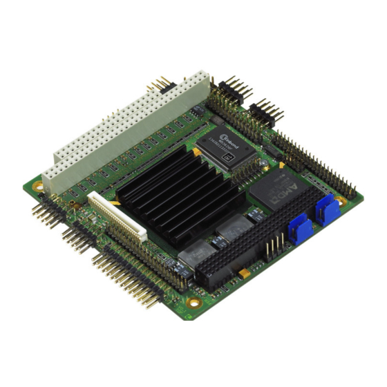
DIGITAL-LOGIC AG MSM800 SEV Manual V1.0A ESCRIPTION OF THE CONNECTORS Flat cable • 44pin IDE is: IDT Terminal for Dual Row (2.00mm grid) and 1.00mm flat cable • All others are: IDT Terminal for Dual Row 0.1" (2.54mm grid) and 1.27mm flat cable... - Page 42 DIGITAL-LOGIC AG MSM800 SEV Manual V1.0A Top Side of the MSM800SEV V1.2...
- Page 43 DIGITAL-LOGIC AG MSM800 SEV Manual V1.0A Bottom Side of the MSM800SEV V1.2...
- Page 44 DIGITAL-LOGIC AG MSM800 SEV Manual V1.0A Serial Port COM1 Header onboard: D-SUB connector:: Signal Pin 1 Pin 1 = DCD Pin 2 Pin 6 = DSR Pin 3 Pin 2 = RxD Pin 4 Pin 7 = RTS Pin 5...
- Page 45 DIGITAL-LOGIC AG MSM800 SEV Manual V1.0A IDE interface Signal Signal Pin 1 = Reset (active low) Pin 2 = GND Pin 3 = D7 Pin 4 = D8 Pin 5 = D6 Pin 6 = D9 Pin 7 = D5...
- Page 46 DIGITAL-LOGIC AG MSM800 SEV Manual V1.0A Power supply Signal Signal Pin 1 = GND Pin 2 = VCCSUS +5Volt Input Supply Pin 3 = nc Pin 4 = (+12V input) Pin 5 = nc Pin 6 = PWR_BTN# Pin 7...
- Page 47 DIGITAL-LOGIC AG MSM800 SEV Manual V1.0A Keyboard PS/2/-Mouse Utility connector Attention: The speaker must be connected to VCC, to have a low inactive current in the speaker ! Signal Signal Pin 1 = Speaker Out Pin 2 = Ground (for Speaker)
- Page 48 DIGITAL-LOGIC AG MSM800 SEV Manual V1.0A LCD TFT Interface (flatpanel signals) Signal TFT 18 Bit TFT 24 Bit FPM (out) CRT-Vert.Synch VSYNC VSYNC Enable BKL (TTL out) CRT:Horiz.Synch HSYNC HSYNC VCC 3.3V Ground Shift Clock Enable VDD (TTL out) ENLVDD...
- Page 49 DIGITAL-LOGIC AG MSM800 SEV Manual V1.0A VGA monitor (CRT-Signals) J2 Header 15 pins HiDensity DSUB 10 Pin -M Signal Signal Pin 2 VGA red Pin 1 Pin 4 VGA green Pin 2 Green Pin 6 VGA blue Pin 3 Blue...
- Page 50 DIGITAL-LOGIC AG MSM800 SEV Manual V1.0A 10/100 BASE-T interface connector J17 Pin * Signal Signal Pin 1 = TX- Pin 2 = TX+ Pin 3 = RX- Pin 4 = RX+ Pin 5 = Activity LED Pin 6 = BAT input 3.0-3.6V...
- Page 51 DIGITAL-LOGIC AG MSM800 SEV Manual V1.0A PC/104 BUS interface Ground Ground IOCHCK Ground SBHE MEMCS16 RESET LA23 IOCS16 LA22 IRQ10 IRQ9 LA21 IRQ11 LA20 IRQ12 DRQ2 LA19 IRQ15 (-12V) LA18 IRQ14 LA17 DACK0 +12V MEMR DRQ0 IOCHRDY Ground NC MEMW...
- Page 52 DIGITAL-LOGIC AG MSM800 SEV Manual V1.0A PC/104+ BUS interface GND/5.0V KEY2 Reserved AD00 VI/O AD02 AD01 AD05 AD04 AD03 C/BE0* AD07 AD06 AD09 AD08 AD11 VI/O AD10 M66EN AD14 AD13 AD12 +3.3V C/BE1* AD15 +3.3V SERR* SB0* PERR* +3.3V SDONE STOP* +3.3V...
-
Page 53: Jumper Locations On The Board
DIGITAL-LOGIC AG MSM800 SEV Manual V1.0A UMPER LOCATIONS ON THE BOARD Jumper locations on the board The figure shows the location of all jumper blocks on the MSM800SEV board. The numbers shown in this figure are silk screened on the board so that the pins can easily be located. This chapter refers to the indi- vidual pin for these jumpers. -
Page 54: Cable Interface
DIGITAL-LOGIC AG MSM800 SEV Manual V1.0A ABLE INTERFACE The harddisk cable 44pin IDT Terminal for Dual Row (2.00 mm grid) and 1.00 mm flat cable. 44 pins = 40 pins signal and 4 pins power. Max. length for the IDE cable is 30 cm. -
Page 55: The Com 1/2 Serial Interface Cable
DIGITAL-LOGIC AG MSM800 SEV Manual V1.0A The COM 1/2 serial interface cable DT terminal for dual row 0.1" (2.54 mm grid) and 1.27 mm flat cable. Line of pin 1 COM1 9pin D-Sub male COM1/2 ATTENTION: Do not short-circuit these signal lines. -
Page 56: The Printer Interface Cable
The printer interface cable IDT terminal for dual row 0.1" (2.54mm grid) and 1.27 mm flat cable Parallelport Cable LPT1 ATTENTION: Maximum length of this cable is 6 meters. Prevent short-circuits. Never apply power to these signals, the MICROSPACE MSM800SEV will be destroyed. -
Page 57: The Micro Floppy Interface Cable
DIGITAL-LOGIC AG MSM800 SEV Manual V1.0A The Micro Floppy interface cable... -
Page 58: Operating Systems Compatibility
DIGITAL-LOGIC AG MSM800 SEV Manual V1.0A PERATING YSTEMS OMPATIBILITY The CPU PENTIUM is fully compatible to other PC-standard CPUs. The Intel chipsets are also fully PC- compatible. No incompatibilities are known. Microsoft Windows This system is fully compatible with Windows 2000, Windows XP Professional Microsoft Windows CE 4.2 / 5.0... -
Page 59: Driver Installation
DIGITAL-LOGIC AG MSM800 SEV Manual V1.0A 10 D RIVER NSTALLATION 10.1 Windows 2000 & XP On the MICROSPACE Application CD you will find all tools and drivers you will need to work with the card. If you are not sure about the topicality of the software, please visit our homepage at http://www.digitallogic.com... - Page 60 DIGITAL-LOGIC AG MSM800 SEV Manual V1.0A...
- Page 61 DIGITAL-LOGIC AG MSM800 SEV Manual V1.0A...
-
Page 62: Audio / Multimedia
DIGITAL-LOGIC AG MSM800 SEV Manual V1.0A 10.1.2 Audio / Multimedia Enter the device manager and follow the description below:... -
Page 63: Vga
DIGITAL-LOGIC AG MSM800 SEV Manual V1.0A 10.1.3 Enter the device manager and follow the description below:... - Page 64 DIGITAL-LOGIC AG MSM800 SEV Manual V1.0A...
-
Page 65: Ethernet / Lan
DIGITAL-LOGIC AG MSM800 SEV Manual V1.0A 10.1.4 Ethernet / LAN Enter the device manager and follow the description below:... - Page 66 DIGITAL-LOGIC AG MSM800 SEV Manual V1.0A...
-
Page 67: Int15 Emulator Driver For W2K/Xp
DIGITAL-LOGIC AG MSM800 SEV Manual V1.0A 10.1.5 Int15 emulator driver for W2k/XP Location: \Tools\MPC4x_x-MPCF40_MPCV855\int15dl\ int15dl_install19.exe How to: Execute the file int15dl_install19.exe After installation of this driver you can use the tools: WinInt15.exe (Int15 function test tool) and T855.exe (Temperatur sensor (SMBUS) monitor) chapter 11.1... -
Page 68: Software
DIGITAL-LOGIC AG MSM800 SEV Manual V1.0A 11 S OFTWARE 11.1 Windows Int15 Tool Please find the tool and the driver under: x:\tools\int15dl on the product CD or in the download area of the support center. Note: Before you can use these tools, you have to install the Windows WDM driver first. -
Page 69: Special Peripherals, Configuration, Software
DIGITAL-LOGIC AG MSM800 SEV Manual V1.0A 12 S PECIAL ERIPHERALS ONFIGURATION OFTWARE 12.1 The Special Function Interface for MICROSPACE Computers SFI All functions are performed by starting the SW-interrupt 15hex with the following arguments: 12.1.1 INT 15h SFR Functions Function:... - Page 70 DIGITAL-LOGIC AG MSM800 SEV Manual V1.0A Function: READ SERIAL NUMBER Number: Description: Reads the serialnumber from the board into the serial EEPROM Input values: DLAG Int15 function Function request Serial Number (Binary, not ASCI) Outputs values: Function: WRITE PRODUCTION DATE & RESET DLAG-COUNTERS...
- Page 71 DIGITAL-LOGIC AG MSM800 SEV Manual V1.0A Function: READ INFO 2 FROM EEPROM Number: Description: Reads the information bytes out of the serial EEPROM Input values: DLAG Int15 function Function request Board Type BOARD TYPE ('M'=PC/104, 'E'=Euro, 'W'=MSWS, Output values: 'S'=Slot, 'C'=Custom, 'X'= smartCore or smartModule CPU Type bits 1…7 and board type bits 8…15 (CPU type:...
-
Page 72: Int15 Emulator Driver For Windows
Access under Windows 98, ME , 2000, XP can be provided over "Int15dl"-WDM driver, under Windows-NT "Int15dl"-NT driver. For the moment this driver support all Digital-Logic boards with PIIX4 and ICH4 chipsets (eg. MSM855, MSEBX855, MSMP5SEV, MSMP3SEV, MSEP800…). Please find the driver under: \products\***\TOOLS\int15dl on the product CD or in the download area of the support center. - Page 73 "Regs.ah = 0xEC;", but on the board with ICH4 chipset, please use "Regs.ax = 0x78EC;". bool Open_Int15dl(void) - the first function, which must be called to create a link between "Digital-Logic INT15 functions emulator" driver and user software. It returns “true”, if device was successfully opened, otherwise - “false”.
- Page 74 HKR, "Parameters", "tsaddr", 0x00010001, 0x9E - LM75 sensor address for ICH4 chipset: HKR, "Parameters", "chipID", 0x00010001, 0x5 HKR, "Parameters", "pmBase", 0x00010001, 0x1000 HKR, "Parameters", "smbBase", 0x00010001, 0x1880 HKR, "Parameters", "tsaddr", 0x00010001, 0x9C - ADM1023 sensor address For more information, please get in contact with the Digital-Logic support department.
-
Page 75: Starting Up The System
Connect a floppy: does the bezel LED light blink? Does the harddisk spindle motor start? Reset the CMOS-RAM C. If the error appears again Contact your nearest DIGITAL-LOGIC distributor for Technical Support. Or fill out the support request form (SRF) on the Internet: http://www.digitallogic.com / Support... -
Page 76: Post Codes
DIGITAL-LOGIC AG MSM800 SEV Manual V1.0A 13.2 POST CODES BIOS POST CODES Checkpoint Function Name Intermediate Function Description Codes Reset Vector XpressROM code execution start UserPrelnit User added code to be run first PreSiolnit First SIO access, Core SIO initialize, LPT can be mapped to 1/0 80h for embedded devices to provide POST code output. - Page 77 DIGITAL-LOGIC AG MSM800 SEV Manual V1.0A Checkpoint Function Name Intermediate Function Description Codes memRAMoptimize SDRAM optimization for CPU speed 013h cacheInit Autosize and initialize Cache Cache failed to size to 16 K113 (i.e., 013h failed) northBridgelnit Load Geode North Bridge PCI register space...
-
Page 78: Core Bios
DIGITAL-LOGIC AG MSM800 SEV Manual V1.0A 14 C BIOS 14.1 Setup Menu Screens and Navigation The XpressROMTM Setup Menu contains a number of features and options. It is recommend to evaluate the menu options prior to shipment of your platform to ensure the removal of options that could have a negative consequence if users change the items. - Page 79 DIGITAL-LOGIC AG MSM800 SEV Manual V1.0A Mother Board Device Configuration The Mother Board Device configuration contains the only sub menu system of the setup screens. The choices are Drive Configuration: Allows the configuration of the IDE drive I/O Configuration: Allows for the configuration of the serial ports on the CS5535/CS5536...
- Page 80 DIGITAL-LOGIC AG MSM800 SEV Manual V1.0A PRE2ACT: Pre to ACT period (tRP). Minimum number of SDROM clocks between PRE and ACT commands ACT2CMD: Delay time from ACT to Read/Write (tRCD). Minimum number of SDRAM clocks between ACT and Read/Write Commands ACT2ACT: ACT(0) to ACT(1) Period (tRRD).
- Page 81 DIGITAL-LOGIC AG MSM800 SEV Manual V1.0A Power Management The Power Management menu is for configuration of the BIOS’s power management with relation to the OS on the platform. BIOS PM at Boot: The BIOS PM allows setting of legacy power management mode prior to booting the sys- APM Available: Allows the system to configure if the APM interface is available.
-
Page 82: Motherboard
DIGITAL-LOGIC AG MSM800 SEV Manual V1.0A Boot Order The Boot Order menu allows the alteration of the devices checked for a bootable image. There are six slots for selecting the order. Use the arrow keys to select the order number and then press enter to cycle through the options. - Page 83 DIGITAL-LOGIC AG MSM800 SEV Manual V1.0A Flash Configuration: Allows the use of a flash device over the IDE. The options are Enable or Dis- able Chip Select 0- 3 Size: Allows the configuration of the flash chips to be disabled, 8K/16B, 16K/32B,...
- Page 84 DIGITAL-LOGIC AG MSM800 SEV Manual V1.0A LPC Card Configuration The LPC card configuration enables the configuration of each serial port and the parallel port on the LPC. To change the serial port configuration use the arrow keys ( ) to select the serial port and hit <enter> to change the state the choices are Disabled, 0x3F8 IRQ 4, 0x2F8 IRQ 3, 0x3E8 IRQ 4, 0x2E8 IRQ3 Parallel Port: Allows the selection of the parallel port address.
- Page 85 DIGITAL-LOGIC AG MSM800 SEV Manual V1.0A HSYNC Polarity: Selects the active polarity of the HSYNC signal to the panel. The options are Ac- tive Low or Active High VSYNC Polarity: Selects the active polarity of the VSYNC signal to the panel. The options are Ac- tive Low or Active High LP Active Period: Selects the active period of the LDE/MOD (LP) signal.
- Page 86 DIGITAL-LOGIC AG MSM800 SEV Manual V1.0A PCI Configuration The following menu system allows the configuration of the PCI interrupts. Select the PCI interrupt desired to change and hit <enter> to cycle through the IRQs. For the USB 2.0 the options are as follows:...
-
Page 87: Assemblings View
DIGITAL-LOGIC AG MSM800 SEV Manual V1.0A 15 A SSEMBLINGS VIEW 15.1 MSM800SEV 1.2... - Page 88 DIGITAL-LOGIC AG MSM800 SEV Manual V1.0A...
-
Page 89: Drawings Of Older Board Versions
DIGITAL-LOGIC AG MSM800 SEV Manual V1.0A 16 D RAWINGS OF OLDER BOARD VERSIONS 16.1 Version 1.0 / V1.1... - Page 90 DIGITAL-LOGIC AG MSM800 SEV Manual V1.0A...
-
Page 91: 17 Index
DIGITAL-LOGIC AG MSM800 SEV Manual V1.0A 17 INDEX 10/100 BASE-T interface I/O map IDE interface 10, 45 Incompatibilities Input Signals INT 15h SFR Functions Addressing PCI devices Int15 emulator driver for Windows 67, 68, 72 Application Notes Int15 Windows Software... - Page 92 DIGITAL-LOGIC AG MSM800 SEV Manual V1.0A printer interface cable Printerport Programming Int15dl Technical Support PS/2 Thermoscan Realtime OS ROM-BIOS Utility Connector Schematics 39, 63 serial interface cable VGA monitor Serial Ports 24, 44 Sound/Audio Port Speaker Watchdog Special Function Interface...
Need help?
Do you have a question about the MICROSPACE MSM800SEV and is the answer not in the manual?
Questions and answers